BBW - DBW 46 - VW-Bus-T4.de
BBW - DBW 46 - VW-Bus-T4.de
BBW - DBW 46 - VW-Bus-T4.de

Create successful ePaper yourself
Turn your PDF publications into a flip-book with our unique Google optimized e-Paper software.
<strong>BBW</strong> <strong>46</strong> / <strong>DBW</strong> <strong>46</strong><br />
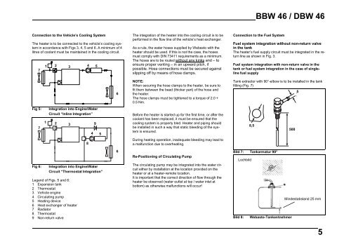
Connection to the Vehicle’s Cooling System<br />
The heater is to be connected to the vehicle’s cooling system<br />
in accordance with Figs 3, 4, 5 and 6. A minimum of 4<br />
litres of coolant must be maintained in the cooling circuit.<br />
7<br />
1 2 3 4 5<br />
6<br />
The integration of the heater into the cooling circuit is to be<br />
performed in the flow line of the vehicle’s heat exchanger.<br />
As a rule, the water hoses supplied by Webasto with the<br />
heater should be used. If this is not the case, the hoses<br />
must comply with DIN 73411 requirements as a minimum.<br />
The hoses are to be routed without any kinks and – to<br />
ensure proper venting – in an upward pitch, if<br />
possible. Hose connections must be secured against<br />
slipping off by means of hose clamps.<br />
NOTE:<br />
When securing the hose clamps to the heater, be sure to<br />
fit them between the bead (thicker part) of the hose and<br />
the heater.<br />
The hose clamps must be tightened to a torque of 2.0 +<br />
0.5 Nm.<br />
Connection to the Fuel System<br />
Fuel system integration without non-return valve<br />
in the tank<br />
The heater’s fuel supply circuit must be integrated in the return<br />
line as shown in Fig. 3.<br />
Fuel system integration with non-return valve in the<br />
tank or fuel system integration in the case of singleline<br />
fuel supply<br />
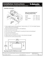
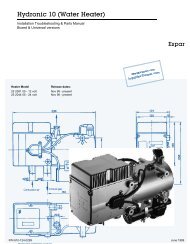
Tank extractor with 90°-elbow is to be installed in the tank<br />
fitting (Fig. 7)<br />
5<br />
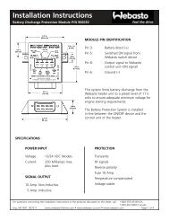
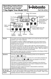
Fig 5:<br />
7<br />
1<br />
Integration into Engine/Water<br />
Circuit “Inline Integration”<br />
2<br />
3<br />
8<br />
4<br />
9<br />
5<br />
Before the heater is started up for the first time, or after the<br />
coolant has been replaced, it must be ensured that the<br />
cooling system is properly bled. Heater and piping should<br />
be installed in such a way that static bleeding of the system<br />
is ensured.<br />
During heating operation, inadequate bleeding may lead to<br />
a malfunction due to overheating.<br />
8,5<br />
500<br />
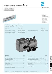
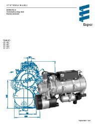
Fig 6:<br />
Integration into Engine/Water<br />
Circuit “Thermostat Integration”<br />
Legend of Figs. 5 and 6:<br />
1 Expansion tank<br />
2 Thermostat<br />
3 Vehicle engine<br />
4 Circulating pump<br />
5 Heating device<br />
6 Heat exchanger of heater<br />
7 Radiator<br />
8 Thermostat<br />
9 Non-return valve<br />
6<br />
Re-Positioning of Circulating Pump<br />
The circulating pump may be integrated into the water circuit<br />
either by installation at the location provided on the<br />
heater or at a heater-remote location.<br />
It is important that the correct direction of flow through the<br />
heater be observed (water outlet at top / water inlet at<br />
bottom) as otherwise malfunctions will occur!<br />
Bild 7: Tankarmatur 90°<br />
Lochbild<br />
Mindestabstand 25 mm<br />
Bild 8: Webasto-Tankentnehmer<br />
5