HYDRONIC 10.pdf - VW-Bus-T4.de
HYDRONIC 10.pdf - VW-Bus-T4.de
HYDRONIC 10.pdf - VW-Bus-T4.de

Create successful ePaper yourself
Turn your PDF publications into a flip-book with our unique Google optimized e-Paper software.
Water heater 10<br />
Technical Description<br />
Installation Instructions<br />
Operating Instructions<br />
Eberspächer<br />
Customer<br />
documentation<br />
J. Eberspächer<br />
GmbH & Co.<br />
Eberspächerstr. 24<br />
D - 73730 Esslingen<br />
Telefon (zentral)<br />
(0711) 939 - 00<br />
Telefax<br />
(0711) 939 - 0500<br />
http://www.<br />
eberspaecher.de<br />
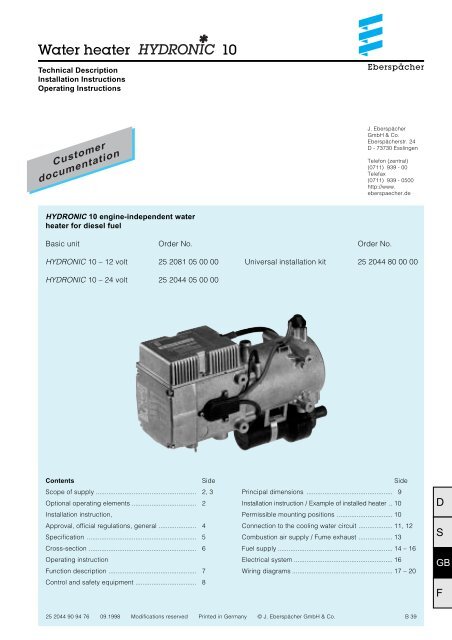
<strong>HYDRONIC</strong> 10 engine-independent water<br />
heater for diesel fuel<br />
Basic unit<br />
Order No.<br />
Order No.<br />
<strong>HYDRONIC</strong> 10 – 12 volt 25 2081 05 00 00<br />
Universal installation kit 25 2044 80 00 00<br />
<strong>HYDRONIC</strong> 10 – 24 volt 25 2044 05 00 00<br />
Contents Side<br />
Scope of supply ........................................................ 2, 3<br />
Optional operating elements .................................... 2<br />
Installation instruction,<br />
Approval, official regulations, general ..................... 4<br />
Specification ............................................................. 5<br />
Cross-section ............................................................ 6<br />
Operating instruction<br />
Function description ................................................. 7<br />
Control and safety equipment .................................. 8<br />
Side<br />
Principal dimensions ................................................ 9<br />
Installation instruction / Example of installed heater .. 10<br />
Permissible mounting positions ............................... 10<br />
Connection to the cooling water circuit ................... 11, 12<br />
Combustion air supply / Fume exhaust ................... 13<br />
Fuel supply ................................................................ 14 – 16<br />
Electrical system ....................................................... 16<br />
Wiring diagrams ........................................................ 17 – 20<br />
D<br />
S<br />
GB<br />
F<br />
25 2044 90 94 76 09.1998 Modifications reserved Printed in Germany 1 © J. Eberspächer GmbH & Co. B 39
Scope of supply<br />
Optional operating elements<br />
Quantity / Name<br />
Order No.<br />
Quantity / Name<br />
Order No.<br />
Basic unit with standard equipment<br />
<strong>HYDRONIC</strong> 10 – 12 volt 25 2081 05 00 00<br />
<strong>HYDRONIC</strong> 10 – 24 volt 25 2044 05 00 00<br />
The standard equipment includes:<br />
1 Standard unit with control unit<br />
and water pump (not available by itself)<br />
<strong>HYDRONIC</strong> 10 – 12 volt 25 2081 01 00 00<br />
<strong>HYDRONIC</strong> 10 – 24 volt 25 2044 01 00 00<br />
1 Fuel dosing pump<br />
with built-in fuel filter<br />
1 Relay<br />
also to be ordered:<br />
1 Universal installation kit 25 2044 80 00 00<br />
1 ”mini” timer – 12 / 24 volt 22 1000 31 31 00<br />
The ”mini” timer can be combined<br />
with radio-wave remote control TP 41.<br />
1 Radio-wave remote control 22 1000 31 35 00<br />
TP 41 – 12 / 24 volt<br />
Radio-wave remote control TP 41 can be used<br />
either separately or in combination with the<br />
”mini” timer (Cat. No. 22 1000 31 31 00).<br />
1 Modular timer – 12 / 24 volt 22 1000 30 34 00<br />
The modular timer can be combined<br />
with radio-wave remote control TP 4.<br />
Special accessory<br />
1 Cable harness for TRS operation<br />
(GGVS or ADR) 25 1816 80 06 00<br />
1 Return valve 254 00 074<br />
1 Thermostat 330 00 124<br />
1 Conversion kit for external<br />
installation of the water pump 22 1000 10 01 00<br />
See Additional Parts Catalog for further accessories.<br />
1 Set of mounting parts for 25 1482 70 01 00<br />
modular timer (only required<br />
when installing with trim)<br />
1 Radio-wave remote control 22 1000 30 63 00<br />
TP 4 – 12 / 24 volt<br />
Radio-wave remote control TP 4 can only be used<br />
in combination with the modular timer.<br />
D<br />
S<br />
GB<br />
F<br />
2
Scope of supply<br />
D<br />
S<br />
Water heater <strong>HYDRONIC</strong> 10<br />
Fuel dosing pump<br />
Relay<br />
Parts without a Fig. No. are contained<br />
in the universal installation kit.<br />
GB<br />
F<br />
3
D<br />
S<br />
GB<br />
F<br />
Installation instruction<br />
Heaters are used in conjunction with the vehicle heating<br />
system to preheat truck engines, warm cabs and defrost<br />
windows .<br />
They are connected up to the cooling water circuit,<br />
the electrical system and the fuel system of the vehicle.<br />
Approval,<br />
official regulations,<br />
general<br />
1 . For vehicles registered in West Germany (subject to the<br />
road traffic regulations StVZO), the heaters are approved<br />
by the Federal Motor Vehicle Office and receive an official<br />
test symbol indicated on the name plate.<br />
The year of first operation is a requirement of German<br />
approval not representing a model number.<br />
2. If the heater is installed in special-purpose vehicles<br />
(e.g. vehicles transporting dangerous cargoes),<br />
the regulations applicable to such vehicles must be<br />
observed.<br />
3. The heater must not be operated in closed rooms,<br />
e.g. garages.<br />
The heater must always be switched off when the petrol<br />
tank is to be filled.<br />
4. The heaters must be installed by a workshop approved by<br />
the manufacturer and in compliance with the installation<br />
instructions.<br />
5. The heaters may only be used for the purpose specified<br />
by the manufacturer and in compliance with the operating<br />
instructions supplied with every heater.<br />
Operating the heater is not permitted where inflammable<br />
vapours or dust can build up (e.g. near fuel, coal or<br />
sawdust stores, grain silos etc.).<br />
6. Differences from the installation instructions, particularly<br />
with regard to the water supply connection, wiring (wiring<br />
diagrams, fuel supply, combustion air and exhaust ducts,<br />
and use of operating and control elements not supplied<br />
by the manufacturer, are only permissible with the written<br />
approval of the manufacturer.<br />
Since water heaters are incorporated into the cooling<br />
system of the vehicle engine, they form an integral part<br />
of the cooling system.<br />
The following points must therefore be borne in mind:<br />
6.1 The heater must always be mounted below the<br />
cooling water level of the radiator or vehicle heat<br />
exchanger in such a way that it operates in the flow<br />
direction of the engine circuit.<br />
6.2 The entire cooling system including the heater must<br />
be bled to free it of bubbles following installation and<br />
in accordance with the engine manufacturer's<br />
specifications. All water connections (clips) must be<br />
tightened sufficiently to prevent all leaks and then<br />
retightened after 2 hours of operation or 100 km<br />
driving.<br />
6.3 All water ducts must be protected against chafing<br />
and excessive temperatures (radiated heat from<br />
exhaust pipes).<br />
6.4 Following any work on the cooling water system<br />
(repairs, cooling water change), the system must be<br />
bled as set forth in 6.2.<br />
6.5 The coolant should contain at least 10 % antifreeze<br />
all year round as corrosion protection.<br />
In cold weather the coolant must contain antifreeze<br />
in sufficient quantity. Operating the heater with frozen<br />
coolant is not permitted.<br />
If the above instructions are not complied with, the<br />
manufacturer's warranty for the entire heater system is<br />
null and void, and possibly the general operating permit<br />
for the vehicle.<br />
7. Every combustion process generates exhaust gas, which<br />
has toxic constituents. Because of this and the high<br />
temperatures generated, the exhaust duct must comply<br />
without fail with the installation instructions. Failure to<br />
comply with the instructions or operation of the heater<br />
in closed rooms (garages) harbours the risk of poisoning.<br />
8. When the heater or the heating system is damaged,<br />
an authorized workshop must be called in to repair<br />
the damage in an expert manner and using genuine<br />
spare parts.<br />
Makeshift repairs (on one's own initiative) or the use of<br />
non-genuine spare parts are dangerous, and therefore<br />
not permitted. When carried out in cars, they invalidate<br />
the general design approval of the heater and<br />
consequently the general permit of the vehicle.<br />
9. The warranty conditions are set forth in the heater booklet<br />
given to you by the after-sales service workshop when the<br />
heater is installed.<br />
Only our warranty conditions shall apply.<br />
Safety Instructions<br />
A trial run of the heater should be performed before the<br />
heating period commences. The heater must be switched off<br />
if dense smoke is persistently formed and closed down by<br />
removing the safety device. The heater should only be<br />
operated again after it has been inspected by trained<br />
Eberspächer servicing personnel. Observance of these<br />
operating instructions is a precondition for liability claims.<br />
Non-observance of the technical description, mounting and<br />
operating instructions, as well as unprofessional repairs or<br />
the use of non-original spare parts, exclude any liability on<br />
the part of Eberspächer.<br />
4
Specification<br />
Heater <strong>HYDRONIC</strong> 10<br />
Heating medium<br />
Water, cooling water<br />
Regulation of heating capacity Power Large Medium Small<br />
Heating capacity (watts) 9500 7500 3200 1500<br />
Fuel consumption (l/h) 1.2 0.9 0.4 0.18<br />
Electric power consumption in operation – 12 volt 125 80 48 36<br />
(watts)<br />
in operation – 24 volt 115 73 45 33<br />
on start-up – 12 volt 139<br />
on start-up – 24 volt 137<br />
in the regulation break ”Off” 28<br />
Rated voltage<br />
Operating range<br />
Min. voltage<br />
An undervoltage protection device incorporated<br />
in the control unit cuts out at approx. 10.5 V or 20 V<br />
Max. voltage<br />
An overvoltage protection device incorporated<br />
in the control unit cuts out at approx. 15 V or 30 V<br />
Max. allowable working pressure<br />
Water flow rate of water pump against 0.14 bar<br />
Min. water flow rate of heater<br />
Fuel<br />
see also ”Fuel at low temperatures”<br />
12 V or 24 V<br />
10.5 V or 20 V<br />
15 V or 30 V<br />
up to 2.0 bar overpressure<br />
1400 l/h<br />
500 l/h<br />
diesel fuel – commercial grade<br />
Max. allowable ambient temperature Operation –40 °C to +80 °C<br />
Storage –40 °C to +85 °C<br />
Radio interference<br />
suppression level<br />
Weight incl. control unit and water pump,<br />
without dosing pump<br />
Technical data ± 10 %<br />
3 for UKW<br />
4 for KW<br />
5 for MW/LW<br />
approx. 6.5 kg<br />
D<br />
S<br />
GB<br />
F<br />
5
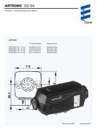
Cross-section<br />
D<br />
S<br />
GB<br />
F<br />
1 Combustion motor<br />
2 Flame sensor<br />
3 Combustion chamber<br />
4 Control unit<br />
5 Heater plug<br />
6 Temperature sensor<br />
7 Flame tube<br />
8 Heat exchanger<br />
9 Overheating switch<br />
10 Water pump<br />
11 Exhaust silencer<br />
12 Combustion air silencer<br />
13 Fuel feeder pump<br />
14 Fuel branch piece<br />
15 Cable tree<br />
16 Fuse bracket<br />
17 Relay for switching on the vehicle’s fan<br />
18 Automatic switch<br />
WE = Water inlet<br />
WA = Water outlet<br />
V = Combustion air<br />
B = Fuel<br />
A = Fumes<br />
6
Operating instruction<br />
Function description<br />
Switching on<br />
When the heater is turned on, the control lamp in the<br />
switch or in the automatic heater switch lights up.<br />
The combustion-air fan and the water pump start up<br />
and the heater plug's preheating phase commences.<br />
Start-up<br />
After the preheating phase of approx. 60 seconds,<br />
the feeder pump starts up and fuel is supplied to the<br />
combustion chamber. Ignition follows. Then the<br />
combustion-air fan speeds up infinitely along with<br />
the feeder pump's impulse frequency to the<br />
"POWER" stage with 9500 watts to achieve the<br />
required temperature in the combustion chamber.<br />
The time-controlled heater plug is switched off.<br />
A second start commences when the flame sensor<br />
does not recognize a flame. The heater with afterrunning<br />
switches to fault when a flame is not<br />
recognized during the second phase.<br />
Control in heating mode<br />
When the heater is first started up after switch-on,<br />
or during normal operation, it works in the "POWER"<br />
setting 9500 W until<br />
• either the water temperature exceeds the switchover<br />
threshold "POWER" / "LARGE" (e.g. 72 °C),<br />
• or<br />
the max. operating time of two hours for this<br />
stage is exceeded.<br />
Depending on the amount of heat extracted, the<br />
heater switches to one of the "POWER – LARGE –<br />
MEDIUM – SMALL – OFF" stages. If the cooling<br />
water temperature reaches 55 °C temperature<br />
reaches a maximum of 85 °C in the individual control<br />
stages.<br />
• The heater switches to "POWER" mode when the<br />
heat extracted equals or exceeds 9500 watts.<br />
• The heater will switch between "POWER and<br />
LARGE" when heat extraction is between 9500<br />
and 7500 watts.<br />
• The heater will switch between "LARGE and<br />
MEDIUM" when heat extraction is between 7500<br />
and 3200 watts.<br />
• The heater will switch between "MEDIUM and<br />
SMALL" when heat extraction is between 3200<br />
and 1500 watts.<br />
• The heater operates in the "SMALL" stage when<br />
heat extraction is 1500 watts or less.<br />
The heater will switch from "SMALL" into the<br />
control break when heat extraction in the "SMALL"<br />
stage is so low that the cooling water temperature<br />
reaches 85 °C. It will follow the after-running of<br />
210 seconds. The water pump continues until the<br />
heater is restarted.<br />
The heater starts in "MEDIUM" when the cooling<br />
water has cooled down to 70 °C (as an example).<br />
Attention!<br />
Set the vehicle's heater lever to "WARM" (maximum<br />
setting) and the fan to "slow" (low power consumption)<br />
before activating or preprogramming heater<br />
operation.<br />
The operating instructions for the timers and<br />
switches are supplied with the operating elements.<br />
In the case of vehicles equipped with an automatic<br />
heater, set the heating lever to MAX and the flap to<br />
the desired OPEN position before switching off the<br />
ignition.<br />
Operating elements (see Page 2).<br />
If switches other than those normally used in the<br />
automotive industry are to be used, make sure that<br />
their current carrying capacities amount to at least<br />
1 amperes.<br />
Version TRS 003<br />
The stipulations of TRS 003 must be fulfilled when<br />
the heaters are to be installed to heat driver cabs in<br />
tanker vehicles transporting hazardous materials in<br />
areas where the German highway code (StVZO)<br />
applies. See circuit diagram.<br />
The heater must only be operated in TRS mode if a<br />
special cable harness (supplementary part) is<br />
installed, cat. no. 25 1816 80 06 00.<br />
Heating operation at high altitudes<br />
• up to 1500 m: unrestricted heating operation,<br />
• above 1500 m: Heating operation is possible<br />
during a short stay (e.g. crossing<br />
a mountain pass, taking a rest).<br />
If a longer stay is planned (e.g. winter camping), the<br />
fuel has to be adapted to the altitude. In this case,<br />
please consult the heater manufacturer for advice.<br />
D<br />
S<br />
GB<br />
F<br />
7
Control and safety equipment<br />
The flame is monitored by the flame sensor, the max.<br />
permissible temperature by the overheating sensor.<br />
Both affect the control unit which switches the<br />
heater off when faults occur.<br />
• The start will be repeated if the heater doesn't<br />
ignite within 105 seconds after fuel has started<br />
to be supplied.<br />
The heater will be switched off if it doesn't ignite<br />
within 75 seconds after fuel has started to be<br />
supplied with the second start.<br />
After a certain number of unsuccessful starting<br />
attempts, a fault cutout is triggered.*<br />
• A new start will be triggered if the flame<br />
extinguishes itself during operation. The heater<br />
will be switched off if it does not ignite within<br />
105 seconds after fuel has started to be supplied.<br />
Switch the heater on and off again to cancel<br />
deactivation due to faults.<br />
• The overheating sensor is triggered by overheating,**<br />
which will result in the fuel supply being<br />
interrupted. The heater will then be switched off.<br />
Once the cause of overheating has been<br />
remedied, the heater can be restarted by<br />
switching on and off again***.<br />
After a certain number of cutouts caused by<br />
overheating have occurred, a fault cutout is<br />
triggered.*<br />
• If the voltage drops below the lower limit or rises<br />
above the upper limit, a fault cutout is triggered.<br />
You can repair the following faults yourself<br />
If the heater does not start after being switched on:<br />
1. Check the 3 fuses:<br />
15 A / 24 V, 20 A / 12 V for the heater,<br />
5 A for activation,<br />
25 A for the vehicle fan (when this fuse has<br />
blown, the heater will start, but no hot air will be<br />
delivered)<br />
in the fuse box between the battery and heater.<br />
2. Check the heater plug and change if necessary.<br />
3. Switch the heater off. and back on again.<br />
Please note:<br />
• To provide protection against corrosion, the<br />
cooling agent should contain at least 10 %<br />
antifreeze the whole year round.<br />
• When carrying out electric welding on the vehicle,<br />
the plus pole must be disconnected from the<br />
battery and connected to ground to protect<br />
the control unit.<br />
• Switch on the heater for a short time once a<br />
month during periods in which it is not used (for<br />
approx. 10 seconds). This will prevent the water<br />
pump and combustion engine from seizing.<br />
• The heater will not start if the heater plug is faulty<br />
and the electric line to the feeder pump has been<br />
interrupted.<br />
• The speed-regulated combustion motor is<br />
permanently monitored. In the event of a fault, if it<br />
doesn't start, is blocked or when its speed falls<br />
below 40 % of the desired revolutions, the heater<br />
will switch to fault after a delay of 60 seconds.<br />
D<br />
S<br />
GB<br />
F<br />
* Connection of diagnosis unit<br />
(order no. 22 1512 89 00 00) instead of timer<br />
(3.2.5 in circuit diagram) can read off possible<br />
mistakes, or cancel the interlocking.<br />
For operation and fault list, operating instructions<br />
for diagnosis unit.<br />
** (no water, poorly ventilated cooling water<br />
circulation)<br />
***(that is if the unit has cooled sufficiently)<br />
8
Principal dimensions<br />
Water<br />
Combustion air<br />
Fumes<br />
Water<br />
Fuel<br />
Installing the heater<br />
Factory plate<br />
The heater is installed in the engine compartment,<br />
as low down as possible so that the heat exchanger<br />
and water pump can bleed themselves. Note which<br />
installation positions are permissible.<br />
The factory plate must be clearly visible with the<br />
heater installed. If necessary, a second plate<br />
(duplicate) may be affixed, with the same information<br />
as the original, to a place on the heater clearly<br />
visible after installation, or to a cover placed in front<br />
of the heater. A second plate is unnecessary if the<br />
original is visible after removal of a cover without the<br />
aid of tools.<br />
The factory plate is fitted to the basic heater.<br />
J. EBERSPÄCHER ESSLINGEN<br />
MADE IN GERMANY<br />
Heater type <strong>HYDRONIC</strong> 10<br />
Model<br />
D 10 W<br />
Factory no.<br />
Test symbol<br />
S<br />
Fuel<br />
Diesel<br />
Electrical values<br />
Heat flux 9500 W<br />
Operating<br />
max. 2.0 bars<br />
overpressure<br />
Do not install in<br />
passenger area<br />
BARCODE<br />
SP . . . AD . . .<br />
Year first commissioned<br />
®<br />
D<br />
S<br />
GB<br />
F<br />
9
Installation instruction / Example of installed heater<br />
Water heater in a transport vehicle<br />
Installation position<br />
If the vehicle is a transport vehicle,<br />
the water heater should be installed<br />
in the engine compartment,<br />
preferably below the level of the<br />
cab.<br />
6<br />
5<br />
4<br />
3 2<br />
1<br />
Water heater<br />
Running the exhaust<br />
Silencer<br />
Water outlet from heat exchanger<br />
Water inlet to heat exchanger<br />
Water outlet from engine<br />
Permissible mounting positions<br />
The water heater should be installed<br />
in the normal position shown in the<br />
diagram. The maximum permitted<br />
variation on this position is also<br />
shown. If any other mounting<br />
position is required, consult the<br />
manufacturer.<br />
D<br />
S<br />
GB<br />
F<br />
10
Connection to the cooling water circuit<br />
The pressure in the cooling water circuit must be<br />
limited by a pressure relief valve (e.g. radiator filler<br />
cap) to a maximum of 2 bars gauge pressure.<br />
There are four possibilities to do so:<br />
1. Using a thermostat in the supply line<br />
to the heater.<br />
Initially, the heat from the additional heater is<br />
supplied only to the driver’s cab up to a cooling<br />
water temperature of about 70 °C = small circuit,<br />
rapid heating.<br />
If the cooling water temperature rises further, the<br />
thermostat changes gradually (changeover<br />
completed at 75 °C) to the large circuit = additional<br />
engine preheating.<br />
Important!<br />
When operating with an additional heater, the<br />
heating valve must always be wide open.<br />
Recommendation:<br />
Use a switch with an N / C limit position contact for<br />
all heating circuits.<br />
Very important:<br />
Make the connections 1, 2 and 3 as shown in the<br />
sketch.<br />
Expansion Tank<br />
Flow only possible when<br />
engine is running<br />
Heater valve<br />
Thermostat, Ø 20 mm<br />
Order No. 330 00 124<br />
Radiator<br />
Radiator<br />
thermostat<br />
Water<br />
pump<br />
Engine<br />
t>75 °C<br />
Thermostat<br />
t75 °C<br />
Thermostat<br />
t
3. Heater in coolant line between engine and heat<br />
exchanger of vehicle, with non-return valve<br />
installed parallel. No thermostat.<br />
Advantage:<br />
Easy assembly.<br />
Disadvantage:<br />
Continuous flow through engine. Low cab heating<br />
efficiency in the case of large engines. For that<br />
reason only recommended for small engines.<br />
Expansion Tank<br />
Flow only possible when<br />
engine is running<br />
Heater valve<br />
Radiator<br />
Radiator<br />
thermostat<br />
Engine<br />
Heater with<br />
water pump<br />
Vehicle heater<br />
with blower<br />
Water<br />
pump<br />
4. Instead of the thermostat in Example 1, an<br />
electrically operated changeover valve can be<br />
used for optional switching to small circuit<br />
(cab heating only) or large circuit (cab heating<br />
plus engine preheating).<br />
Advantage:<br />
Selection of heating circuit regardless of the<br />
temperature.<br />
Disadvantage:<br />
No automatic regulation possible, unlike in<br />
thermostat operation (1. and 2.).<br />
Recommendation: An additional non-return valve<br />
prevents any loss in the efficiency of engine preheating<br />
when the additional heater is switched off.<br />
Expansion Tank<br />
Heater valve<br />
D<br />
S<br />
Radiator<br />
Radiator<br />
thermostat<br />
Water<br />
pump<br />
Engine<br />
Heater with<br />
water pump<br />
Electrically operated changeover valve<br />
Vehicle heater<br />
with blower<br />
Flow:<br />
a = live<br />
b = no voltage<br />
GB<br />
F<br />
12
Combustion air supply / Fume exhaust<br />
<br />
<br />
<br />
<br />
<br />
<br />
Combustion air supply<br />
A silencer is fitted to the heater. The combustion air<br />
intake tube can also be extended by up to 2 m<br />
using a flexible tube. The inner diameter should be<br />
25 mm. Avoid sharp bends.<br />
The combustion air has to be taken from the outside<br />
(not from the occupant cell or the boot).<br />
Arrange the combustion air inlet so that exhaust gas<br />
cannot be directly drawn in again.<br />
Do not install the combustion-air line so that its inlet<br />
opening faces the oncoming wind; position it in such<br />
a way that it cannot be blocked by snow or dirt and<br />
that water can drain from it.<br />
Attach the end sleeve. This will guarantee that a ball<br />
with a diameter of 16 mm cannot be inserted.<br />
(Requirement in the "Technical Requirements for<br />
Heaters".)<br />
Fume exhaust<br />
A flexible fume hose (inner diameter 30 mm,<br />
1300 mm long) is included. It must be cut at<br />
a suitable place so that the fume silencer can be<br />
connected between it (see Fig. on Page 3).<br />
The exhaust tubes can be shortened or extended up<br />
to a maximum of 2 m if necessary.<br />
Exhaust tubes may not protrude beyond the<br />
vehicle's sides. Either fit the exhaust lines so that<br />
they are inclined downwards slightly or drill<br />
drainage holes of around 5 mm diameter at the<br />
lowest points so that condensation can run off.<br />
The exhaust outlet and the combustion air inlet must<br />
be so arranged that exhaust cannot be sucked in<br />
again directly.<br />
The exhaust outlet must be on the outside. Exhaust<br />
lines must be laid in such a way that neither the<br />
penetration of exhaust into the vehicle interior nor<br />
the intake of exhaust through the vehicle blower<br />
need be expected 1) , and that the operation of<br />
essential vehicle parts is not affected (ensure<br />
adequate clearance). Place the outlet opening of the<br />
exhaust line in such a way that it cannot be clogged<br />
by dirt and snow and that any water which does<br />
enter can run off. Do not install facing the slipstream.<br />
Attach the end sleeve. This will guarantee that a ball<br />
with a diameter of 16 mm cannot be inserted.<br />
(Requirement in the "Technical Requirements for<br />
Heaters".)<br />
1)<br />
This requirement is deemed met when the outlet<br />
of the exhaust pipe points upwards or to the side,<br />
or – when the exhaust is run under the vehicle<br />
floor – is positioned close to the side or rear edge<br />
of the cab or vehicle.<br />
Combustion air connection dia. 25 mm<br />
Combustion air silencer<br />
Exhaust pipe dia. 30 mm<br />
Exhaust silencer<br />
Intake aperture – protect from penetration<br />
by the airstream, snow, dirt and water<br />
D<br />
S<br />
GB<br />
F<br />
13
Fuel supply<br />
Requirements:<br />
The fuel line running to the engine must be tightly<br />
sealed to ensure that the fuel column does not break<br />
off while the engine is at rest.<br />
The supply pressure in the fuel line must not exceed<br />
0.3 bar in all operation conditions.<br />
Important!<br />
Be sure to comply with the following instructions in<br />
order to avoid damaging the heater and / or engine.<br />
Before using the water heater, prime the fuel pipes<br />
by starting the vehicle engine.<br />
1. Fuel is preferably tapped from the vehicle fuel<br />
tank or from a separate fuel tank with separate<br />
riser pipe (tank connection).<br />
Fuel connection<br />
on heater<br />
2. If difficulties arise in installing the rising tank<br />
connection, the supply line can be tapped.<br />
To engine<br />
mechanical fuel<br />
pump or<br />
injection pump<br />
Fuel connection<br />
on heater<br />
D<br />
S<br />
GB<br />
F<br />
Fuel tank (vehicle tank or separate tank)<br />
Fuel branch<br />
Fuel hose, internal dia. 5 mm<br />
Fuel pre-filter – only necessary when contaminated fuel is used<br />
Fuel metering pump (15° to vertically upwards)<br />
Fuel hose, internal dia. 3.5 mm<br />
Fuel pipe, plastic, internal dia. 2 mm<br />
Riser pipe (tank connection), internal dia. 4 mm<br />
Fuel pipe, internal dia. 4 mm<br />
14<br />
Permitted line lengths<br />
Suction side<br />
a = max. 2 m<br />
b = max. 50 mm<br />
c = max. 300 mm<br />
Discharge side<br />
d = max. 6 m<br />
at least 1.5 m<br />
(should shorter fuel lines be<br />
necessary please contact the<br />
manufacturer in advance)
Mounting position for metering pump<br />
Permitted height for induction and discharge<br />
sides of metering pump<br />
a<br />
b<br />
2<br />
3<br />
max.90°<br />
Metering pump<br />
Max. fuel level<br />
Min. fuel level<br />
Connection to heater<br />
1<br />
min. 15°<br />
c<br />
4<br />
Mounting position for delivery pump<br />
Install metering pump with discharge side at an<br />
angle of min. 15° to 90° sloping upwards in vehicle.<br />
Fuel line, metering pump to heater, should not have<br />
a slope if at all possible.<br />
Permitted height of induction and discharge sides<br />
Discharge side height from vehicle tank to metering<br />
pump:<br />
a = max. 1000 mm<br />
Suction head: with tank at zero pressure:<br />
b = max. 750 mm<br />
Note:<br />
Check whether tank ventilation is working properly<br />
Height of induction side if fuel drawn from a vehicle<br />
tank in which a partial vacuum occurs on withdrawal:<br />
b = max. 400 mm<br />
Note: Valve 0.03 bars in tank cap<br />
Pressure head, metering pump to heater:<br />
c = max. 2000 mm<br />
Important!<br />
If the pressure in the inflow and return lines is over<br />
0.3 bar but not more than 2.0 bar, a pressure<br />
reducer (Order No. 20 1645 89 30 00) or separate<br />
tank connection (riser mounted in tank fitting) must<br />
be used.<br />
If the pressure in the inflow and return lines is over<br />
2.0 bar, a separate tank connection (riser mounted<br />
in tank fitting) must be used.<br />
• Cut fuel tubes and pipes to length only with a<br />
sharp knife. Cuts may not be indented, and must<br />
be burr-free.<br />
• Protect fuel line, filter and metering pump from<br />
overheating; do not install near silencers and<br />
exhaust pipes.<br />
• For connection of the fuel branches, always use<br />
rubber tubing, never plastic pipe.<br />
• Sections 45 and 46 of the German road traffic<br />
regulations also apply, with due alteration of<br />
details, for the fuel lines and additional tanks of<br />
heaters.<br />
• Connect up fuel pipes with a fuel tube. Fit the fuel<br />
pipe flash.<br />
• If a T-piece is installed, adhere to the installation<br />
positions shown in the drawing.<br />
right<br />
D<br />
S<br />
wrong<br />
GB<br />
F<br />
15
Fuel at low temperatures<br />
The heater works well on the same commercial-grade<br />
fuel (Diesel) as your engine.<br />
Mixing winter diesel oil with waste oil is prohibited.<br />
Adaption to normal winter temperatures is automatically<br />
allowed for by the oil refineries (winter diesel).<br />
Difficulty could only arise in the event of an extreme<br />
drop in temperatures (as it would for the engine – see<br />
engine instructions).<br />
If the heater is supplied from a separate fuel tank, the<br />
following rules should be followed: At temperatures<br />
above freezing (0 °C or 32 °F), any type of diesel fuel<br />
can be used.<br />
If no special diesel fuel for low temperatures is<br />
available, gasoline or kerosene should be added to<br />
the winter diesel oil in accordance with the table<br />
shown adjacent.<br />
Temperature Winter diesel Additive<br />
oil<br />
0 °C to –25 °C 100 % –––<br />
Electrical system<br />
Electrical leads, switches and controls must be<br />
arranged in the vehicle so that their operation under<br />
normal conditions is not impaired in any way.<br />
The indicator lamp (built into the control switch)<br />
should be positioned within the driver's field of<br />
vision or be capable of being seen without any great<br />
effort.<br />
The leads between the battery and heater must<br />
comply with the specifications below to ensure that<br />
the permitted nominal voltage loss of 0.5 V at 12 V<br />
and 1 V at 24 V in the leads is not exceeded.<br />
Positive and negative lead lengths<br />
• < 5 m = lead cross-section 4 mm 2<br />
• 5 m – 8 m = lead cross-section 6 mm 2<br />
If the positive lead is to be connected to the fusebox<br />
(e.g. terminal 30), the lead in the vehicle from the<br />
battery to the fusebox must be included in the<br />
calculation of the overall lead length and the lead<br />
extended accordingly, if necessary.<br />
Grease any plug-in and earth connections outside<br />
the cab / passenger compartment with protective<br />
contact grease.<br />
–25 °C to –40 °C 150 % 50 % kerosene<br />
or gasoline*<br />
*or special types of diesel fuel<br />
Fuel lines and fuel metering pump have<br />
to be filled with the new fuel by operating<br />
the heater for 15 minutes.<br />
Fuel for special cases<br />
In special cases, the heaters can also be run<br />
on heating oil (at temperatures above 0 °C)<br />
or kerosene. Please consult the manufacturer<br />
if you have any doubts.<br />
D<br />
S<br />
GB<br />
F<br />
16
Wiring diagram<br />
<strong>HYDRONIC</strong> 10 – 12 volt / 24 volt<br />
D<br />
S<br />
GB<br />
F<br />
17
Operating elements<br />
<strong>HYDRONIC</strong> 10 – 12 volt / 24 volt<br />
Parts list<br />
1.1 Burner motor<br />
1.2 Glow plug<br />
1.5 Safety thermal cutout switch<br />
1.12 Flame sensor<br />
1.13 Temperature sensor<br />
2.1 Control unit<br />
2.2 Fuel metering pump<br />
2.5.7 Vehicle blower relay<br />
2.5.18 Switch-over relay for water<br />
circulation system, to be fitted<br />
by customer if required<br />
2.7 Main fuse<br />
12 volt = 20 A<br />
24 volt = 15 A<br />
2.7.1 Fuse for control switch 5 A<br />
2.7.5 Fuse for vehicle blower 25 A<br />
2.12 Water pump<br />
2.15.9 Sensor, external temperature<br />
3.1.2 Heating switch (continuous operation)<br />
3.1.16 Key button, radio remote control<br />
3.2.9 Timer<br />
3.2.12 Timer "Mini 98" version<br />
3.3.6 Radio remote control<br />
5.1 Battery<br />
a) Connection for operating device<br />
b) External control for water pump<br />
(with plus signal)<br />
c) Water circulation changeover:<br />
relay closes at a water temperature<br />
of 68 °C and opens at 63 °C<br />
d) Ignition (terminal +15)<br />
e) Vehicle blower step switch<br />
f) Light (terminal 58)<br />
g) Connection for heater<br />
h) Display, flashing code (optional)<br />
(LED at choice, series resistor 1.5 kohms)<br />
i) Connection for external heating key<br />
k) Connection leads in plug B2, B4 or B5<br />
a2) Diagnosis<br />
a3) Switch-on signal, S+<br />
a4) Plus supply, +30<br />
a5) Minus supply, –31<br />
a6) Battery separating switch (+) on / off<br />
(diode: order number 208 00 012)<br />
D<br />
S<br />
* Length A – B and C – D:<br />
< 5 m: cross-section 4 mm 2<br />
> 5 m < 8 m: cross-section 6 mm 2<br />
Plug housing and socket housing are shown<br />
from the conductor entry side<br />
GB<br />
F<br />
2044602B.<br />
Cable colours<br />
sw = black<br />
ws = white<br />
rt = red<br />
ge = yellow<br />
gn = green<br />
vi = violet<br />
br = brown<br />
gr = grey<br />
bl = blue<br />
li = lila<br />
18
Wiring diagram ”TRS”<br />
<strong>HYDRONIC</strong> 10 – 12 volt / 24 volt<br />
D<br />
S<br />
GB<br />
F<br />
19
Operating elements ”TRS”<br />
<strong>HYDRONIC</strong> 10 – 12 volt / 24 volt<br />
Parts list<br />
1.1 Burner motor<br />
1.2 Glow plug<br />
1.5 Safety thermal cutout switch<br />
1.12 Flame sensor<br />
1.13 Temperature sensor<br />
2.1 Control unit<br />
2.2 Fuel metering pump<br />
2.5.7 Vehicle blower relay<br />
2.5.18 Switch-over relay for water<br />
circulation system, to be fitted<br />
by customer if required<br />
2.7 Main fuse<br />
12 volt = 20 A<br />
24 volt = 15 A<br />
2.7.1 Fuse for control switch 5 A<br />
2.7.5 Fuse for vehicle blower 25 A<br />
2.12 Water pump<br />
(max. additional load: 4 A)<br />
3.1.2 Heating switch (continuous operation)<br />
3.2.9 Timer<br />
5.1 Battery<br />
a) Connection for operating device<br />
b) External control for water pump<br />
(with plus signal)<br />
c) with TRS D+ (alternator)<br />
d) with TRS HA– (auxiliary drive /<br />
secondary drive) / minus switch<br />
Connect lead to + pole if unavailable<br />
e) Water circulation changeover:<br />
relay closes at a water temperature<br />
of 68 °C and opens at 63 °C<br />
(with D+ 58 °C / 45 °C)<br />
f) Ignition (terminal +15)<br />
g) Vehicle blower step switch<br />
h) Display, flashing code (optional)<br />
(LED at choice, series resistor 1.5 kohms)<br />
k) Connection leads in plug B2 or B6<br />
l) Connection for heater<br />
m) Light (terminal 58)<br />
n) Connection for external heating key<br />
D<br />
S<br />
GB<br />
F<br />
Cable colours<br />
sw = black<br />
ws = white<br />
rt = red<br />
ge = yellow<br />
gn = green<br />
vi = violet<br />
br = brown<br />
gr = grey<br />
bl = blue<br />
li = lila<br />
2044601B.<br />
a1) TRS feedback<br />
a2) Diagnosis<br />
a3) Switch-on signal, S+<br />
a4) Plus supply, +30<br />
a5) Minus supply, –31<br />
a6) Battery separating switch (+) on / off<br />
(diode: order number 208 00 012)<br />
* Length A – B and C – D:<br />
< 5 m: cross-section 4 mm 2<br />
> 5 m < 8 m: cross-section 6 mm 2<br />
Plug housing and socket housing are shown from<br />
the conductor entry side<br />
20