HYDRONIC 10.pdf - VW-Bus-T4.de
HYDRONIC 10.pdf - VW-Bus-T4.de
HYDRONIC 10.pdf - VW-Bus-T4.de

You also want an ePaper? Increase the reach of your titles
YUMPU automatically turns print PDFs into web optimized ePapers that Google loves.
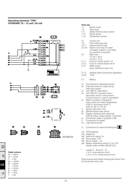
Operating elements ”TRS”<br />
<strong>HYDRONIC</strong> 10 – 12 volt / 24 volt<br />
Parts list<br />
1.1 Burner motor<br />
1.2 Glow plug<br />
1.5 Safety thermal cutout switch<br />
1.12 Flame sensor<br />
1.13 Temperature sensor<br />
2.1 Control unit<br />
2.2 Fuel metering pump<br />
2.5.7 Vehicle blower relay<br />
2.5.18 Switch-over relay for water<br />
circulation system, to be fitted<br />
by customer if required<br />
2.7 Main fuse<br />
12 volt = 20 A<br />
24 volt = 15 A<br />
2.7.1 Fuse for control switch 5 A<br />
2.7.5 Fuse for vehicle blower 25 A<br />
2.12 Water pump<br />
(max. additional load: 4 A)<br />
3.1.2 Heating switch (continuous operation)<br />
3.2.9 Timer<br />
5.1 Battery<br />
a) Connection for operating device<br />
b) External control for water pump<br />
(with plus signal)<br />
c) with TRS D+ (alternator)<br />
d) with TRS HA– (auxiliary drive /<br />
secondary drive) / minus switch<br />
Connect lead to + pole if unavailable<br />
e) Water circulation changeover:<br />
relay closes at a water temperature<br />
of 68 °C and opens at 63 °C<br />
(with D+ 58 °C / 45 °C)<br />
f) Ignition (terminal +15)<br />
g) Vehicle blower step switch<br />
h) Display, flashing code (optional)<br />
(LED at choice, series resistor 1.5 kohms)<br />
k) Connection leads in plug B2 or B6<br />
l) Connection for heater<br />
m) Light (terminal 58)<br />
n) Connection for external heating key<br />
D<br />
S<br />
GB<br />
F<br />
Cable colours<br />
sw = black<br />
ws = white<br />
rt = red<br />
ge = yellow<br />
gn = green<br />
vi = violet<br />
br = brown<br />
gr = grey<br />
bl = blue<br />
li = lila<br />
2044601B.<br />
a1) TRS feedback<br />
a2) Diagnosis<br />
a3) Switch-on signal, S+<br />
a4) Plus supply, +30<br />
a5) Minus supply, –31<br />
a6) Battery separating switch (+) on / off<br />
(diode: order number 208 00 012)<br />
* Length A – B and C – D:<br />
< 5 m: cross-section 4 mm 2<br />
> 5 m < 8 m: cross-section 6 mm 2<br />
Plug housing and socket housing are shown from<br />
the conductor entry side<br />
20