Instruction Bulletin I - Pressure Switch Instruments - Gems Sensors
Instruction Bulletin I - Pressure Switch Instruments - Gems Sensors
Instruction Bulletin I - Pressure Switch Instruments - Gems Sensors

You also want an ePaper? Increase the reach of your titles
YUMPU automatically turns print PDFs into web optimized ePapers that Google loves.
L1 L2 Earth<br />
120 GND<br />
VAC Grounded<br />
D-2: Wiring Diagram<br />
Non-Intrinsically Safe Wiring<br />
Metal Conduit Hub<br />
Grounded<br />
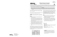
D-3: Auxillary Relay Slide <strong>Switch</strong><br />
Horn<br />
Cutoff Alarm<br />
Slide<br />
<strong>Switch</strong><br />
Non-Hazardous Area<br />
Hazardous Area<br />
Class I Groups A, B, C, D<br />
Class II Groups E, F, G<br />
Class III, Division 1<br />
Hazardous Locations<br />
L1 L2 Gnd NC C NO<br />
S2 Gnd<br />
Auxiliary Contacts<br />
Gnd S1<br />
UL Listed Seal Off Fitting<br />
Intrinsically Safe Wiring<br />
Sensor 1<br />
Sensor 2<br />
Operation<br />
Dry Contact Operation: The green LED will light when power is<br />
applied to the unit. When either sensor contact switches<br />
state(fault condition), the horn will activate and the appropriate<br />
red LED will light. On pressing the acknowledge pushbutton,<br />
the horn will silence. The red LED will remain lit as long as the<br />
fault condition is present. On correcting the fault condition, the<br />
red LED will automatically clear.<br />
If one of the channels has detected a fault and has been<br />
acknowledged, and the other sensor detects a fault, the appropriate<br />
red LED will light and the horn will again activate. The red<br />
LED will remain lit as long as the fault condition is present. On<br />
correcting the fault condition, the red LED will automatically clear.<br />
Test Button<br />
Pushing the test button allows you to test the alarm panel<br />
circuitry. On pushing the test button, the horn will activate, both<br />
red LED’s will light and the auxiliary relay will activate. On<br />
releasing the test button, the horn, red LED’s and auxiliary relay<br />
will deactivate.<br />
Auxiliary Relay Operation<br />
Model TA-732X0 contains an auxiliary relay for remote indication<br />
of a fault condition. The contact configuration shown in Diagram<br />
D-2, shows the position of the contacts in the non-fault<br />
condition. The relay can be field set to either a “cut-off” mode or<br />
“alarm” mode. In “cut-off” mode, only channel 1 will activate the<br />
Backside of Lid<br />
Circuit<br />
Board<br />
auxiliary relay. The relay will mimic the red LED or fault<br />
condition. The relay will activate on fault condition,<br />
changing the state of the contacts. To deactivate the<br />
relay, you must clear the fault condition. Pressing the<br />
acknowledge button will not deactivate the relay. In<br />
“alarm” mode, the relay will mimic the horn. The relay<br />
will activate on fault condition indicated by either channel,<br />
changing the state of the contacts. To deactivate<br />
the relay, either press the acknowledge button or clear<br />
the fault condition. If the second channel detects a fault<br />
condition after the first channel has been acknowledged,<br />
the auxiliary contact will again activate. To deactivate<br />
the relay, either press the acknowledge button or clear<br />
the fault condition. On models TA732X1 and TA-732X2,<br />
the auxiliary relay is preset at the Factory and is not<br />
field adjustable.<br />
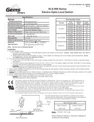
Alarm 1 Power Alarm 2<br />
(Red) (Green) (Red)<br />
Test<br />
Model Number<br />
TA 73 X X X<br />
TA-732<br />
Acknowledge<br />
Optional Character<br />
0 - No option<br />
Adjust volume by<br />
rotating shutter<br />
Interface Contact (both same)<br />
A - N.O. dry contacts (close on fault)<br />
B - N.C. dry contacts (open on fault)<br />
Number of Channels<br />
2 - Two channel unit<br />
Monitoring Panel<br />
<strong>Gems</strong> <strong>Sensors</strong> Inc.<br />
One Cowles Road<br />
Plainville, CT 06062-1198<br />
Tel: 860-793-4579<br />
Fax: 860-793-4580