Series 1 Part Numbers - Pressure Switch Instruments - Gems Sensors
Series 1 Part Numbers - Pressure Switch Instruments - Gems Sensors
Series 1 Part Numbers - Pressure Switch Instruments - Gems Sensors

Create successful ePaper yourself
Turn your PDF publications into a flip-book with our unique Google optimized e-Paper software.
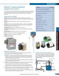
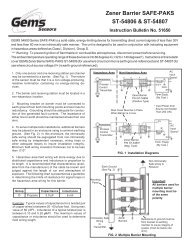
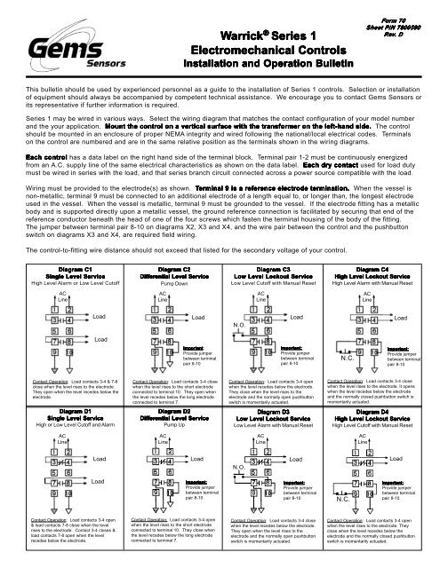
Warrick<br />
® <strong>Series</strong> 1<br />
Electromechanical Controls<br />
Installation and Operation Bulletin<br />
Form 70<br />
Sheet P/N 7800590<br />
Rev. . D<br />
This bulletin should be used by experienced personnel as a guide to the installation of <strong>Series</strong> 1 controls. Selection or installation<br />
of equipment should always be accompanied by competent technical assistance. We encourage you to contact <strong>Gems</strong> <strong>Sensors</strong> or<br />
its representative if further information is required.<br />
<strong>Series</strong> 1 may be wired in various ways. Select the wiring diagram that matches the contact configuration of your model number<br />
and the your application. Mount the control on a vertical surface with the transformer on the left-hand side. The control<br />
should be mounted in an enclosure of proper NEMA integrity and wired following the national/local electrical codes. Terminals<br />
on the control are numbered and are in the same relative position as the terminals shown in the wiring diagrams.<br />
Each control has a data label on the right hand side of the terminal block. Terminal pair 1-2 must be continuously energized<br />
from an A.C. supply line of the same electrical characteristics as shown on the data label. Each dry contact used for load duty<br />
must be wired in series with the load, and that series branch circuit connected across a power source compatible with the load.<br />
Wiring must be provided to the electrode(s) as shown. Terminal 9 is a reference electrode termination. When the vessel is<br />
non-metallic, terminal 9 must be connected to an additional electrode of a length equal to, or longer than, the longest electrode<br />
used in the vessel. When the vessel is metallic, terminal 9 must be grounded to the vessel. If the electrode fitting has a metallic<br />
body and is supported directly upon a metallic vessel, the ground reference connection is facilitated by securing that end of the<br />
reference conductor beneath the head of one of the four screws which fasten the terminal housing of the body of the fitting.<br />
The jumper between terminal pair 8-10 on diagrams X2, X3 and X4, and the wire pair between the control and the pushbutton<br />
switch on diagrams X3 and X4, are required field wiring.<br />
The control-to-fitting wire distance should not exceed that listed for the secondary voltage of your control.<br />
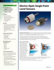
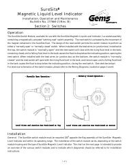
Diagram C1<br />
Single Level Service<br />
High Level Alarm or Low Level Cutoff<br />
Diagram C2<br />
Differential Level Service<br />
Pump Down<br />
Diagram C3<br />
Low Level Lockout Service<br />
Low Level Cutoff with Manual Reset<br />
Diagram C4<br />
High Level Lockout Service<br />
High Level Alarm with Manual Reset<br />
AC<br />
Line<br />
AC<br />
Line<br />
AC<br />
Line<br />
AC<br />
Line<br />
Load<br />
Load<br />
N.O.<br />
Load<br />
Load<br />
Load<br />
Important:<br />
Provide jumper<br />
between terminal<br />
pair 8-10<br />
Important:<br />
Provide jumper<br />
between terminal<br />
pair 8-10<br />
N.C.<br />
Important:<br />
Provide jumper<br />
between terminal<br />
pair 8-10<br />
Contact Operation: Load contacts 3-4 & 7-8<br />
close when the level rises to the electrode.<br />
They open when the level recedes below the<br />
electrode.<br />
Contact Operation: Load contacts 3-4 close<br />
when the level rises to the short electrode<br />
connected to terminal 10. They open when<br />
the level recedes below the long electrode<br />
connected to terminal 7.<br />
Contact Operation: Load contacts 3-4 open<br />
when the level recedes below the electrode.<br />
They close when the level rises to the<br />
electrode and the normally open pushbutton<br />
switch is momentarily actuated.<br />
Contact Operation: Load contacts 3-4 close<br />
when the level rises to the electrode. It opens<br />
when the level recedes below the electrode<br />
and the normally closed pushbutton switch is<br />
momentarily actuated.<br />
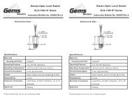
Diagram D1<br />
Single Level Service<br />
High or Low Level Cutoff and Alarm<br />
Diagram D2<br />
Differential Level Service<br />
Pump Up<br />
Diagram D3<br />
Low Level Lockout Service<br />
Low Level Alarm with Manual Reset<br />
Diagram D4<br />
High Level Lockout Service<br />
High Level Cutoff with Manual Reset<br />
AC<br />
Line<br />
AC<br />
Line<br />
AC<br />
Line<br />
AC<br />
Line<br />
Load<br />
Load<br />
N.O.<br />
Load<br />
Load<br />
Load<br />
Important:<br />
Provide jumper<br />
between terminal<br />
pair 8-10<br />
Important:<br />
Provide jumper<br />
between terminal<br />
pair 8-10<br />
N.C.<br />
Important:<br />
Provide jumper<br />
between terminal<br />
pair 8-10<br />
Contact Operation: Load contacts 3-4 open<br />
& load contacts 7-8 close when the level<br />
rises to the electrode. Contact 3-4 closes &<br />
load contacts 7-8 open when the level<br />
recedes below the electrode.<br />
Contact Operation: Load contacts 3-4 open<br />
when the level rises to the short electrode<br />
connected to terminal 10. They close when<br />
the level recedes below the long electrode<br />
connected to terminal 7.<br />
Contact Operation: Load contacts 3-4 close<br />
when the level recedes below the electrode.<br />
They open when the level rises to the<br />
electrode and the normally open pushbutton<br />
switch is momentarily actuated.<br />
Contact Operation: Load contacts 3-4 open<br />
when the level rises to the electrode. They<br />
close when the level recedes below the<br />
electrode and the normally closed pushbutton<br />
switch is momentarily actuated.
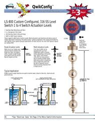
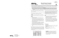
<strong>Series</strong> 1 X - X - X - X<br />
Contact Configuration<br />
C<br />
D<br />
E<br />
F<br />
G<br />
H<br />
J<br />
N.O.<br />
2<br />
1<br />
0<br />
3<br />
2<br />
1<br />
0<br />
N.C.<br />
0<br />
1<br />
2<br />
0<br />
1<br />
2<br />
3<br />
AC Line Voltage<br />
1 115 VAC<br />
2 230 VAC<br />
4 460 VAC<br />
5 575 VAC<br />
6 115/230 VAC<br />
7 24 VAC<br />
9 380 VAC<br />
A<br />
B<br />
C<br />
D<br />
E<br />
Secondary Voltage<br />
Sec. Volts<br />
25<br />
75<br />
150<br />
300<br />
500<br />
Sensitivity<br />
50<br />
450<br />
1.5 K<br />
7.0 K<br />
20.0 K<br />
Dist/Ft.<br />
75,000<br />
7,500<br />
1,750<br />
500<br />
150<br />
Enclosures<br />
For on-board reset switches, add suffix letter “A” for normally open switch<br />
and letter “C” for normally closed switch<br />
0<br />
1<br />
4<br />
7<br />
None<br />
NEMA 1<br />
NEMA 4<br />
NEMA 7<br />
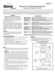
Diagram F1<br />
Single Level Service<br />
High Level Alarm or Low Level Cutoff<br />
AC<br />
Line<br />
Diagram F2<br />
Differential Level Service<br />
Pump Down<br />
AC<br />
Line<br />
Diagram F3<br />
Low Level Lockout Service<br />
Low Level Cutoff with Manual Reset<br />
AC<br />
Line<br />
Diagram F4<br />
High Level Lockout Service<br />
High Level Alarm with Manual Reset<br />
AC<br />
Line<br />
Load<br />
Load<br />
Load<br />
Load<br />
Load<br />
Important:<br />
Provide jumper<br />
between terminal<br />
pair 8-10<br />
Load<br />
Load<br />
Important:<br />
Provide jumper<br />
between terminal<br />
pair 8-10<br />
Load<br />
Load<br />
Important:<br />
Provide jumper<br />
between terminal<br />
pair 8-10<br />
Contact Operation: Load contacts 3-4 & 5-6<br />
& 7-8 close when the level rises to the<br />
electrode. They open when the level recedes<br />
below the electrode.<br />
Contact Operation: Load contacts 3-4 & 5-6<br />
close when the level rises to the short<br />
electrode connected to terminal 10. They<br />
open when the level recedes below the long<br />
electrode connected to terminal 7.<br />
Contact Operation: Load contacts 3-4 & 5-6<br />
open when the level recedes below the<br />
electrode. Then close when the level rises to<br />
the electrode and the normally open<br />
pushbutton switch is momentarily actuated.<br />
Contact Operation: Load contacts 3-4 & 5-6<br />
close when the level rises to the electrode.<br />
Then open when the level recedes below the<br />
electrode and the normally closed pushbutton<br />
switch is momentarily actuated.<br />
Diagram G1<br />
Single Level Service<br />
High or Low Level Cutoff and Alarm<br />
AC<br />
Line<br />
Diagram G2<br />
Differential Level Service<br />
Pump Down or Pump Up<br />
AC<br />
Line<br />
Diagram G3<br />
Low Level Lockout Service<br />
L.L Cutoff & Alarm with Manual Reset<br />
AC<br />
Line<br />
Diagram G4<br />
High Level Lockout Service<br />
H.L. Cutoff & Alarm with Manual Reset<br />
AC<br />
Line<br />
Load<br />
Load<br />
Load<br />
Load<br />
Load<br />
Load<br />
Load<br />
Load<br />
Load<br />
Important:<br />
Provide jumper<br />
between terminal<br />
pair 8-10<br />
Important:<br />
Provide jumper<br />
between terminal<br />
pair 8-10<br />
Important:<br />
Provide jumper<br />
between terminal<br />
pair 8-10<br />
Contact Operation: Load contacts 3-4 open &<br />
5-6 & 7-8 close when the level rises to the<br />
electrode. Load contacts 3-4 closes and<br />
contacts 5-6 & 7-8 open when the level<br />
recedes below the electrode.<br />
Contact Operation: Load contacts 3-4 open &<br />
contacts 5-6 close when the level rises to the<br />
short electrode connected to terminal 10.<br />
Contacts 3-4 close & contacts 5-6 open when<br />
the level recedes below the long electrode<br />
connected to terminal 7.<br />
Contact Operation: Load contacts 3-4 close &<br />
5-6 open when the level recedes below the<br />
electrode. Contacts 3-4 open & contacts 5-6<br />
close when the level rises to the electrode and<br />
the normally open pushbutton switch is<br />
momentarily actuated.<br />
Contact Operation: Load contacts 3-4 open<br />
and contacts 5-6 close when the level rises to<br />
the electrode. Contacts 3-4 close & contacts<br />
5-6 open when the level recedes below the<br />
electrode and the normally closed pushbutton<br />
switch is momentarily actuated.<br />
Diagram H1<br />
Single Level Service<br />
High or Low Level Cutoff and Alarm<br />
Diagram H2<br />
Differential Level Service<br />
Pump Up<br />
Diagram H3<br />
Low Level Lockout Service<br />
Low Level Alarm with Manual Reset<br />
Diagram H4<br />
High Level Lockout Service<br />
High Level Cutoff with Manual Reset<br />
Load<br />
Load<br />
Load<br />
Load<br />
Load<br />
Load<br />
Load<br />
Load<br />
Load<br />
Important:<br />
Provide jumper<br />
between terminal<br />
pair 8-10<br />
Important:<br />
Provide jumper<br />
between terminal<br />
pair 8-10<br />
Important:<br />
Provide jumper<br />
between terminal<br />
pair 8-10<br />
Contact Operation: Load contacts 3-4 & 5-6<br />
open and 7-8 close when the level rises to the<br />
electrode. Load contacts 3-4 & 5-6 close and<br />
contacts 7-8 open when the level recedes<br />
below the electrode.<br />
Contact Operation: Load contacts 3-4 & 5-6<br />
open when the level rises to the short<br />
electrode connected to terminal 10. They<br />
close when the level recedes below the long<br />
electrode connected to terminal 7.<br />
Contact Operation: Load contacts 3-4 & 5-6<br />
close when the level recedes below the<br />
electrode. Then open when the level rises to<br />
the electrode and the normally open<br />
pushbutton switch is momentarily actuated.<br />
Contact Operation: Load contacts 3-4 & 5-6<br />
open when the level rises to the electrode.<br />
Then close when the level recedes below the<br />
electrode and the normally closed pushbutton<br />
switch is momentarily actuated.<br />
<strong>Gems</strong> <strong>Sensors</strong> Inc.<br />
One Cowles Road<br />
Plainville, CT 06062-1198<br />
Tel: 860-793-4579<br />
Fax: 860-793-4580