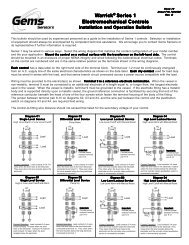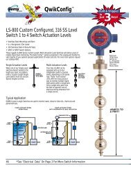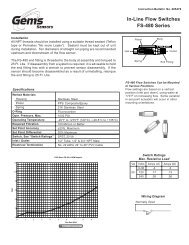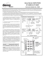
Instruction Bulletin I - Pressure Switch Instruments - Gems Sensors
Instruction Bulletin I - Pressure Switch Instruments - Gems Sensors
Instruction Bulletin I - Pressure Switch Instruments - Gems Sensors

You also want an ePaper? Increase the reach of your titles
YUMPU automatically turns print PDFs into web optimized ePapers that Google loves.
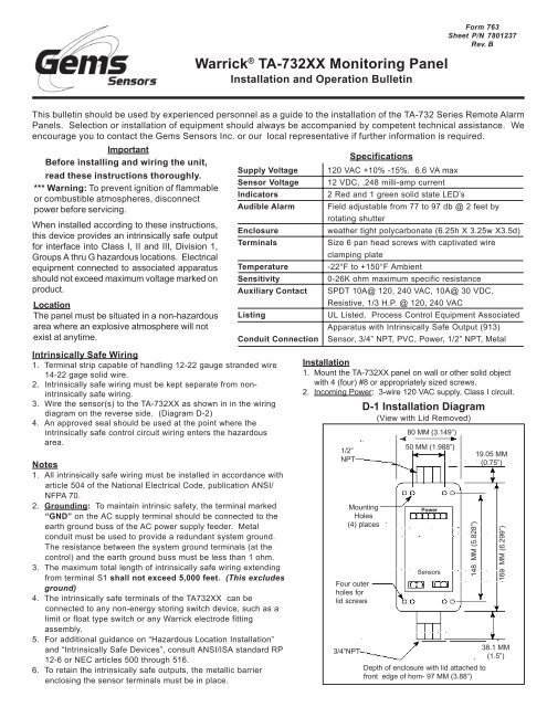
Warrick ® TA-732XX Monitoring Panel<br />
Installation and Operation <strong>Bulletin</strong><br />
Form 763<br />
Sheet P/N 7801237<br />
Rev. B<br />
This bulletin should be used by experienced personnel as a guide to the installation of the TA-732 Series Remote Alarm<br />
Panels. Selection or installation of equipment should always be accompanied by competent technical assistance. We<br />
encourage you to contact the <strong>Gems</strong> <strong>Sensors</strong> Inc. or our local representative if further information is required.<br />
Important<br />
Before installing and wiring the unit,<br />
read these instructions thoroughly.<br />
*** Warning: To prevent ignition of flammable<br />
or combustible atmospheres, disconnect<br />
power before servicing.<br />
When installed according to these instructions,<br />
this device provides an intrinsically safe output<br />
for interface into Class I, II and III, Division 1,<br />
Groups A thru G hazardous locations. Electrical<br />
equipment connected to associated apparatus<br />
should not exceed maximum voltage marked on<br />
product.<br />
Location<br />
The panel must be situated in a non-hazardous<br />
area where an explosive atmosphere will not<br />
exist at anytime.<br />
Supply Voltage<br />
Sensor Voltage<br />
Indicators<br />
Audible Alarm<br />
Enclosure<br />
Terminals<br />
Temperature<br />
Sensitivity<br />
Auxiliary Contact<br />
Listing<br />
Conduit Connection<br />
Intrinsically Safe Wiring<br />
1. Terminal strip capable of handling 12-22 gauge stranded wire<br />
14-22 gage solid wire.<br />
2. Intrinsically safe wiring must be kept separate from nonintrinsically<br />
safe wiring.<br />
3. Wire the sensor(s) to the TA-732XX as shown in in the wiring<br />
diagram on the reverse side. (Diagram D-2)<br />
4. An approved seal should be used at the point where the<br />
intrinsically safe control circuit wiring enters the hazardous<br />
area.<br />
Notes<br />
1. All intrinsically safe wiring must be installed in accordance with<br />
article 504 of the National Electrical Code, publication ANSI/<br />
NFPA 70.<br />
2. Grounding: To maintain intrinsic safety, the terminal marked<br />
“GND” on the AC supply terminal should be connected to the<br />
earth ground buss of the AC power supply feeder. Metal<br />
conduit must be used to provide a redundant system ground.<br />
The resistance between the system ground terminals (at the<br />
control) and the earth ground buss must be less than 1 ohm.<br />
3. The maximum total length of intrinsically safe wiring extending<br />
from terminal S1 shall not exceed 5,000 feet. (This excludes<br />
ground)<br />
4. The intrinsically safe terminals of the TA732XX can be<br />
connected to any non-energy storing switch device, such as a<br />
limit or float type switch or any Warrick electrode fitting<br />
assembly.<br />
5. For additional guidance on “Hazardous Location Installation”<br />
and “Intrinsically Safe Devices”, consult ANSI/ISA standard RP<br />
12-6 or NEC articles 500 through 516.<br />
6. To retain the intrinsically safe outputs, the metallic barrier<br />
enclosing the sensor terminals must be in place.<br />
120 VAC +10% -15%. 6.6 VA max<br />
12 VDC, .248 milli-amp current<br />
2 Red and 1 green solid state LED’s<br />
Field adjustable from 77 to 97 db @ 2 feet by<br />
rotating shutter<br />
weather tight polycarbonate (6.25h X 3.25w X3.5d)<br />
Size 6 pan head screws with captivated wire<br />
clamping plate<br />
-22°F to +150°F Ambient<br />
0-26K ohm maximum specific resistance<br />
SPDT 10A@ 120, 240 VAC, 10A@ 30 VDC,<br />
Resistive, 1/3 H.P. @ 120, 240 VAC<br />
UL Listed, Process Control Equipment Associated<br />
Apparatus with Intrinsically Safe Output (913)<br />
Sensor, 3/4” NPT, PVC, Power, 1/2” NPT, Metal<br />
Installation<br />
1. Mount the TA-732XX panel on wall or other solid object<br />
with 4 (four) #8 or appropriately sized screws.<br />
2. Incoming Power: 3-wire 120 VAC supply, Class I circuit.<br />
1/2”<br />
NPT<br />
Mounting<br />
Holes<br />
(4) places<br />
Four outer<br />
holes for<br />
lid screws<br />
3/4”NPT<br />
Specifications<br />
D-1 Installation Diagram<br />
(View with Lid Removed)<br />
80 MM (3.149”)<br />
50 MM (1.988”)<br />
Power<br />
<strong>Sensors</strong><br />
148 MM (5.828”)<br />
Depth of enclosure with lid attached to<br />
front edge of horn- 97 MM (3.88”)<br />
19.05 MM<br />
(0.75”)<br />
160 MM (6.299”)<br />
38.1 MM<br />
(1.5”)
L1 L2 Earth<br />
120 GND<br />
VAC Grounded<br />
D-2: Wiring Diagram<br />
Non-Intrinsically Safe Wiring<br />
Metal Conduit Hub<br />
Grounded<br />
D-3: Auxillary Relay Slide <strong>Switch</strong><br />
Horn<br />
Cutoff Alarm<br />
Slide<br />
<strong>Switch</strong><br />
Non-Hazardous Area<br />
Hazardous Area<br />
Class I Groups A, B, C, D<br />
Class II Groups E, F, G<br />
Class III, Division 1<br />
Hazardous Locations<br />
L1 L2 Gnd NC C NO<br />
S2 Gnd<br />
Auxiliary Contacts<br />
Gnd S1<br />
UL Listed Seal Off Fitting<br />
Intrinsically Safe Wiring<br />
Sensor 1<br />
Sensor 2<br />
Operation<br />
Dry Contact Operation: The green LED will light when power is<br />
applied to the unit. When either sensor contact switches<br />
state(fault condition), the horn will activate and the appropriate<br />
red LED will light. On pressing the acknowledge pushbutton,<br />
the horn will silence. The red LED will remain lit as long as the<br />
fault condition is present. On correcting the fault condition, the<br />
red LED will automatically clear.<br />
If one of the channels has detected a fault and has been<br />
acknowledged, and the other sensor detects a fault, the appropriate<br />
red LED will light and the horn will again activate. The red<br />
LED will remain lit as long as the fault condition is present. On<br />
correcting the fault condition, the red LED will automatically clear.<br />
Test Button<br />
Pushing the test button allows you to test the alarm panel<br />
circuitry. On pushing the test button, the horn will activate, both<br />
red LED’s will light and the auxiliary relay will activate. On<br />
releasing the test button, the horn, red LED’s and auxiliary relay<br />
will deactivate.<br />
Auxiliary Relay Operation<br />
Model TA-732X0 contains an auxiliary relay for remote indication<br />
of a fault condition. The contact configuration shown in Diagram<br />
D-2, shows the position of the contacts in the non-fault<br />
condition. The relay can be field set to either a “cut-off” mode or<br />
“alarm” mode. In “cut-off” mode, only channel 1 will activate the<br />
Backside of Lid<br />
Circuit<br />
Board<br />
auxiliary relay. The relay will mimic the red LED or fault<br />
condition. The relay will activate on fault condition,<br />
changing the state of the contacts. To deactivate the<br />
relay, you must clear the fault condition. Pressing the<br />
acknowledge button will not deactivate the relay. In<br />
“alarm” mode, the relay will mimic the horn. The relay<br />
will activate on fault condition indicated by either channel,<br />
changing the state of the contacts. To deactivate<br />
the relay, either press the acknowledge button or clear<br />
the fault condition. If the second channel detects a fault<br />
condition after the first channel has been acknowledged,<br />
the auxiliary contact will again activate. To deactivate<br />
the relay, either press the acknowledge button or clear<br />
the fault condition. On models TA732X1 and TA-732X2,<br />
the auxiliary relay is preset at the Factory and is not<br />
field adjustable.<br />
Alarm 1 Power Alarm 2<br />
(Red) (Green) (Red)<br />
Test<br />
Model Number<br />
TA 73 X X X<br />
TA-732<br />
Acknowledge<br />
Optional Character<br />
0 - No option<br />
Adjust volume by<br />
rotating shutter<br />
Interface Contact (both same)<br />
A - N.O. dry contacts (close on fault)<br />
B - N.C. dry contacts (open on fault)<br />
Number of Channels<br />
2 - Two channel unit<br />
Monitoring Panel<br />
<strong>Gems</strong> <strong>Sensors</strong> Inc.<br />
One Cowles Road<br />
Plainville, CT 06062-1198<br />
Tel: 860-793-4579<br />
Fax: 860-793-4580