SureSiteā Magnetic Liquid Level Indicator - Pressure Switch ...
SureSiteā Magnetic Liquid Level Indicator - Pressure Switch ...
SureSiteā Magnetic Liquid Level Indicator - Pressure Switch ...

Create successful ePaper yourself
Turn your PDF publications into a flip-book with our unique Google optimized e-Paper software.
Operation<br />
SureSite â<br />
<strong>Magnetic</strong> <strong>Liquid</strong> <strong>Level</strong> <strong>Indicator</strong><br />
Installation, Operation and Maintenance<br />
Bulletin No. 177664-2 (Rev. B)<br />
Section 2: <strong>Switch</strong>es<br />
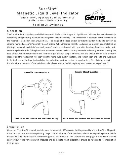
The SureSite <strong>Switch</strong> Module, available for use with the SureSite <strong>Magnetic</strong> <strong>Liquid</strong> <strong>Level</strong> <strong>Indicator</strong>, is a sealed assembly<br />
containing a magnetically actuated “latching-reed” switch assembly. The reed switch is actuated by the movement of<br />
the magnet contained in the SureSite float. The design of the reed switch permits the switch module to perform as<br />
either a “normally open” or “normally closed” switch. When installed with the lead wires (or junction box) installed at<br />
the top, the switch module is “normally open” and the reed switch will close with the rising fluid level in the tank;<br />
remaining closed until a falling fluid level in the tank causes the float to drop below the indicating position, opening the<br />
reed switch. When installed with the lead wires (or junction box) at the bottom, the switch module is “normally<br />
closed” and the reed switch will open with the rising fluid level in the tank, and remain open until a falling fluid level<br />
in the tank causes the float to drop below the indicating position, closing the reed switch. (See sketches below)<br />
For electrical schematics of the switch module, please refer to the Wiring Diagrams, located on pages 5 and 6.<br />
- Normally Open Operation - - Normally Closed Operation -<br />
Lead Wires and Junction Box Positioned at Top<br />
op<br />
Lead Wires and Junction Box Positioned at Bottom<br />
Installation<br />
General: The SureSite switch module must be mounted 180 o opposite the flag assembly of the SureSite <strong>Magnetic</strong><br />
<strong>Level</strong> <strong>Indicator</strong> and within its operating range. The installation of the switch module varies, depending on the switch<br />
module housing and the type of SureSite <strong>Magnetic</strong> <strong>Level</strong> <strong>Indicator</strong>. The chart on the next page is intended to provide<br />
an overview of the various switch modules and to indicate which diagram(s) should be referred to for installation<br />
instructions.<br />
1 of 6
Installation (Cont.)<br />
If it is necessary to locate two switch-points close together, two switch modules can be positioned<br />
side-by-side and located 180 o opposite of the flag assembly, as shown.<br />
Flag<br />
Assembly<br />
Top View<br />
Part<br />
Number<br />
85350<br />
86435<br />
86567<br />
87480<br />
80469<br />
83140<br />
83150<br />
84320<br />
803430<br />
83100*<br />
83110*<br />
83120*<br />
83130*<br />
84330<br />
SureSite<br />
Type<br />
Standard<br />
Standard<br />
Mini<br />
Mini / Plastic<br />
Plastic<br />
All<br />
All<br />
All<br />
All<br />
All<br />
All<br />
All<br />
All<br />
All<br />
<strong>Switch</strong> Rating /<br />
Configuration<br />
20 VA SPST, N.O. or N.C. 300 / 148<br />
20 VA SPST, N.O. or N.C. 300 / 148<br />
20 VA SPST, N.O. or N.C. 300 / 148<br />
20 VA SPST, N.O. or N.C. 300 / 148<br />
20 VA SPST, N.O. or N.C. 300 / 148<br />
High Temperature<br />
20 VA SPST, N.O. or N.C.<br />
20 VA SPST, N.O. or N.C.<br />
20 VA SPDT, N.O. or N.C.<br />
220 VDC, 5 Amp<br />
750 / 398<br />
750 / 398<br />
750 / 398<br />
750 / 398<br />
Incl.<br />
Incl.<br />
Incl.<br />
Incl.<br />
Explosion-Proof / High Temperature<br />
120 VDC, 10 Amp<br />
24 VDC, 10 Amp<br />
20 VA SPST, N.O. or N.C.<br />
20 VA SPST, N.O. or N.C.<br />
20 VA SPDT, N.O. or N.C.<br />
<strong>Switch</strong> Modules<br />
Max. Fluid<br />
Temp (°F / °C)<br />
Standard<br />
750 / 398<br />
750 / 398<br />
750 / 398<br />
750 / 398<br />
750 / 398<br />
Mounting Hardware<br />
Bracket / Spacer<br />
Clamp J-Box<br />
Block<br />
N/A<br />
N/A<br />
N/A<br />
N/A<br />
N/A<br />
Incl.<br />
Incl.<br />
Incl.<br />
Incl.<br />
Incl.<br />
N/A<br />
Incl.<br />
Incl.<br />
N/A<br />
N/A<br />
N/A<br />
N/A<br />
N/A<br />
Incl.<br />
Incl.<br />
Incl.<br />
Incl.<br />
Incl.<br />
Incl.<br />
N/A<br />
N/A<br />
N/A<br />
N/A<br />
N/A<br />
N/A<br />
N/A<br />
N/A<br />
Incl.<br />
Incl.<br />
Incl.<br />
Incl.<br />
Incl.<br />
Incl.<br />
Polysulfone<br />
Polysulfone<br />
Polysulfone<br />
Polysulfone<br />
Polysulfone<br />
316 SS<br />
316 SS<br />
316 SS<br />
316 SS<br />
316 SS<br />
316 SS<br />
316 SS<br />
316 SS<br />
316 SS<br />
*Factory Mutual approved for:<br />
Explosion-proof for Class 1, Division 1, Groups C & D and Class 1, Division 2, Groups B, C & D; Dust ignition proof per Class<br />
2, Division 1, Groups E, F & G and suitable for Class 3, Division 1, Hazardous Location, Indoors (Ref. File #J.I. 0A8A3.AE).<br />
Also CSA certified for Class 1, Division 1, Groups B, C & D (Ref. Files LR22666-22 and LR22666-24).<br />
Note<br />
For Standard Unit installation instructions, see Mounting Diagram “A”<br />
For all other part numbers listed above, see Mounting diagram “B”, “C” or “D”<br />
<strong>Switch</strong><br />
Housing<br />
Material<br />
2 of 6
- Mounting Diagrams -<br />
Diagram A<br />
Standard SureSite ®<br />
<strong>Switch</strong> Part Numbers<br />
80469, 85350, 86435, 86567, 87480<br />
1. Position the switch module 180° from<br />
the flag assembly and within indicating<br />
range.<br />
2. Slide the switch clamp between the<br />
flag assembly and the weldment of your<br />
SureSite <strong>Magnetic</strong> <strong>Level</strong> <strong>Indicator</strong>.<br />
3. With the switch module located at the<br />
desired fluid level, tighten the clamp<br />
screw securely; not to exceed a torque of<br />
10 lb-inches.<br />
4. Connect the switch module leads to the load<br />
circuit.<br />
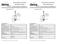
Diagram B<br />
1. Position the switch module 180° from<br />
the flag assembly and within indicating<br />
range.<br />
2. Slide the tabs of the switch clamps<br />
between the flag assembly and the<br />
weldment of the Mini SureSite <strong>Magnetic</strong><br />
<strong>Level</strong> <strong>Indicator</strong>; wrapping the retaining<br />
screw-end around the upper and lower<br />
stem of the switch, as shown.<br />
3. With the switch module located at the<br />
desired fluid level, tighten the clamp<br />
screw securely; not to exceed a torque of<br />
120 lb-inches.<br />
<strong>Switch</strong><br />
Part Numbers<br />
83100, 83110,<br />
83120, 83130.<br />
83140, 83150,<br />
84320, 84330<br />
Mini SureSite ®<br />
Flag<br />
Assembly<br />
Õ<br />
2-1/2”<br />
Ref.<br />
Õ<br />
1-1/4”<br />
O.D.<br />
Tubing<br />
1-1/4”<br />
O.D.<br />
Tubing<br />
<strong>Switch</strong><br />
Module<br />
#24 Clamp<br />
(P/N 85576)<br />
-2 Required<br />
J-Box Not<br />
Included<br />
On Type<br />
83140<br />
4. Connect the switch module leads to the<br />
load circuit.<br />
<strong>Switch</strong><br />
Part Numbers<br />
83150, 84320<br />
Flag<br />
Assembly<br />
Õ<br />
2-1/2”<br />
Ref.<br />
<strong>Switch</strong><br />
Module<br />
Õ<br />
#24 Clamp<br />
(P/N 85576)<br />
-2 Required<br />
3 of 6
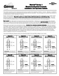
Mounting Diagrams (Cont.)<br />
Diagram C<br />
1. Slide the switch into the support<br />
bracket.<br />
2. Position the switch module 180° from<br />
the flag assembly and within indicating<br />
range.<br />
<strong>Switch</strong><br />
Part Numbers<br />
83100, 83110,<br />
83120, 83130.<br />
83140, 83150,<br />
84320, 84330<br />
Alloy SureSite ®<br />
Flag<br />
Assembly<br />
Tubing<br />
or<br />
Pipe<br />
<strong>Switch</strong><br />
Module<br />
J-Box Not<br />
Included<br />
On Type<br />
83140<br />
3. Slide the switch clamp between the<br />
switch bracket and the stem of the<br />
switch, then between the flag assembly<br />
and the weldment of your SureSite<br />
<strong>Magnetic</strong> <strong>Level</strong> <strong>Indicator</strong>.<br />
4. With the switch module located at<br />
the desired fluid level, tighten this<br />
clamp screw securely, not to exceed a<br />
torque of 120 lb-inches.<br />
5. Connect the switch module leads to<br />
the load circuit.<br />
<strong>Switch</strong><br />
Part Numbers<br />
83150, 84320<br />
#48 Clamp<br />
(P/N 85577)<br />
Flag<br />
Assembly<br />
Tubing<br />
or<br />
Pipe<br />
<strong>Switch</strong><br />
Module<br />
#48 Clamp<br />
(P/N 85577)<br />
Diagram D<br />
1. Slide the switch into the plastic spacer<br />
block.<br />
2. Position the switch module 180° from<br />
the flag assembly.<br />
3. Slide the tabs of the switch clamps<br />
between the flag assembly and the<br />
weldment of your SureSite <strong>Magnetic</strong><br />
<strong>Level</strong> <strong>Indicator</strong>, wrapping the retaining<br />
screw-ends around the stem of the switch,<br />
above and below the spacer block and the<br />
desired indication/activation level, as<br />
shown.<br />
<strong>Switch</strong><br />
Part Numbers<br />
83100, 83110,<br />
83120, 83130.<br />
83140, 83150,<br />
84320, 84330<br />
Plastic SureSite ®<br />
Flag<br />
Assembly<br />
#48 Clamp<br />
(P/N 85577)<br />
Tubing<br />
or<br />
Pipe<br />
<strong>Switch</strong><br />
Module<br />
P/N 802265<br />
Spacer Block<br />
J-Box Not<br />
Included<br />
On Type<br />
83140<br />
4. With the switch module located at the<br />
desired fluid level, tighten both clamp<br />
screws securely, not to exceed a torque of<br />
120 lb-inches.<br />
5. Connect the switch module leads to the<br />
load circuit.<br />
<strong>Switch</strong><br />
Part Numbers<br />
83150, 84320<br />
Flag<br />
Assembly<br />
Tubing<br />
or<br />
Pipe<br />
<strong>Switch</strong><br />
Module<br />
4 of 6<br />
#48 Clamp<br />
(P/N 85577)<br />
P/N 802265<br />
Spacer Block
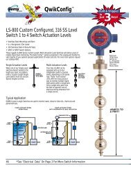
Wiring Diagrams<br />
Part Numbers<br />
80469, 87480, 85350, 86435, 86567<br />
Part Number 83100<br />
- Dry Condition -<br />
SPST, N.O. or N.C. (Dry)<br />
RED<br />
RED<br />
120 VA C<br />
_<br />
+<br />
YELLOW<br />
GREEN<br />
BLUE<br />
ORANGE<br />
BROWN<br />
WHITE<br />
24 VDC<br />
_<br />
+<br />
Part Number 83110<br />
10<br />
- Dry Condition -<br />
Part Numbers<br />
83120, 83140, 83150<br />
- Dry Condition -<br />
2-COND.<br />
CABLE<br />
YELLOW<br />
GREEN<br />
BLUE<br />
ORANGE<br />
BROWN<br />
WHITE<br />
Part Number 83130<br />
- Dry Condition -<br />
Part Numbers<br />
84320, 84330 DPDT<br />
- Dry Condition / J-Box at Top -<br />
3-PIN<br />
TERM<br />
3-PIN<br />
TERM.<br />
3-COND.<br />
CABLE<br />
5 of 6
Wiring Diagrams (Cont.)<br />
Part Numbers<br />
84320, 84330<br />
- Dry Condition / J-Box at BTM -<br />
3-PIN<br />
TERM.<br />
3-COND.<br />
CABLE<br />
<strong>Switch</strong> Module Troubleshooting<br />
Condition<br />
Intermittent <strong>Switch</strong>ing<br />
or<br />
Not Latching<br />
<strong>Switch</strong> Not <strong>Switch</strong>ing<br />
<strong>Switch</strong> Remains Open<br />
or<br />
Closed At All times<br />
Possible Cause<br />
Positioned Incorrectly<br />
<strong>Switch</strong> not in Indicating Range<br />
Incorrect Mounting Hardware<br />
Incorrect Wiring Between<br />
<strong>Switch</strong> & Load<br />
Positioned Incorrectly<br />
<strong>Switch</strong> Not in Indicating Range<br />
Incorrect Mounting Hardware<br />
Incorrect Wiring Between<br />
<strong>Switch</strong> & Load<br />
<strong>Switch</strong> Rating Exceeded<br />
Solution<br />
Reposition <strong>Switch</strong> Modules<br />
Reposition <strong>Switch</strong> Modules<br />
See Appropriate Mounting Diagram<br />
Correct Wiring<br />
(See Wiring Diagrams)<br />
Reposition <strong>Switch</strong> Modules<br />
Reposition <strong>Switch</strong> Modules<br />
See Appropriate Mounting Diagram<br />
Correct Wiring<br />
(See Wiring Diagrams)<br />
Replace <strong>Switch</strong><br />
(See Appropriate Rating Diagram)<br />
6 of 6