GL-8/8U - Ramco Innovations
GL-8/8U - Ramco Innovations
GL-8/8U - Ramco Innovations

You also want an ePaper? Increase the reach of your titles
YUMPU automatically turns print PDFs into web optimized ePapers that Google loves.
INDUCTIVE<br />
PROXIMITY SENSORS<br />
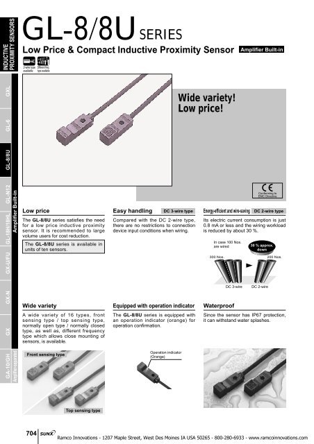
<strong>GL</strong>-8/<strong>8U</strong> SERIES<br />
Low Price & Compact Inductive Proximity Sensor<br />
2-wire type<br />
available<br />
Different freq.<br />
type available<br />
Amplifier Built-in<br />
GXL<br />
<strong>GL</strong>-6<br />
Wide variety!<br />
Low price!<br />
<strong>GL</strong>-8/<strong>8U</strong><br />
GA-10/GH GX GX-N GX-U/FU <strong>GL</strong>-18H/18HL <strong>GL</strong>-N12<br />
Amplifier-separated Amplifier Built-in<br />
Low price<br />
The <strong>GL</strong>-8/<strong>8U</strong> series satisfies the need<br />
for a low price inductive proximity<br />
sensor. It is recommended to large<br />
volume users for cost reduction.<br />
The <strong>GL</strong>-8/<strong>8U</strong> series is available in<br />
units of ten sensors.<br />
Wide variety<br />
A wide variety of 16 types, front<br />
sensing type / top sensing type,<br />
normally open type / normally closed<br />
type, as well as, different frequency<br />
type which allows close mounting of<br />
sensors, is available.<br />
Front sensing type<br />
Easy handling<br />
DC 3-wire type<br />
Compared with the DC 2-wire type,<br />
there are no restrictions to connection<br />
device input conditions when wiring.<br />
Equipped with operation indicator<br />
The <strong>GL</strong>-8/<strong>8U</strong> series is equipped with<br />
an operation indicator (orange) for<br />
operation confirmation.<br />
Operation indicator<br />
(Orange)<br />
Energy-efficient and wire-saving<br />
Its electric current consumption is just<br />
0.8 mA or less and the wiring workload<br />
is reduced by about 30 %.<br />
In case 100 Nos.<br />
are wired<br />
300 Nos. 200 Nos.<br />
DC 3-wire<br />
Waterproof<br />
Conforming to<br />
EMC Directive<br />
DC 2-wire type<br />
30 % approx.<br />
down<br />
DC 2-wire<br />
Since the sensor has IP67 protection,<br />
it can withstand water splashes.<br />
Top sensing type<br />
704
APPLICATIONS<br />
Detecting table over-run<br />
Detecting cam position<br />
<strong>GL</strong>-8/<strong>8U</strong><br />
<strong>GL</strong>-6<br />
GXL<br />
INDUCTIVE<br />
PROXIMITY SENSORS<br />
ORDER GUIDE<br />
DC 3-wire<br />
Top sensing Front sensing<br />
DC 2-wire<br />
Type Appearance (mm in) Sensing range (Note 1) Model No. (Note 2) Output<br />
Front sensing<br />
Top sensing<br />
8<br />
0.315<br />
8<br />
0.315<br />
8<br />
0.315<br />
8<br />
0.315<br />
7.4 0.291<br />
8<br />
0.315<br />
7.4 0.291<br />
8<br />
0.315<br />
24<br />
0.945<br />
24.2<br />
0.953<br />
24<br />
0.945<br />
24.2<br />
0.953<br />
Maximum operation<br />
distance<br />
2.5 mm 0.098 in<br />
(0 to 1.8 mm 0 to 0.071 in)<br />
Stable sensing range<br />
<strong>GL</strong>-8F10<br />
<strong>GL</strong>-8FI10<br />
<strong>GL</strong>-8FB10<br />
<strong>GL</strong>-8FIB10<br />
<strong>GL</strong>-8H10<br />
<strong>GL</strong>-8HI10<br />
<strong>GL</strong>-8HB10<br />
<strong>GL</strong>-8HIB10<br />
<strong>GL</strong>-8FU10<br />
<strong>GL</strong>-8FUI10<br />
<strong>GL</strong>-8FUB10<br />
<strong>GL</strong>-8FUIB10<br />
<strong>GL</strong>-8HU10<br />
<strong>GL</strong>-8HUI10<br />
<strong>GL</strong>-8HUB10<br />
<strong>GL</strong>-8HUIB10<br />
NPN<br />
open-collector<br />
transistor<br />
Non-contact<br />
DC 2-wire type<br />
Output operation<br />
Normally open<br />
Normally closed<br />
Normally open<br />
Normally closed<br />
Normally open<br />
Normally closed<br />
Normally open<br />
Normally closed<br />
Notes: 1) The maximum operation distance stands for the maximum distance for which the sensor can detect the standard sensing object.<br />
Notes: 1) The stable sensing range stands for the sensing range for which the sensor can stably detect the standard sensing object even<br />
if there is an ambient temperature drift and/or supply voltage fluctuation.<br />
Notes: 2) ‘I’ in the model No. indicates a different frequency type.<br />
NOTE: Low price & compact inductive proximity sensors (<strong>GL</strong>-8/<strong>8U</strong> series) are available in units of ten.<br />
5 m 16.404 ft cable length type<br />
5 m 16.404 ft cable length type (standard: 1 m 3.281 ft) is also available.<br />
• Table of Model Nos.<br />
DC 3-wire<br />
Top sensing Front sensing<br />
DC 2-wire<br />
Type Standard 5 m 16.404 ft cable length type<br />
Front sensing<br />
Top sensing<br />
<strong>GL</strong>-8F10<br />
<strong>GL</strong>-8FI10<br />
<strong>GL</strong>-8FB10<br />
<strong>GL</strong>-8FIB10<br />
<strong>GL</strong>-8H10<br />
<strong>GL</strong>-8HI10<br />
<strong>GL</strong>-8HB10<br />
<strong>GL</strong>-8HIB10<br />
<strong>GL</strong>-8FU10<br />
<strong>GL</strong>-8FUI10<br />
<strong>GL</strong>-8FUB10<br />
<strong>GL</strong>-8FUIB10<br />
<strong>GL</strong>-8HU10<br />
<strong>GL</strong>-8HUI10<br />
<strong>GL</strong>-8HUB10<br />
<strong>GL</strong>-8HUIB10<br />
<strong>GL</strong>-8F-C510<br />
<strong>GL</strong>-8FI-C510<br />
<strong>GL</strong>-8FB-C510<br />
<strong>GL</strong>-8H-C510<br />
<strong>GL</strong>-8HI-C510<br />
<strong>GL</strong>-8HB-C510<br />
<strong>GL</strong>-8FU-C510<br />
<strong>GL</strong>-8FUI-C510<br />
<strong>GL</strong>-8FUB-C510<br />
<strong>GL</strong>-8HU-C510<br />
<strong>GL</strong>-8HUI-C510<br />
<strong>GL</strong>-8HUB-C510<br />
705<br />
Amplifier-separated Amplifier Built-in<br />
GA-10/GH GX GX-N GX-U/FU <strong>GL</strong>-18H/18HL <strong>GL</strong>-N12 <strong>GL</strong>-8/<strong>8U</strong>
INDUCTIVE<br />
PROXIMITY SENSORS<br />
<strong>GL</strong>-8/<strong>8U</strong><br />
OPTION<br />
Designation Model No.<br />
Sensor mounting bracket<br />
• MS-<strong>GL</strong>810<br />
GXL<br />
Sensor mounting<br />
bracket<br />
MS-<strong>GL</strong>810<br />
NOTE: Sensor mounting bracket (MS-<strong>GL</strong>810) is available in units of ten.<br />
<strong>GL</strong>-6<br />
SPECIFICATIONS<br />
1 pc. each of M3 (length 12 mm 0.472 in) truss head<br />
screw, nut, spring washer and plain washer is<br />
attached.<br />
<strong>GL</strong>-8/<strong>8U</strong><br />
GA-10/GH GX GX-N GX-U/FU <strong>GL</strong>-18H/18HL <strong>GL</strong>-N12<br />
Amplifier-separated Amplifier Built-in<br />
Item<br />
Environmental resistance<br />
Type<br />
DC 3-wire type<br />
DC 2-wire type<br />
Front sensing Top sensing Front sensing Top sensing<br />
Model No. <strong>GL</strong>-8F10 <strong>GL</strong>-8FB10 <strong>GL</strong>-8H10 <strong>GL</strong>-8HB10 <strong>GL</strong>-8FU10 <strong>GL</strong>-8FUB 10 <strong>GL</strong>-8HU10 <strong>GL</strong>-8HUB 10<br />
Different frequency<br />
Max. operation distance (Note 1)<br />
Stable sensing range (Note 1)<br />
Standard sensing object<br />
Hysteresis<br />
Supply voltage<br />
Current consumption<br />
Output<br />
Utilization category<br />
Output operation<br />
Short-circuit protection<br />
Max. response frequency<br />
Operation indicator<br />
Pollution degree<br />
Protection<br />
Ambient temperature<br />
Ambient humidity<br />
EMC<br />
Voltage withstandability<br />
Insulation resistance<br />
Vibration resistance<br />
Shock resistance<br />
Sensing range<br />
Temperature characteristics<br />
variation<br />
Voltage characteristics<br />
Material<br />
Cable<br />
Cable extension<br />
Weight<br />
<strong>GL</strong>-8FI10 <strong>GL</strong>-8FIB10 <strong>GL</strong>-8HI10 <strong>GL</strong>-8HIB 10 <strong>GL</strong>-8FUI10 <strong>GL</strong>-8FUIB 10 <strong>GL</strong>-8HUI10<strong>GL</strong>-8HUIB10<br />
15 mA or less<br />
NPN open-collector transistor<br />
• Maximum sink current: 100 mA (Note 3)<br />
• Applied voltage: 30 V DC or less (between output and 0 V)<br />
• Residual voltage: 1 V or less (at 100 mA sink current)<br />
0.4 V or less (at 16 mA sink current)<br />
2.5 mm 0.098 in20 %<br />
0 to 1.8 mm 0 to 0.071 in<br />
Iron sheet 1515t 1 mm 0.5910.591t 0.039 in<br />
20 % or less of operation distance<br />
12 to 24 V DC10 %<br />
DC-12 or DC-13<br />
Normally open Normally closed Normally open Normally closed Normally open Normally closed Normally open Normally closed<br />
Incorporated<br />
1 kHz<br />
Orange LED (lights up when the output is ON)<br />
3 (Industrial environment)<br />
IP67 (IEC)<br />
25 to70 C 13 to158 F, Storage: 30 to80 C 22 to176 F<br />
35 to 95 % RH, Storage: 35 to 95 % RH<br />
EN 50081-2, EN 50082-2, EN 60947-5-2<br />
1,000 V AC for one min. between all supply terminals connected together and enclosure<br />
50 MΩ, or more, with 250 V DC megger between all supply terminals connected together and enclosure<br />
10 to 55 Hz frequency, 1.5 mm 0.059 in amplitude in X, Y and Z directions for two hours each<br />
1,000 m/s 2 acceleration (100 G approx.) in X, Y and Z directions for three times each<br />
15<br />
Over ambient temperature range25 to70 C 13 to158 F: within 10 % of sensing range at 20 C 68 F<br />
0.15 mm 2 3-core cabtyre cable, 1 m 3.281 ft long<br />
Extension up to total 100 m 328.084 ft is possible with 0.3 mm 2 , or more, cable.<br />
13 g approx.<br />
Within2 % for10 % fluctuation of the supply voltage<br />
Enclosure: Polyalylate<br />
0.8 mA or less (Note 2)<br />
Non-contact DC 2-wire type<br />
• Load current: 3 to 70 mA (Note 4)<br />
• Residual voltage: 3 V or less (Note 5)<br />
0.15 mm 2 2-core cabtyre cable, 1 m 3.281 ft long<br />
Extension up to total 50 m 164.042 ft is possible with 0.3 mm 2 , or more, cable.<br />
12 g approx.<br />
Notes: 1) The maximum operation distance stands for the maximum distance for which the sensor can detect the standard sensing object.<br />
The stable sensing range stands for the sensing range for which the sensor can stably detect the standard sensing object even if there is an ambient<br />
temperature drift and/or supply voltage fluctuation.<br />
Notes: 2) It is the leakage current when the output is in the OFF state.<br />
Notes: 3) When the ambient temperature is 60 to70 °C 140 to158 °F, the maximum sink current varies depending on the ambient humidity. Refer to<br />
‘I/O CIRCUIT AND WIRING DIAGRAMS’ on p.707 for more details.<br />
Notes: 4) The maximum load current varies depending on the ambient temperature. Refer to ‘I/O CIRCUIT AND WIRING DIAGRAMS’ on p.707 for more details.<br />
Notes: 5) When the cable is extended, the residual voltage becomes larger according to the resistance of the cable.<br />
706
I/O CIRCUIT AND WIRING DIAGRAMS<br />
DC 3-wire type<br />
<strong>GL</strong>-8/<strong>8U</strong><br />
INDUCTIVE<br />
PROXIMITY SENSORS<br />
I/O circuit diagram<br />
Wiring diagram<br />
Color code<br />
Brown<br />
Sensor circuit<br />
D<br />
Tr ZD<br />
Internal circuit<br />
(Brown) V<br />
Load<br />
(Black) Output<br />
100 mA MAX.<br />
(Blue) 0 V<br />
Users’ circuit<br />
<br />
<br />
12 to 24 V DC<br />
10 %<br />
Black<br />
Blue<br />
Load<br />
<br />
<br />
12 to 24 V DC<br />
10 %<br />
GXL<br />
<strong>GL</strong>-6<br />
Symbols ... D : Reverse supply polarity protection diode<br />
ZD: Surge absorption zener diode<br />
Tr : NPN output transistor<br />
Note: When the ambient temperature is 60 °C to70 °C 140 °F to158 °F,<br />
the maximum sink current varies depending on the ambient humidity.<br />
<strong>GL</strong>-8/<strong>8U</strong><br />
I/O circuit diagram<br />
Sensor circuit<br />
Max. sink current (mA)<br />
Tr<br />
Color code<br />
Internal circuit<br />
ZD<br />
(Brown) Output<br />
(Blue) 0 V<br />
Users’ circuit<br />
Bleeder resistance<br />
Load<br />
3 to 70 mA in ON state (Note)<br />
0.8 mA in OFF state<br />
3 V in ON state<br />
Load<br />
Symbols ... ZD: Surge absorption zener diode<br />
Tr : NPN output transistor<br />
<br />
<br />
Note: The maximum load current varies depending on the ambient<br />
temperature.<br />
Max. load current (mA)<br />
100<br />
70<br />
0<br />
DC 2-wire type<br />
70<br />
35<br />
3<br />
25<br />
13<br />
Ambient humidity (%RH)<br />
55<br />
131<br />
Ambient temperature (°C °F)<br />
85<br />
95<br />
12 to 24 V DC<br />
10 %<br />
70<br />
158<br />
Wiring diagram<br />
Brown<br />
Blue<br />
Bleeder resistance<br />
Load<br />
Load<br />
<br />
<br />
12 to 24 V DC<br />
10 %<br />
Conditions for the load<br />
1) The load should not be actuated by the leakage current (0.8 mA) in<br />
the OFF state.<br />
2) The load should be actuated by (supply voltage 3 V) in the ON state.<br />
3) The current in the ON state should be between 3 to 70 mA DC.<br />
In case the current is less than 3 mA, connect a bleeder resistance<br />
in parallel to the load so that a current of 3 mA, or more, flows.<br />
Amplifier-separated Amplifier Built-in<br />
GA-10/GH GX GX-N GX-U/FU <strong>GL</strong>-18H/18HL <strong>GL</strong>-N12<br />
707
INDUCTIVE<br />
PROXIMITY SENSORS<br />
GXL<br />
<strong>GL</strong>-8/<strong>8U</strong><br />
SENSING CHARACTERISTICS (TYPICAL)<br />
Sensing field<br />
4<br />
0.157 Standard sensing object Iron sheet<br />
1515t 1 mm 0.5910.591t 0.039 in<br />
# #<br />
Front<br />
3<br />
L<br />
0.118 sensing Top sensing<br />
Setting distance L (mm in)<br />
2<br />
0.079<br />
1<br />
0.039<br />
L<br />
Standard sensing object<br />
Iron sheet<br />
1515t 1 mm<br />
0.5910.591t 0.039 in<br />
Correlation between sensing object size and sensing range<br />
4 Sensing object Sensing object<br />
0.157<br />
aa mm aa in aa mm aa in<br />
t 1 mm<br />
t 1 mm<br />
L t 0.039 in L t 0.039 in<br />
3<br />
Front Top sensing<br />
0.118<br />
sensing<br />
Iron<br />
Stainless steel<br />
(SUS304)<br />
Sensing range L (mm in)<br />
2<br />
0.079<br />
1<br />
0.039<br />
Brass<br />
Aluminum<br />
As the sensing object size becomes smaller than<br />
the standard size (iron sheet 1515t 1 mm<br />
0.5910.591t 0.039 in), the sensing range<br />
shortens as shown in the left figure.<br />
<strong>GL</strong>-6<br />
0<br />
10<br />
0.394<br />
5<br />
0.197<br />
0 5<br />
0.197<br />
Left Center Right<br />
Operating point ?(mm in)<br />
10<br />
0.394<br />
0 5<br />
0.197<br />
10<br />
0.394<br />
15<br />
0.591<br />
Sensing object side<br />
length a (mm in)<br />
20<br />
0.787<br />
PRECAUTIONS FOR PROPER USE<br />
Refer to p.1152l for general precautions.<br />
<strong>GL</strong>-8/<strong>8U</strong><br />
GA-10/GH GX GX-N GX-U/FU <strong>GL</strong>-18H/18HL <strong>GL</strong>-N12<br />
Amplifier-separated Amplifier Built-in<br />
This product is not a safety sensor. Its use is not<br />
intended or designed to protect life and prevent body<br />
injury or property damage from dangerous parts of<br />
machinery. It is a normal object detection sensor.<br />
Mounting<br />
• Make sure to mount with an<br />
M3 (length 12 mm 0.472 in<br />
or more) truss head screw<br />
with a tightening torque of<br />
0.5 Nm or less.<br />
Do not use a flat head<br />
(<br />
screw or a pan head<br />
)<br />
screw.<br />
Influence of surrounding metal<br />
• When there is a metal near the sensor, keep the minimum<br />
separation distance specified below.<br />
<strong>GL</strong>-8F10, <strong>GL</strong>-8FU10<br />
8 mm<br />
0.315 in<br />
"2.4 "0.094 in hole<br />
(Depth: 3 mm 0.118 in or more)<br />
Metal<br />
<strong>GL</strong>-8H10, <strong>GL</strong>-8HU10<br />
Metal<br />
10 mm<br />
0.394 in<br />
3 mm 0.118 in<br />
3 mm<br />
0.118 in<br />
Metal<br />
Metal<br />
M3 (length 12 mm 0.472 in)<br />
truss head screw<br />
Accessory for<br />
( MS-<strong>GL</strong>810)<br />
MS-<strong>GL</strong>810 (Optional)<br />
M30.5 mm 0.020 in tapped hole<br />
(Depth: 8 mm 0.315 in or more)<br />
or "3.4 mm "0.134 in thru-hole<br />
11.5 mm 0.453 in<br />
3 mm<br />
0.118 in<br />
If mounting using nut<br />
and washers<br />
Accessory for<br />
( MS-<strong>GL</strong>810 )<br />
3 mm<br />
0.118 in<br />
Metal<br />
3 mm<br />
0.118 in<br />
Metal<br />
3 mm<br />
0.118 in<br />
Mutual interference prevention<br />
• When two or more sensors are installed in parallel or face<br />
to face, keep the minimum separation distance specified<br />
below to avoid mutual interference.<br />
<strong>GL</strong>-8F10, <strong>GL</strong>-8FU10<br />
A<br />
A<br />
<strong>GL</strong>-8H10, <strong>GL</strong>-8HU10<br />
A<br />
B<br />
Sensing range<br />
• The sensing range is<br />
specified for the<br />
standard sensing<br />
object (iron sheet<br />
15 15 t 1 mm<br />
0.591 0.591<br />
t 0.039 in).<br />
With a non-ferrous<br />
metal, the sensing<br />
range is obtained by<br />
multiplying with the<br />
B<br />
<strong>GL</strong>-8F10,<br />
<strong>GL</strong>-8FU10<br />
<strong>GL</strong>-8H10,<br />
<strong>GL</strong>-8HU10<br />
Between ‘I’<br />
type and non<br />
‘I’ type<br />
Between two<br />
‘I’ types or two<br />
non ‘I’ types<br />
Between ‘I’<br />
type and non<br />
‘I’ type<br />
Between two<br />
‘I’ types or two<br />
non ‘I’ types<br />
0 mm 15 mm<br />
(Note 2) 0.591 in<br />
20 mm<br />
0.787 in<br />
0 mm 15 mm<br />
(Note 2) 0.591 in<br />
25 mm<br />
0.984 in<br />
40 mm<br />
1.575 in<br />
40 mm<br />
1.575 in<br />
Notes: 1) ‘I’ in the model No. specifies the<br />
different frequency type.<br />
Notes: 2) Close mounting is possible for up to<br />
two sensors. When mounting three<br />
sensors or more, at an equal<br />
spacing, in a row, the minimum<br />
value of dimension ‘A’ should be as<br />
given below.<br />
Notes: 2) <strong>GL</strong>-8F10, <strong>GL</strong>-8FU10: 6 mm 0.236 in<br />
<strong>GL</strong>-8H10, <strong>GL</strong>-8HU10: 8.5 mm 0.335 in<br />
Correction coefficient<br />
Metal<br />
Iron sheet<br />
Stainless Steel<br />
(SUS304)<br />
Brass<br />
Aluminum<br />
Model No.<br />
• correction coefficient specified on the right.<br />
• Further, the sensing range also changes if the sensing<br />
object is smaller than the standard sensing object (iron<br />
sheet 1515t 1 mm 0.5910.591t 0.039 in) or if the<br />
sensing object is plated.<br />
A<br />
All models<br />
1<br />
0.80 approx.<br />
B<br />
0.54 approx.<br />
0.52 approx.<br />
708
PRECAUTIONS FOR PROPER USE<br />
Wiring<br />
• Make sure that the power supply is off while wiring.<br />
• Verify that the supply voltage variation is within the rating.<br />
• If power is supplied from a commercial switching regulator,<br />
ensure that the frame ground (F.G.) terminal of the power<br />
supply is connected to an actual ground.<br />
• In case noise generating equipment (switching regulator,<br />
inverter motor, etc.) is used in the vicinity of this sensor,<br />
connect the frame ground (F.G.) terminal of the equipment<br />
to an actual ground.<br />
• Do not run the wires together with high-voltage lines or<br />
power lines or put them in the same raceway. This can<br />
cause malfunction due to induction.<br />
<strong>GL</strong>-8/<strong>8U</strong><br />
Refer to p.1152l for general precautions.<br />
Others<br />
• Do not use during the initial transient time [200 ms (DC<br />
2-wire type: 50 ms)] after the power supply is switched on.<br />
• Take care that the sensor does not come in direct contact<br />
with oil, grease, or organic solvents, such as, thinner, etc.<br />
• Make sure that the sensing end is not covered with metal<br />
dust, scrap or spatter. It will result in malfunction.<br />
INDUCTIVE<br />
PROXIMITY SENSORS<br />
GXL<br />
<strong>GL</strong>-6<br />
DIMENSIONS (Unit: mm in)<br />
The CAD data in the dimensions can be downloaded from the SUNX website: http://www.sunx.co.jp/<br />
<strong>GL</strong>-8F10<br />
<strong>GL</strong>-8FU10<br />
Sensor<br />
Operation indicator<br />
(Orange)<br />
<strong>GL</strong>-8H10<br />
<strong>GL</strong>-8HU10<br />
Sensor<br />
Operation indicator (Orange)<br />
"3.1 "0.122 mounting hole<br />
<strong>GL</strong>-8/<strong>8U</strong><br />
11.5<br />
24<br />
0.453<br />
0.945<br />
1<br />
0.039<br />
5.4<br />
0.213<br />
8<br />
0.315<br />
MS-<strong>GL</strong>810<br />
(16.2) 15.8<br />
(0.638) 0.622<br />
(9.0)<br />
(0.354)<br />
2.3<br />
0.091<br />
8.6<br />
0.339<br />
Sensing<br />
direction<br />
"3.1 "0.122 mounting hole<br />
"2.8 "0.110 cable,<br />
1 m 3.281 ft long<br />
7.4<br />
0.291<br />
2.7 0.106<br />
4.9 0.193<br />
5.3 0.209<br />
Sensor mounting bracket (Optional)<br />
2<br />
0.079<br />
0.3<br />
0.012<br />
(11.5)<br />
3.3 (0.453)<br />
0.130<br />
4.5<br />
0.177<br />
"3.1 "0.122 hole<br />
Mounting hole dimensions<br />
t 0.4<br />
t 0.016<br />
Center of<br />
2 sensing<br />
0.079<br />
11.5<br />
0.453<br />
Material: Stainless steel (SUS304)<br />
1 pc. each of M3 (length 12 mm 0.472 in) truss head screw, nut, spring<br />
washer and plain washer is attached.<br />
"2.4 "0.094 hole,<br />
3 or more deep<br />
M30.5 0.020 tapped hole,<br />
8 0.315 or more deep<br />
4<br />
0.157<br />
8<br />
0.315<br />
8<br />
0.315<br />
Sensing<br />
direction<br />
6<br />
0.236<br />
18.5<br />
0.728<br />
23<br />
0.906<br />
7.8<br />
0.307<br />
24.2<br />
0.953<br />
26<br />
1.024<br />
5 0.197<br />
"2.8 "0.110 cable,<br />
1 m 3.281 ft long<br />
2.6<br />
0.102<br />
2<br />
0.079<br />
5.3<br />
0.209<br />
4.8<br />
0.189<br />
Amplifier-separated Amplifier Built-in<br />
GA-10/GH GX GX-N GX-U/FU <strong>GL</strong>-18H/18HL <strong>GL</strong>-N12<br />
709