GL-18H/18HL - Ramco Innovations
GL-18H/18HL - Ramco Innovations
GL-18H/18HL - Ramco Innovations

Create successful ePaper yourself
Turn your PDF publications into a flip-book with our unique Google optimized e-Paper software.
INDUCTIVE<br />
PROXIMITY SENSORS<br />
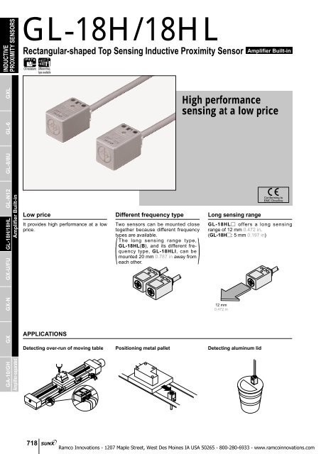
<strong>GL</strong>-<strong>18H</strong>/<strong>18H</strong>L<br />
Rectangular-shaped Top Sensing Inductive Proximity Sensor<br />
Oil resistant<br />
Different freq.<br />
type available<br />
Amplifier Built-in<br />
GXL<br />
High performance<br />
sensing at a low price<br />
GA-10/GH GX GX-N GX-U/FU <strong>GL</strong>-<strong>18H</strong>/<strong>18H</strong>L <strong>GL</strong>-N12<br />
Amplifier-separated Amplifier Built-in<br />
<strong>GL</strong>-8/8U<br />
<strong>GL</strong>-6<br />
Low price<br />
It provides high performance at a low<br />
price.<br />
APPLICATIONS<br />
Different frequency type<br />
Two sensors can be mounted close<br />
together because different frequency<br />
types are available.<br />
The long sensing range type,<br />
<strong>GL</strong>-<strong>18H</strong>L(B), and its different frequency<br />
type, <strong>GL</strong>-<strong>18H</strong>LI, can be<br />
mounted 20 mm 0.787 in away from<br />
each other.<br />
( )<br />
Long sensing range<br />
Detecting over-run of moving table Positioning metal pallet Detecting aluminum lid<br />
Conforming to<br />
EMC Directive<br />
<strong>GL</strong>-<strong>18H</strong>L offers a long sensing<br />
range of 12 mm 0.472 in.<br />
(<strong>GL</strong>-<strong>18H</strong>: 5 mm 0.197 in)<br />
12 mm<br />
0.472 in<br />
718
ORDER GUIDE<br />
Type<br />
Standard<br />
Different<br />
frequency<br />
Long sensing<br />
range<br />
Different<br />
frequency<br />
18<br />
0.709<br />
Appearance<br />
(mm in)<br />
18<br />
0.709<br />
28<br />
1.102<br />
Sensing range (Note) Model No. Output<br />
Maximum operation distance<br />
5 mm 0.197 in<br />
(0 to 4 mm 0 to 0.157 in)<br />
Stable sensing range<br />
12 mm 0.472 in<br />
( )<br />
0 to 10 mm<br />
0 to 0.394 in<br />
<strong>GL</strong>-<strong>18H</strong><br />
<strong>GL</strong>-<strong>18H</strong>I<br />
<strong>GL</strong>-<strong>18H</strong>B<br />
<strong>GL</strong>-<strong>18H</strong>L<br />
<strong>GL</strong>-<strong>18H</strong>LI<br />
<strong>GL</strong>-<strong>18H</strong>LB<br />
NPN<br />
open-collector<br />
transistor<br />
<strong>GL</strong>-<strong>18H</strong>/<strong>18H</strong>L<br />
Output operation<br />
Normally open<br />
Normally closed<br />
Normally open<br />
Normally closed<br />
Note: The maximum operation distance stands for the maximum distance for which the sensor can detect the standard sensing<br />
object.<br />
The stable sensing range stands for the sensing range for which the sensor can stably detect the standard sensing object<br />
even if there is an ambient temperature drift and/or supply voltage fluctuation.<br />
Accessory<br />
• MS-<strong>GL</strong><strong>18H</strong>L<br />
Sensor mounting<br />
bracket<br />
( )<br />
Two M3 (length 25 mm 0.948 in)<br />
pan head screws are attached.<br />
INDUCTIVE<br />
PROXIMITY SENSORS<br />
GXL<br />
<strong>GL</strong>-6<br />
<strong>GL</strong>-8/8U<br />
SPECIFICATIONS<br />
Item<br />
Max. operation distance (Note)<br />
Stable sensing range (Note)<br />
Standard sensing object<br />
Hysteresis<br />
Supply voltage<br />
Current consumption<br />
Output<br />
Type<br />
Model No.<br />
Utilization category<br />
Output operation<br />
Max. response frequency<br />
Operation indicator<br />
Pollution degree<br />
Protection<br />
Ambient temperature<br />
Ambient humidity<br />
EMC<br />
Voltage withstandability<br />
Insulation resistance<br />
Vibration resistance<br />
Shock resistance<br />
Sensing range Temperature characteristics<br />
variation Voltage characteristics<br />
Material<br />
Cable<br />
Cable extension<br />
Weight<br />
Accessory<br />
Environmental resistance<br />
Standard<br />
Long sensing range<br />
Different frequency<br />
Different frequency<br />
<strong>GL</strong>-<strong>18H</strong> <strong>GL</strong>-<strong>18H</strong>I <strong>GL</strong>-<strong>18H</strong>B <strong>GL</strong>-<strong>18H</strong>L <strong>GL</strong>-<strong>18H</strong>LI <strong>GL</strong>-<strong>18H</strong>LB<br />
5 mm 0.197 in10 % 12 mm 0.472 in10 %<br />
0 to 4 mm 0 to 0.157 in 0 to 10 mm 0 to 0.394 in<br />
Iron sheet 2525t 1 mm 0.9840.984t 0.039 in Iron sheet 4040t 1 mm 1.5751.575t 0.039 in<br />
15 % or less of operation distance<br />
10 to 30 V DC Ripple P-P 10 % or less<br />
10 mA or less<br />
NPN open-collector transistor<br />
• Maximum sink current: 100 mA<br />
• Applied voltage: 30 V DC or less (between output and 0 V)<br />
• Residual voltage: 1.5 V or less (at 100 mA sink current)<br />
0.4 V or less (at 16 mA sink current)<br />
DC-12 or DC-13<br />
Normally open Normally closed Normally open Normally closed<br />
1 kHz 500 Hz<br />
Red LED (lights up when the output is ON)<br />
3 (Industrial environment)<br />
IP67 (IEC), IP67g (JEM)<br />
25 to70 C 13 to158 F, Storage:25 to70 C 13 to158 F<br />
45 to 85 % RH, Storage: 45 to 85 % RH<br />
EN 50081-2, EN 50082-2, EN 60947-5-2<br />
1,000 V AC for one min. between all supply terminals connected together and enclosure<br />
50 MΩ, or more, with 250 V DC megger between all supply terminals connected together and enclosure<br />
10 to 55 Hz frequency, 1.5 mm 0.059 in amplitude in X, Y and Z directions for two hours each<br />
1,000 m/s 2 acceleration (100 G approx.) in X, Y and Z directions for three times each<br />
Over ambient temperature range25 to70 C 13 to158 F: within10 % of sensing range at 20 C 68 F<br />
Within2 % for10 % fluctuation of the supply voltage<br />
Enclosure: Polyalylate<br />
0.3 mm 2 3-core oil resistant cabtyre cable, 1 m 3.281 ft long<br />
Extension up to total 100 m 328.084 ft is possible with 0.3 mm 2 , or more, cable.<br />
45 g approx.<br />
MS-<strong>GL</strong><strong>18H</strong>L (Sensor mounting bracket): 1 set<br />
Note: The maximum operation distance stands for the maximum distance for which the sensor can detect the standard sensing object.<br />
The stable sensing range stands for the sensing range for which the sensor can stably detect the standard sensing object even if there is an ambient<br />
temperature drift and/or supply voltage fluctuation.<br />
Amplifier-separated Amplifier Built-in<br />
GA-10/GH GX GX-N GX-U/FU <strong>GL</strong>-<strong>18H</strong>/<strong>18H</strong>L <strong>GL</strong>-N12<br />
719
INDUCTIVE<br />
PROXIMITY SENSORS<br />
<strong>GL</strong>-<strong>18H</strong>/<strong>18H</strong>L<br />
I/O CIRCUIT AND WIRING DIAGRAMS<br />
<strong>GL</strong>-<strong>18H</strong><br />
<strong>GL</strong>-<strong>18H</strong>L<br />
I/O circuit diagram<br />
Wiring diagram<br />
GXL<br />
Sensor circuit<br />
Tr<br />
ZD<br />
Color code<br />
(Brown)V<br />
Load<br />
(Black) Output (Note)<br />
(Blue) 0 V<br />
100 mA max.<br />
<br />
10 to 30 V DC Blue<br />
Brown<br />
Black<br />
Load<br />
<br />
<br />
10 to 30 V DC<br />
<strong>GL</strong>-6<br />
Internal circuit<br />
Users’ circuit<br />
<strong>GL</strong>-8/8U<br />
Note: Please carry out the wiring carefully since protection circuit against<br />
reverse power supply connection is not incorporated.<br />
Note: Further, the output is not incorporated with a short-circuit protection<br />
circuit.<br />
Do not connect it directly to a power supply or a capacitive load.<br />
Symbols ... ZD: Surge absorption zener diode<br />
Tr : NPN output transistor<br />
GA-10/GH GX GX-N GX-U/FU <strong>GL</strong>-<strong>18H</strong>/<strong>18H</strong>L <strong>GL</strong>-N12<br />
Amplifier-separated Amplifier Built-in<br />
SENSING CHARACTERISTICS (TYPICAL)<br />
<strong>GL</strong>-<strong>18H</strong><br />
Sensing field<br />
8<br />
0.315<br />
Setting distance L (mm in)<br />
Setting distance L (mm in)<br />
6<br />
0.236<br />
4<br />
0.157<br />
2<br />
0.079<br />
0<br />
10<br />
0.394<br />
<strong>GL</strong>-<strong>18H</strong>L<br />
Sensing field<br />
10<br />
0.394<br />
5<br />
0.197<br />
0<br />
20<br />
0.787<br />
Standard sensing<br />
object Iron sheet<br />
2525t 1 mm<br />
0.9840.984t 0.039 in<br />
#<br />
5 0 5<br />
0.197<br />
0.197<br />
Left Center Right<br />
Operating point ?(mm in)<br />
10 0 10<br />
0.394<br />
0.394<br />
Left Center Right<br />
Operating point ?(mm in)<br />
L<br />
10<br />
0.394<br />
Standard sensing<br />
object Iron sheet<br />
4040t 1 mm<br />
1.5751.575t 0.039 in<br />
#<br />
L<br />
20<br />
0.787<br />
Correlation between sensing object size and sensing range<br />
8<br />
0.315 Sensing object aa mm aa in<br />
Sensing range L (mm in)<br />
6<br />
0.236<br />
4<br />
0.157<br />
2<br />
0.079<br />
0 10<br />
0.394<br />
20<br />
0.787<br />
30<br />
1.181<br />
Sensing object side<br />
length a (mm in)<br />
15<br />
0.591<br />
10<br />
0.394<br />
5<br />
0197<br />
L<br />
t 1 mm<br />
t 0.039 in<br />
Iron<br />
Stainless steel<br />
(SUS304)<br />
Brass<br />
Aluminum<br />
40<br />
1.575<br />
Correlation between sensing object size and sensing range<br />
20<br />
0.787 Sensing object aa mm aa in<br />
Sensing range L (mm in)<br />
0 20<br />
0.787<br />
40<br />
1.575<br />
60<br />
2.362<br />
Sensing object side<br />
length a (mm in)<br />
L<br />
t 1 mm<br />
t 0.039 in<br />
Iron<br />
Stainless steel<br />
(SUS304)<br />
Brass<br />
Aluminum<br />
80<br />
3.150<br />
As the sensing object size becomes smaller than<br />
the standard size (iron sheet 2525t 1 mm<br />
0.9840.984t 0.039 in), the sensing range<br />
shortens as shown in the left figure.<br />
As the sensing object size becomes smaller than<br />
the standard size (iron sheet 4040t 1 mm<br />
1.5751.575t 0.039 in), the sensing range<br />
shortens as shown in the left figure.<br />
720
PRECAUTIONS FOR PROPER USE<br />
This product is not a safety sensor. Its use is not<br />
intended or designed to protect life and prevent body<br />
injury or property damage from dangerous parts of<br />
machinery. It is a normal object detection sensor.<br />
Mounting<br />
• The tightening torque should<br />
be 0.5 Nm or less.<br />
• To mount the sensor with a<br />
nut, the thru-hole diameter<br />
should be "3.4 mm "0.134 in.<br />
• Screws, nuts or washers<br />
are not supplied. Please<br />
arrange them separately.<br />
10.5 mm<br />
0.413 in<br />
M3 pan head screws or truss<br />
head screw<br />
(Do not uses flat head screws)<br />
M30.5 mm 0.020 in<br />
tapped holes or "3.4 mm<br />
0.134 in thru-holes<br />
One set of two washers<br />
and a nut is used.<br />
<strong>GL</strong>-<strong>18H</strong>/<strong>18H</strong>L<br />
Refer to p.1152l for general precautions.<br />
Sensing range<br />
• The sensing range is specified for the standard sensing<br />
object. With a non-ferrous metal, the sensing range is<br />
obtained by multiplying with the correction coefficient<br />
specified below. Further, the sensing range also changes if<br />
the sensing object is plated.<br />
Correction coefficient<br />
Metal<br />
Iron<br />
Stainless steel<br />
(SUS304)<br />
Brass<br />
Model No.<br />
<strong>GL</strong>-<strong>18H</strong><br />
1<br />
0.68 approx.<br />
0.45 approx.<br />
<strong>GL</strong>-<strong>18H</strong>L<br />
1<br />
0.65 approx.<br />
0.42 approx.<br />
INDUCTIVE<br />
PROXIMITY SENSORS<br />
GXL<br />
<strong>GL</strong>-6<br />
Influence of surrounding metal<br />
• When there is a metal near the sensor, keep the minimum<br />
separation distance specified below.<br />
E<br />
F<br />
Metal<br />
Metal<br />
B<br />
Between ‘I’<br />
type and<br />
non ‘I’ type<br />
A<br />
C<br />
<strong>GL</strong>-<strong>18H</strong><br />
Metal<br />
Metal<br />
Between two ‘I’<br />
types or two<br />
non ‘I’ types<br />
A<br />
B<br />
C<br />
D<br />
Between ‘I’<br />
type and<br />
non ‘I’ type<br />
<strong>GL</strong>-<strong>18H</strong><br />
5 mm 0.197 in<br />
20 mm 0.787 in<br />
0 mm 0.000 in<br />
5 mm 0.197 in<br />
<strong>GL</strong>-<strong>18H</strong>L<br />
Between two ‘I’<br />
types or two<br />
non ‘I’ types<br />
0 mm (Note 2) 40 mm 1.575 in 20 mm 0.787 in 130 mm 5.118 in<br />
20 mm 0.787 in 70 mm 2.756 in 40 mm 1.575 in 200 mm 7.874 in<br />
<strong>GL</strong>-<strong>18H</strong>L<br />
25 mm 0.984 in<br />
60 mm 2.362 in<br />
20 mm 0.787 in (Note)<br />
30 mm 1.181 in<br />
Note: When the <strong>GL</strong>-<strong>18H</strong>L is mounted<br />
on an insulator, or seated on the<br />
D<br />
attached aluminum mounting<br />
D<br />
bracket, the distance ‘C’ can be<br />
zero.<br />
Mutual interference prevention<br />
• When two or more sensors are installed in parallel or face<br />
to face, keep the minimum separation distance specified<br />
below to avoid mutual interference.<br />
Notes: 1) ‘I’ in the model No. specifies the different frequency type.<br />
Notes: 2) Close mounting is possible for up to two sensors.<br />
When mounting three sensors or more, at an equal spacing, in a<br />
row, the minimum value of dimension ‘E’ should be 11 mm 0.433 in.<br />
DIMENSIONS (Unit: mm in)<br />
<strong>GL</strong>-<strong>18H</strong><br />
<strong>GL</strong>-<strong>18H</strong>L<br />
Sensing<br />
direction<br />
18<br />
0.709<br />
18<br />
0.709<br />
Sensor MS-<strong>GL</strong><strong>18H</strong>L Sensor mounting bracket for <strong>GL</strong>-<strong>18H</strong>L (Accessory)<br />
28<br />
1.102<br />
24.5<br />
0.965<br />
18.8<br />
0.740<br />
10.5<br />
0.413<br />
4<br />
0.157<br />
2-"3.3 "0.130<br />
mounting holes<br />
11<br />
0.433<br />
"4.8 "0.189 cable,<br />
1 m 3.281 ft long<br />
Operation indicator (Red)<br />
11<br />
0.433<br />
7<br />
0.276<br />
E<br />
F<br />
Aluminum<br />
2-M30.5 0.020<br />
0.43 approx.<br />
10.5<br />
0.413<br />
4.5<br />
0.177<br />
10<br />
0.394<br />
11<br />
0.433<br />
20<br />
0.787<br />
3.2<br />
0.126<br />
10<br />
0.394<br />
17.5<br />
0.689<br />
(6.1)(0.240)<br />
(4.5)(0.177)<br />
20<br />
0.787<br />
t 2<br />
t 0.079<br />
0.41 approx.<br />
Wiring<br />
• Please carry out the wiring carefully since protection<br />
circuit against reverse power supply connection is not<br />
incorporated.<br />
• Further, the output is not incorporated with a short-circuit<br />
protection circuit. Do not connect it directly to a power<br />
supply or a capacitive load.<br />
Others<br />
• Do not use during the initial transient time (50 ms) after<br />
the power supply is switched on.<br />
The CAD data in the dimensions can be downloaded from the SUNX website: http://www.sunx.co.jp/<br />
Material: Aluminum<br />
Two M3 (length 25 mm 0.984 in)<br />
pan head screws are attached.<br />
721<br />
<strong>GL</strong>-8/8U<br />
Amplifier-separated Amplifier Built-in<br />
GA-10/GH GX GX-N GX-U/FU <strong>GL</strong>-<strong>18H</strong>/<strong>18H</strong>L <strong>GL</strong>-N12