SL-BMW/BW - Ramco Innovations
SL-BMW/BW - Ramco Innovations
SL-BMW/BW - Ramco Innovations

Create successful ePaper yourself
Turn your PDF publications into a flip-book with our unique Google optimized e-Paper software.
1 2 3 4<br />
WIRE-SAVING UNITS<br />
<strong>SL</strong>-<strong>BMW</strong>/<strong>BW</strong><br />
Sensor Block for Simple Wiring<br />
<strong>SL</strong>-<strong>BMW</strong>/<strong>BW</strong> SC<br />
Simple Wiring<br />
Quick connection of<br />
16 sensors<br />
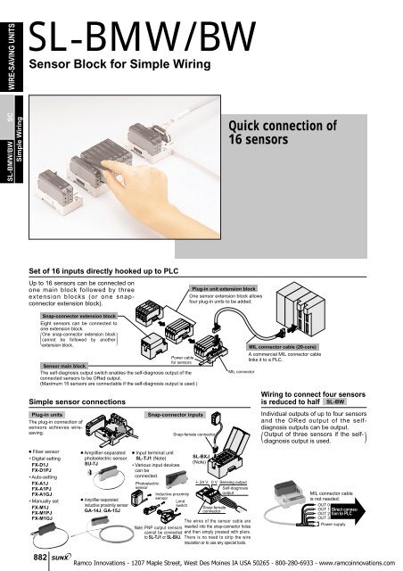
Set of 16 inputs directly hooked up to PLC<br />
Up to 16 sensors can be connected on<br />
one main block followed by three<br />
extension blocks (or one snapconnector<br />
extension block).<br />
Plug-in unit extension block<br />
One sensor extension block allows<br />
four plug-in units to be added.<br />
Snap-connector extension block<br />
Eight sensors can be connected to<br />
one extension block.<br />
One snap-connector extension block<br />
( cannot be followed by another )<br />
extension block.<br />
Power cable<br />
for sensors<br />
Sensor main block<br />
The self-diagnosis output switch enables the self-diagnosis output of the<br />
connected sensors to be ORed output.<br />
(Maximum 15 sensors are connectable if the self-diagnosis output is used.)<br />
Simple sensor connections<br />
Plug-in units<br />
The plug-in connection of<br />
sensors achieves wiresaving.<br />
Snap-connector inputs<br />
Snap-female connector<br />
MIL connector<br />
MIL connector cable (20-core)<br />
A commercial MIL connector cable<br />
links it to a PLC.<br />
Wiring to connect four sensors<br />
is reduced to half <strong>SL</strong>-<strong>BW</strong><br />
Individual outputs of up to four sensors<br />
and the ORed output of the selfdiagnosis<br />
outputs can be output.<br />
Output of three sensors if the selfdiagnosis<br />
output is used.<br />
( )<br />
● Fiber sensor<br />
• Digital setting<br />
FX-D1J<br />
FX-D1PJ<br />
• Auto-setting<br />
FX-A1J<br />
FX-A1PJ<br />
FX-A1GJ<br />
• Manually set<br />
FX-M1J<br />
FX-M1PJ<br />
FX-M1GJ<br />
882<br />
● Amplifier-separated<br />
photoelectric sensor<br />
SU-7J<br />
● Amplifier-separated<br />
inductive proximity sensor<br />
GA-14J, GA-15J<br />
● Input terminal unit<br />
<strong>SL</strong>-TJ1 (Note)<br />
• Various input devices<br />
can be<br />
connected.<br />
Photoelectric<br />
sensor<br />
Inductive proximity<br />
sensor<br />
Limit<br />
switch<br />
<strong>SL</strong>-BXJ<br />
(Note)<br />
24 V<br />
0 V Sensing output<br />
Self-diagnosis<br />
output<br />
Snap-female<br />
connector<br />
The wires of the sensor cable are<br />
Note: PNP output sensors inserted into the snap-connector holes<br />
cannot be connected and then simply pressed with pliers.<br />
to <strong>SL</strong>-TJ1 or <strong>SL</strong>-BXJ. There is no need to strip the wire<br />
insulation or to use any special tools.<br />
MIL connector cable<br />
is not needed.<br />
OUT 0<br />
OUT 1 Direct connection<br />
to PLC<br />
OUT 2<br />
OUT 3<br />
Power supply
APPLICATIONS<br />
Wire-saving in sensor connection (Detecting presence of tablets)<br />
In the past<br />
Now, using <strong>SL</strong>-<strong>BMW</strong><br />
FD-G4<br />
<strong>SL</strong>-<strong>BMW</strong>/<strong>BW</strong><br />
FD-G4<br />
WIRE-SAVING UNITS<br />
FX-MR2<br />
FX-MR2<br />
To PLC or intermediate terminal block<br />
<strong>SL</strong>-<strong>BMW</strong><br />
MIL connector cable<br />
to PLC<br />
FX-D1J<br />
<strong>SL</strong>-BX<br />
Simple Wiring<br />
<strong>SL</strong>-<strong>BMW</strong>/<strong>BW</strong> SC<br />
ORDER GUIDE<br />
Designation Appearance Model No. Description<br />
Plug-in unit<br />
sensor main block<br />
<strong>SL</strong>-<strong>BMW</strong><br />
One sensor main block allows four plug-in units to be connected, and if<br />
three extension blocks are used, total 16 plug-in units can be connected.<br />
A commercial MIL connector cable links it to a PLC input module.<br />
The ORed output of the self-diagnosis outputs of the connected sensors<br />
(<br />
can be output as Channel 0. However, in this case, a plug-in unit cannot<br />
)<br />
be connected at Channel 0.<br />
Sensor block<br />
Plug-in unit<br />
extension block<br />
Snap-connector<br />
extension block<br />
(Note)<br />
<strong>SL</strong>-BX<br />
<strong>SL</strong>-BXJ<br />
Four plug-in units can be connected to one extension block.<br />
Eight input devices can be connected to one extension block.<br />
The connections are simple using snap-female connectors.<br />
Plug-in unit<br />
4-channel sensor<br />
block<br />
<strong>SL</strong>-<strong>BW</strong><br />
Four plug-in units can be connected to one extension block.<br />
The attached cable links it to a PLC input module.<br />
The ORed output of the self-diagnosis outputs of the connected sensors<br />
can be output as Channel 0. However, in this case, a plug-in unit cannot<br />
be connected at Channel 0.<br />
( )<br />
Note: PNP output device cannot be connected.<br />
883
WIRE-SAVING UNITS<br />
<strong>SL</strong>-<strong>BMW</strong>/<strong>BW</strong><br />
ORDER GUIDE<br />
Designation Appearance Model No. Description<br />
<strong>SL</strong>-<strong>BMW</strong>/<strong>BW</strong> SC<br />
Simple Wiring<br />
Plug-in unit<br />
Digital setting<br />
fiber sensor<br />
Auto-setting<br />
fiber sensor<br />
Manually set<br />
fiber sensor<br />
FX-D1J<br />
FX-D1PJ<br />
FX-A1J<br />
FX-A1PJ<br />
FX-A1GJ<br />
FX-M1J<br />
FX-M1PJ<br />
FX-M1GJ<br />
NPN type<br />
(Red LED)<br />
PNP type<br />
(Red LED)<br />
NPN type<br />
(Red LED)<br />
PNP type<br />
(Red LED)<br />
NPN type<br />
(Green LED)<br />
NPN type<br />
(Red LED)<br />
PNP type<br />
(Red LED)<br />
NPN type<br />
(Green LED)<br />
Its thickness is merely 10 mm 0.394 in. The incident light<br />
intensity and the threshold value can be seen at a glance<br />
from the backlight LCD. Further, threshold value setting is<br />
simple by using the jog switch.<br />
(Please contact our office for details.)<br />
Its thickness is merely 10 mm 0.394 in. The sensitivity<br />
setting is simple by using the jog switch. Level indicators,<br />
comprising of 10 LEDs, which enable confirmation of the<br />
set sensitivity at a glance, have been incorporated.<br />
(Please contact our office for details.)<br />
Its thickness is merely 10 mm 0.394 in. Since the<br />
sensitivity setting is done by a 12-turn potentiometer, fine<br />
setting is possible.<br />
(Please contact our office for details.)<br />
Amplifier-separated<br />
photoelectric<br />
sensor<br />
SU-7J<br />
Its thickness is merely 10 mm 0.394 in. The sensitivity is automatically set<br />
with ease. 12 kinds of sensor heads are suitable with it.<br />
(For details, refer to p.386 l for the SU-7 series.)<br />
Amplifierseparated<br />
inductive<br />
proximity<br />
sensor<br />
One-touch<br />
clamping type<br />
Screw<br />
tightening<br />
type<br />
GA-14J<br />
GA-15J<br />
Its thickness is merely 10 mm 0.394 in. The sensitivity is so precisely set<br />
with the 18-turn adjuster that the sensor is suitable for sophisticated<br />
applications with a high repeatability of 1!m or less.<br />
(For details, refer to p.754 l for the GA-10 series.)<br />
Input terminal unit<br />
(Note)<br />
<strong>SL</strong>-TJ1<br />
It allows connection of 1 No. of various kinds of input devices, such as, a<br />
photoelectric sensor, an inductive proximity sensor or a limit switch.<br />
Snap-female<br />
connector<br />
1 2 3 4<br />
<strong>SL</strong>-CJ1<br />
(White)<br />
<strong>SL</strong>-CJ2<br />
(Black)<br />
For 0.08 to 0.2 mm 2 (conductor cross-section area)<br />
Wire dia.: "0.7 to "1.2 mm "0.028 to "0.047 in<br />
For 0.3 mm 2 (conductor cross-section area)<br />
Wire dia.: "1.1 to "1.6 mm "0.043 to "0.063 in<br />
It is used to connect an input device<br />
to the snap-connector extension<br />
block. When hook-up wiring, make<br />
sure to use the <strong>SL</strong>-JPC exclusive<br />
pliers.<br />
Note: PNP output device cannot be connected.<br />
SPECIFICATIONS<br />
Sensor blocks<br />
Item<br />
Supply voltage<br />
Designation Plug-in unit sensor main block Plug-in unit extension block Snap-connector extension block<br />
Model No.<br />
Plug-in unit 4-channel sensor block<br />
<strong>SL</strong>-<strong>BMW</strong> <strong>SL</strong>-BX <strong>SL</strong>-BXJ (Note 1) <strong>SL</strong>-<strong>BW</strong><br />
Depends on used input<br />
device<br />
Supplied from sensor main<br />
block<br />
Depends on used input<br />
device<br />
Current consumption<br />
Input channel No.<br />
Ambient temperature<br />
Ambient humidity<br />
Material<br />
Cable<br />
Weight<br />
Accessories<br />
Depends on the number and characteristics of the connected<br />
input devices (Note 2)<br />
0.3 mm 2 2-core cabtyre cable, 2 m 6.562 ft long<br />
4 inputs (Max. 16 inputs with extension blocks) (Note 3) 4 inputs (Note 4)<br />
0 to55 C 32 to131F (No dew condensation), Storage:20 to70C 4 to158F<br />
35 to 85 % RH, Storage: 35 to 85 % RH<br />
Enclosure: Heat-resistant ABS, Connector: PBT, Cover (<strong>SL</strong>-BXJ only): Polycarbonate<br />
130 g approx. 30 g approx. 60 g approx. 130 g approx.<br />
Extension connector cap: 1 pc.<br />
Plug-in connector cap: 1 set (Note 5)<br />
6 mA or less / channel<br />
excluding connected users’<br />
devices<br />
( )<br />
Input designation label set: 1 sheet<br />
Socket seal: 8 sheets<br />
Depends on the number and<br />
characteristics of the connected<br />
input devices (Note 2)<br />
0.2 mm 2 6-core cabtyre cable, 2 m 6.562 ft long<br />
Plug-in connector cap: 1 set<br />
(Note 5)<br />
Notes: 1) PNP output device cannot be connected.<br />
Notes: 2) Neither <strong>SL</strong>-<strong>BMW</strong>, <strong>SL</strong>-BX or <strong>SL</strong>-<strong>BW</strong> consumes current by itself.<br />
Notes: 3) Maximum 15 inputs are allowed if the self-diagnosis output is used.<br />
Notes: 4) Maximum 3 inputs are allowed if the self-diagnosis output is used.<br />
Notes: 5) Use the extension connector cap and the plug-in connector cap to cover each<br />
exposed connector. Three plug-in connector caps are joined together. If two, or<br />
less, are to be used, cut to separate them.<br />
Extension connector cap<br />
Plug-in connector cap<br />
884
SPECIFICATIONS<br />
Plug-in units<br />
Item<br />
Supply voltage<br />
Current consumption<br />
Output<br />
Applicable fibers<br />
Sensing range<br />
Functions<br />
Connecting method<br />
Ambient temperature<br />
Ambient humidity<br />
Material<br />
Weight<br />
Accessories<br />
Item<br />
Supply voltage<br />
Current consumption<br />
Output<br />
Applicable sensor heads<br />
Sensing range<br />
Functions<br />
Connecting method<br />
Ambient temperature<br />
Ambient humidity<br />
Material<br />
Weight<br />
Accessories<br />
Designation<br />
Model No.<br />
Designation<br />
Model No.<br />
Digital setting fiber sensor Auto-setting fiber sensor Manually set fiber sensor<br />
Red LED type Red LED type Green LED type Red LED type Green LED type<br />
NPN output PNP output NPN output PNP output NPN output NPN output PNP output NPN output<br />
FX-D1J FX-D1PJ FX-A1J FX-A1PJ FX-A1GJ FX-M1J FX-M1PJ FX-M1GJ<br />
12 to 24V DC10 % (24 V DC supplied from sensor block)<br />
45 mA or less 50 mA or less 45 mA or less<br />
Output 1 and Output 2 (Note 1)<br />
Sensing output and self-diagnosis output<br />
FT-B8, FD-B8, etc.<br />
<br />
Red LED type with FT-B8: 650 mm 25.591 in<br />
Green LED type with FT-B8: 115 mm 4.528 in<br />
<br />
Red LED type with FD-B8: 210 mm 8.268 in<br />
Green LED type with FD-B8: 40 mm 1.575 in<br />
ON / OFF-delay timer function<br />
(Note 2)<br />
Interference prevention<br />
function<br />
0 to50 °C 32 to122 °F,<br />
Storage:20 to70 °C 4 to158 °F<br />
Amplifier-separated inductive<br />
Amplifier-separated photoelectric sensor proximity sensor<br />
Input terminal unit<br />
One-touch clamping type Screw tightening type<br />
SU-7J GA-14J GA-15J <strong>SL</strong>-TJ1<br />
12 to 24 V DC10 % (24 V DC supplied from sensor block) 24 V DC10 % (24 V DC supplied from sensor block)<br />
35 mA or less 25 mA or less<br />
Sensing output and self-diagnosis output<br />
SH series<br />
Thru-beam type: 2 m 6.562 ft with SH-33R<br />
Reflective type: 100 mm 3.937 in with SH-32R<br />
Automatic sensitivity setting<br />
Sensitivity shift<br />
Stability margin indication<br />
Interference prevention<br />
0 to 5 sec. variable ON and OFF-delay timers<br />
Connector<br />
Sensing output and disconnection alarm output<br />
GH series<br />
10 to55 °C 14 to131 °F (Note 2), Storage:20 to70 °C4 to158 °F 10 to60 °C 14 to140 °F (Note 2), Storage:20 to70 °C4 to158 °F 10 to50 °C 14 to122 °F (Note 2), Storage:20 to70 °C4 to158 °F<br />
35 to 85 % RH, Storage: 35 to 85% RH<br />
Enclosure: Heat-resistant ABS, Cover: Polycarbonate, Cable lock lever: PPS<br />
65 g approx.<br />
Enclosure: Heat-resistant ABS<br />
Cover: Polycarbonate<br />
20 g approx.<br />
MS-DIN-2 (Amplifier mounting bracket): 1 pc.<br />
Mode indication label: 1 sheet<br />
Connector<br />
35 to 85 % RH, Storage: 35 to 85 % RH<br />
Enclosure: Heat-resistant ABS, Cover: Polycarbonate, Fiber lock lever: PES<br />
70 g approx.<br />
MS-DIN-2 (Amplifier mounting bracket): 1 pc.<br />
Approx. 40 ms fixed OFF-delay timer function<br />
Interference prevention function<br />
10 to50 °C 14 to122 °F (Note 3), Storage:20 to70 °C 4 to158 °F<br />
Notes: 1) Output 2 cannot be used when it is connected to plug-in unit sensor block.<br />
Notes: 2) The timer period of the ON-delay timer and the OFF-delay timer can be selected from 40 ms, 100 ms, 200 ms and 500 ms.<br />
Notes: 3) Please take care that the rated ambient temperature of the sensor block is 0 to55 C 32 to122 F.<br />
Plug-in units<br />
0 mA<br />
7.5 mA or less when the indicator lights<br />
( up, excluding connected users’ device )<br />
NPN output transistor, DC 2-wire type or<br />
relay output sensor, switch, etc.<br />
Signal conditions depend on the input<br />
conditions of the PLC connected to<br />
(<br />
)<br />
the sensor block.<br />
Maximum operating distance (Note 1)<br />
1.2 mm 0.047 in with GH-2S<br />
1.8 mm 0.071 in with GH-3S<br />
2.4 mm 0.094 in with GH-5S<br />
4.0 mm 0.157 in with GH-8S, GH-F8S<br />
Indicators<br />
Disconnection alarm indicator Red LED: lights up when the sensor<br />
Orange LED lights up when the<br />
( input is ON<br />
disconnection alarm output is ON ) ( Yellow LED: lights up when the selfdiagnosis<br />
input is<br />
)<br />
ON<br />
MS-DIN-2 (Amplifier mounting bracket): 1 pc.<br />
Adjusting screwdriver: 1 pc.<br />
<strong>SL</strong>-<strong>BMW</strong>/<strong>BW</strong><br />
MS-DIN-2 (Amplifier mounting bracket): 1 pc.<br />
Adjusting screwdriver: 1 pc.<br />
Connector<br />
Screw-on-terminal connection of<br />
( users’ input device )<br />
Notes: 1) The maximum operating distance represents the maximum distance for which the sensor can detect the standard sensing object at 20 C 68 F<br />
constant ambient temperature.<br />
Notes: 2) Please take care that the rated ambient temperature of the sensor block is 0 to55C 32 to131 F.<br />
WIRE-SAVING UNITS<br />
Simple Wiring<br />
<strong>SL</strong>-<strong>BMW</strong>/<strong>BW</strong> SC<br />
885
WIRE-SAVING UNITS<br />
<strong>SL</strong>-<strong>BMW</strong>/<strong>BW</strong><br />
I/O CIRCUIT AND WIRING DIAGRAMS<br />
<strong>SL</strong>-<strong>BMW</strong><br />
I/O circuit diagram<br />
MIL connector pin position<br />
<strong>SL</strong>-<strong>BMW</strong>/<strong>BW</strong> SC<br />
Simple Wiring<br />
24 V DC<br />
10 %<br />
Self-diagnosis<br />
output<br />
(STB.OUT) / OUT0<br />
OUT1<br />
OUT2<br />
OUT3<br />
OUT4<br />
OUT5<br />
OUT6<br />
OUT7<br />
24 V<br />
0 V<br />
Color code<br />
<br />
<br />
V (Brown)<br />
OUT8<br />
OUT9<br />
OUT10<br />
OUT11<br />
OUT12<br />
OUT13<br />
OUT14<br />
OUT15<br />
24 V<br />
0 V<br />
0 V (Blue)<br />
MIL connector<br />
IN0<br />
STB.IN<br />
Plug-in connector<br />
IN1<br />
STB.IN<br />
IN2<br />
STB.IN<br />
IN3<br />
STB.IN<br />
Extension<br />
connector<br />
24 V<br />
0 V<br />
STB.IN<br />
N.C.<br />
IN4<br />
IN5<br />
IN6<br />
IN7<br />
IN8<br />
IN9<br />
IN10<br />
IN11<br />
IN12<br />
IN13<br />
IN14<br />
IN15<br />
OUT0<br />
OUT1<br />
OUT7<br />
24 V<br />
0 V<br />
OUT8<br />
OUT9<br />
Connector pin position<br />
(TOP VIEW)<br />
OUT15<br />
24 V<br />
0 V<br />
No. 20<br />
pin mark<br />
20 pin MIL connector<br />
Extension connector pin position<br />
Plug-in connector pin position<br />
N.C.<br />
IN7 IN5 (Not connected) 0 V<br />
IN6 IN4 STB.IN 24 V<br />
24 V<br />
0 V<br />
Sensing input (IN)<br />
Self-diagnosis input<br />
(STB. IN)<br />
IN15 IN13 IN11 IN9<br />
IN14 IN12 IN10 IN8<br />
<strong>SL</strong>-<strong>BW</strong><br />
I/O circuit diagram<br />
Color code<br />
V (Brown)<br />
Plug-in connector<br />
24 V DC<br />
10%<br />
<br />
<br />
0 V (Blue)<br />
Self-diagnosis output<br />
(STB.OUT) / OUT0 (Black)<br />
OUT1 (White)<br />
OUT2 (Gray)<br />
OUT3 (Black / White)<br />
IN0<br />
STB.IN<br />
IN1<br />
STB.IN<br />
IN2<br />
STB.IN<br />
IN3<br />
STB.IN<br />
886
ALM.<br />
ALM.<br />
PRECAUTIONS FOR PROPER USE<br />
Mounting<br />
Sensor block<br />
This product does not possess control functions<br />
needed for accident prevention or safety<br />
maintenance.<br />
<br />
1 The front portion of the part<br />
to be mounted is fitted on<br />
the 35 mm 1.378 in width<br />
DIN rail.<br />
2 The rear portion of the part<br />
is then press-fit.<br />
m The sensor block can be<br />
removed by inserting a<br />
‘minus’ screwdriver in the<br />
DIN rail stopper groove and<br />
pulling outwards.<br />
<br />
• In case of mounting with screws, use M4 pan head screws.<br />
And the tightening torque should be 1.2 Nm or less.<br />
1<br />
2<br />
Stopper<br />
35 mm 1.378 in<br />
width DIN rail<br />
‘Minus’<br />
screwdriver<br />
Stopper<br />
<strong>SL</strong>-<strong>BMW</strong>/<strong>BW</strong><br />
Self-diagnosis output (STB.OUT) (<strong>SL</strong>-<strong>BMW</strong> and <strong>SL</strong>-<strong>BW</strong>)<br />
• If the self-diagnosis output switch is<br />
set to the OFF (unmarked) side, all<br />
channels become effective and the<br />
sensing output state (ON or OFF) of<br />
the sensor of each channel is output.<br />
The self-diagnosis output of the<br />
sensor of each channel becomes<br />
ineffective.<br />
• If the self-diagnosis output switch is<br />
set to the ‘ALM.’ side, Channel 1 to<br />
Channel 15 (max.) become effective<br />
[Channel 1 to Channel 3 (max.) for<br />
<strong>SL</strong>-<strong>BW</strong>], and the sensing output<br />
state (ON or OFF) of the sensor of<br />
each channel is output.<br />
The self-diagnosis outputs of the<br />
sensors connected at Channel 1 to<br />
Channel 15 (max.) [Channel 1 to<br />
Channel 3 (max.) for <strong>SL</strong>-<strong>BW</strong>] are<br />
ORed and output from Channel 0.<br />
A sensor cannot be connected at<br />
Channel 0.<br />
WIRE-SAVING UNITS<br />
Simple Wiring<br />
<strong>SL</strong>-<strong>BMW</strong>/<strong>BW</strong> SC<br />
Plug-in unit<br />
1 The groove of the plug-in<br />
unit is fitted on the convex<br />
portion of <strong>SL</strong>-<strong>BMW</strong> or<br />
<strong>SL</strong>-<strong>BW</strong>.<br />
2 The plug-in unit is then<br />
pushed in the direction of<br />
the arrow till a click is felt.<br />
3 Please ensure to fit plug-in<br />
connector caps (attached<br />
with sensor main block) at<br />
places where plug-in units<br />
are not fitted.<br />
Groove<br />
Convex portion<br />
1<br />
Button for plug-in<br />
unit removal<br />
2<br />
Plug-in unit<br />
[16 units max. (<strong>SL</strong>-<strong>BW</strong>: 4 units max.)]<br />
Channel 15<br />
Channel 1<br />
Channel 0<br />
m To dismantle, pull out the plug-in unit while pressing the<br />
button for plug-in unit removal.<br />
Wiring<br />
• Make sure that the power supply is off while wiring.<br />
• Verify that the supply voltage variation is within the rating.<br />
• If power is supplied from a commercial switching<br />
regulator, ensure that the frame ground (F.G.) terminal<br />
of the power supply is connected to an actual ground.<br />
• In case noise generating equipment (switching regulator,<br />
inverter motor, etc.) is used in the vicinity of the sensor<br />
block, connect the frame ground (F.G.) terminal of the<br />
equipment to an actual ground.<br />
• Do not run the wires together with high voltage lines or<br />
power lines or put them in the same raceway. This can<br />
cause malfunction due to induction.<br />
Others<br />
• Do not use during the initial transient time (0.5 sec.) after<br />
the power supply is switched on.<br />
• Avoid dust, dirt, and steam.<br />
• Take care that the sensor does not come in direct contact<br />
with water, oil, grease, or organic solvents, such as,<br />
thinner etc.<br />
887
ALM.<br />
ALM.<br />
ALM.<br />
WIRE-SAVING UNITS<br />
<strong>SL</strong>-<strong>BMW</strong>/<strong>BW</strong> SC<br />
Simple Wiring<br />
<strong>SL</strong>-<strong>BMW</strong>/<strong>BW</strong><br />
PRECAUTIONS FOR PROPER USE<br />
Extension block connection to <strong>SL</strong>-<strong>BMW</strong><br />
• Connection of <strong>SL</strong>-<strong>BMW</strong> to the optional extension block is<br />
done by the extension connector at the side.<br />
Notes: 1) Before the extension, remove the extension connector cap from<br />
<strong>SL</strong>-<strong>BMW</strong>.<br />
Notes: 2) After the extension, make sure to fit the extension connector cap on<br />
the connector of the outer last <strong>SL</strong>-BX. (Not required for <strong>SL</strong>-BXJ)<br />
Plug-in unit<br />
Extension connector<br />
Extension block<br />
<strong>SL</strong>-<strong>BMW</strong><br />
• Maximum three <strong>SL</strong>-BXs can be connected to one <strong>SL</strong>-<strong>BMW</strong>.<br />
Extension<br />
connector cap<br />
Max. 3 units.<br />
Outer last<br />
<strong>SL</strong>-BX<br />
<strong>SL</strong>-BX<br />
<strong>SL</strong>-BX<br />
<strong>SL</strong>-<strong>BMW</strong><br />
• If <strong>SL</strong>-BXJ is connected, one <strong>SL</strong>-BX can still be connected.<br />
However, this <strong>SL</strong>-BX must be connected between<br />
<strong>SL</strong>-<strong>BMW</strong> and <strong>SL</strong>-BXJ.<br />
DIMENSIONS (Unit: mm in)<br />
<strong>SL</strong>-BXJ <strong>SL</strong>-BX <strong>SL</strong>-<strong>BMW</strong><br />
The CAD data in the dimensions can be downloaded from the SUNX website: http://www.sunx.co.jp/<br />
888<br />
<strong>SL</strong>-<strong>BMW</strong><br />
<strong>SL</strong>-<strong>BW</strong><br />
MIL connector (Note 1)<br />
4-plug-in unit<br />
removal buttons<br />
2-"4.5"0.177<br />
mounting holes<br />
1.2<br />
0.047<br />
9.5<br />
0.374<br />
53 2.087<br />
73 2.874<br />
44.7<br />
1.760<br />
11 8.8<br />
0.433 0.346<br />
4 0.157<br />
2 0.079<br />
Connector cap (Note 2)<br />
7.7<br />
39 35<br />
0.303<br />
1.535 1.378 18<br />
0.709<br />
Extension<br />
connector (Note 1)<br />
Notes: 1) Not incorporated on <strong>SL</strong>-<strong>BW</strong>.<br />
Notes: 2) Do not remove it from <strong>SL</strong>-<strong>BW</strong>.<br />
<strong>SL</strong>-BXJ<br />
Extension<br />
connector<br />
2-"4.5 "0.177<br />
mounting holes<br />
4 0.157<br />
19.5<br />
0.768<br />
8-operation<br />
indicators<br />
(Green)<br />
8-connectors<br />
49.5<br />
1.949<br />
Plug-in unit sensor main block<br />
Plug-in unit 4-channel sensor block<br />
Self-diagnosis output switch<br />
"5.8 "0.228 cable, 2m 6.562 ft long<br />
6.6 0.260<br />
11<br />
0.433<br />
20.8<br />
0.819<br />
5.15<br />
0.203<br />
Suitable for 35 mm 1.378 in<br />
width DIN rail<br />
31<br />
1.220 62<br />
20<br />
2.441<br />
0.787<br />
42<br />
1.654<br />
10.3<br />
0.406<br />
Snap-connector extension block<br />
73 2.874<br />
65 2.559<br />
19.8 26.6<br />
0.780 1.047<br />
4<br />
0.157<br />
4.5<br />
0.177<br />
13.6<br />
0.535<br />
21 45<br />
0.827 1.772<br />
12.7<br />
14.4<br />
0.500<br />
0.567<br />
66 2.598<br />
68 2.677<br />
Removable cover<br />
20.2<br />
0.795<br />
36<br />
1.417<br />
Suitable for 35 mm 1.378 in width DIN rail<br />
30.9<br />
1.217<br />
13.8<br />
0.543<br />
14<br />
0.551<br />
6.3 0.248<br />
6.5 0.256<br />
<strong>SL</strong>-BX<br />
Extension connector<br />
4-plug-in unit<br />
removal buttons<br />
2-"4.5 "0.177<br />
mounting holes<br />
10<br />
0.394<br />
Beam-emitting<br />
part<br />
Beam-receiving<br />
part<br />
1.2<br />
0.047<br />
35<br />
1.378<br />
FX-D1J<br />
FX-D1PJ<br />
Plug-in unit extension block<br />
19.8<br />
0.780<br />
53<br />
2.087<br />
73<br />
2.874<br />
Output 1 operation<br />
indicator (Orange)<br />
1.8 0.2<br />
0.071 0.008<br />
12.3<br />
0.484<br />
Output 2 operation<br />
indicator (Orange) (Note 2)<br />
7.5<br />
0.295<br />
31.5<br />
1.240<br />
7.5<br />
0.295<br />
4<br />
0.157<br />
26.6<br />
1.047<br />
4.5<br />
10.5 0.177<br />
0.413<br />
20 41.5<br />
0.787 1.634<br />
4<br />
0.157<br />
18<br />
0.709<br />
5.3<br />
0.209<br />
Extension connector<br />
Suitable for 35 mm 1.378 in<br />
width DIN rail<br />
3<br />
0.118<br />
Plug-in unit (Fiber sensor)<br />
11.1<br />
0.437<br />
4 digit LCD<br />
(with backlight)<br />
14.7<br />
0.579<br />
22<br />
0.866<br />
59<br />
2.323<br />
36.5<br />
1.437<br />
Jog switch<br />
1.2<br />
0.047<br />
30.9<br />
1.217<br />
10.3<br />
0.406<br />
2.1 0.083<br />
Mode selection switch<br />
8.2<br />
0.323<br />
3.2<br />
0.126<br />
7.2<br />
0.283<br />
12.2<br />
0.480<br />
6.2 5<br />
0.244 0.197<br />
Suitable for 35 mm 1.378 in<br />
width DIN rai<br />
14<br />
0.551<br />
9<br />
0.354<br />
Notes: 1) The top view is shown without the cover.<br />
Notes: 2) Output 2 cannot be used when it is connected to plug-in unit<br />
sensor block.
DIMENSIONS (Unit: mm in)<br />
FX-A1J FX-A1GJ<br />
FX-A1PJ<br />
10<br />
0.394<br />
Beam-emitting<br />
part<br />
Beam-receiving<br />
part<br />
Stability indicator (Green)<br />
Operation indicator (Orange)<br />
0.2<br />
0.008<br />
1.45<br />
0.057<br />
7.5<br />
0.295<br />
31.5<br />
1.240<br />
7.5<br />
0.295<br />
4<br />
0.157<br />
3<br />
0.118<br />
Plug-in unit (Fiber sensor)<br />
12.3<br />
0.484<br />
2.4<br />
0.094<br />
11.1<br />
0.437<br />
2<br />
0.079<br />
2.8<br />
0.110<br />
18<br />
0.709<br />
59<br />
2.323<br />
36.5<br />
1.437<br />
Note: The top view is shown without the cover.<br />
<strong>SL</strong>-<strong>BMW</strong>/<strong>BW</strong><br />
The CAD data in the dimensions can be downloaded from the SUNX website: http://www.sunx.co.jp/<br />
Level indicators (Green)<br />
Jog switch<br />
1.2<br />
0.047<br />
13.5<br />
0.531<br />
2.1<br />
0.083<br />
Mode selection switch<br />
8.2<br />
0.323<br />
3.2<br />
0.126<br />
7.2<br />
0.283<br />
12.2<br />
0.480<br />
6.2 5<br />
0.244 0.197<br />
Suitable for 35 mm 1.378 in<br />
width DIN rail<br />
9<br />
0.354<br />
FX-M1J FX-M1GJ<br />
FX-M1PJ<br />
Operation mode switch<br />
Stability indicator (Green)<br />
Operation indicator (Orange)<br />
0.2<br />
0.008<br />
10<br />
0.394<br />
Beam-emitting<br />
part<br />
Beam-receiving<br />
part<br />
0.7<br />
0.028<br />
2.1<br />
0.083<br />
7.5<br />
0.295<br />
31.5<br />
1.240<br />
7.5<br />
0.295<br />
4<br />
0.157<br />
3<br />
0.118<br />
Plug-in unit (Fiber sensor)<br />
12.3 2.8<br />
0.110<br />
6 7 11.25<br />
0.236 0.276 0.443<br />
59<br />
2.323<br />
0.484<br />
3.9<br />
0.154<br />
11.1<br />
0.437<br />
36.5<br />
1.437<br />
Note: The top view is shown without the cover.<br />
Timer operation selection switch<br />
Frequency selection switch<br />
Sensitivity level indicator<br />
Sensitivity adjuster<br />
1.4<br />
0.055<br />
7.75<br />
0.305<br />
8.2<br />
0.323<br />
3.2<br />
0.126<br />
7.2<br />
0.283<br />
12.2<br />
0.480<br />
6.2 5<br />
0.244 0.197<br />
Suitable for 35 mm 1.378 in<br />
width DIN rail<br />
9<br />
0.354<br />
WIRE-SAVING UNITS<br />
Simple Wiring<br />
<strong>SL</strong>-<strong>BMW</strong>/<strong>BW</strong> SC<br />
10<br />
0.394<br />
5.8<br />
0.228<br />
24.3<br />
0.957<br />
SU-7J<br />
Setting mode selection switch<br />
Cable lock lever<br />
Beam-receiving cable inlet<br />
Beam-emitting cable inlet<br />
5<br />
0.197<br />
5.5<br />
0.217<br />
2<br />
0.079<br />
31.5 2.1<br />
1.240 0.083<br />
3<br />
0.118<br />
Plug-in unit<br />
(Amplifier-separated photoelectric sensor)<br />
GY<br />
BK<br />
23<br />
0.906<br />
8<br />
0.315<br />
19.1<br />
0.752<br />
Timer adjuster<br />
Sensitivity setting buttons<br />
Stability indicator (Green)<br />
4.2 5 3.5<br />
0.165 0.197 0.138<br />
6.2<br />
0.244<br />
11.4 8.9 9 6.3<br />
0.449 0.350 0.354 0.248<br />
67<br />
2.638<br />
36.5<br />
1.437<br />
5.6 0.220<br />
Operation indicator (Red)<br />
3.1<br />
0.122<br />
8.2<br />
0.323<br />
3<br />
0.118<br />
7.2<br />
0.283<br />
12.2<br />
0.480<br />
6.2 5<br />
0.244 0.197<br />
Suitable for 35 mm 1.378 in<br />
width DIN rail<br />
Note: The top view is shown without the cable and the cover.<br />
9<br />
0.354<br />
10<br />
0.394<br />
5.8<br />
0.228<br />
24.3<br />
0.957<br />
GA-14J<br />
Cable core<br />
inlet<br />
Shield wire inlet<br />
5<br />
0.197<br />
3.8<br />
0.150<br />
2<br />
0.079<br />
31.5 2<br />
1.240 0.079<br />
3<br />
0.118<br />
Plug-in unit<br />
(Amplifier-separated inductive proximity sensor)<br />
Cable lock lever<br />
4.2 3.2<br />
9.1 0.165 0.126<br />
0.358<br />
23 20.4<br />
0.906 0.803<br />
67<br />
2.638<br />
8<br />
0.315<br />
19<br />
0.748<br />
36.5<br />
1.437<br />
Operation mode switch<br />
Sensitivity adjuster<br />
Operation indicator (Red)<br />
15.3<br />
0.602<br />
5.6 0.220<br />
Disconnection alarm<br />
indicator (Orange)<br />
3<br />
0.118<br />
8.2<br />
0.323<br />
3<br />
0.118<br />
7.2<br />
0.283<br />
12.2<br />
0.480<br />
6.2<br />
0.244<br />
Suitable for 35 mm 1.378 in<br />
width DIN rail<br />
Note: The top view is shown without the cable and the cover.<br />
9<br />
0.354<br />
5<br />
0.197<br />
GA-15J<br />
Screw for cable clamp<br />
5<br />
0.197<br />
Plug-in unit<br />
(Amplifier-separated inductive proximity sensor)<br />
Operation mode switch<br />
Sensitivity adjuster<br />
Operation indicator (Red)<br />
<strong>SL</strong>-TJ1<br />
24 V<br />
ALM-IN<br />
Plug-in unit (Input terminal unit)<br />
0 V<br />
IN<br />
Self-diagnosis<br />
input indicator (Yellow)<br />
10<br />
0.394<br />
2.5<br />
0.098<br />
Shield wire<br />
inlet<br />
12.7<br />
0.500<br />
Cable core<br />
inlet<br />
31.5<br />
0.531<br />
3<br />
0.118<br />
4.2<br />
0.165<br />
10 13<br />
0.394 0.512<br />
19<br />
0.748<br />
8<br />
0.315<br />
3.2<br />
0.126<br />
20.4<br />
0.803<br />
67<br />
2.638<br />
36.5<br />
1.437<br />
15.3<br />
0.602<br />
5.6 0.220<br />
Disconnection alarm<br />
indicator (Orange)<br />
3<br />
0.118<br />
8.2<br />
0.323<br />
3<br />
0.118<br />
7.2<br />
0.283<br />
12.2<br />
0.480<br />
6.2 5<br />
0.244 0.197<br />
Suitable for 35 mm 1.378 in<br />
width DIN rail<br />
Note: The top view is shown without the cable and the cover.<br />
9<br />
0.354<br />
31.5<br />
1.240 3<br />
0.118<br />
11.1<br />
0.437<br />
50.5<br />
1.988<br />
59<br />
2.323<br />
3<br />
0.118<br />
36.5<br />
1.437<br />
Note: The top view is shown without the cover.<br />
Sensor signal<br />
input indicator (Red)<br />
3.1<br />
0.122<br />
8.2<br />
0.323<br />
7.2<br />
0.283<br />
12.2<br />
0.480<br />
6.2<br />
0.244<br />
10<br />
9<br />
0.354<br />
5<br />
0.197<br />
0.394<br />
Suitable for 35 mm 1.378 in<br />
width DIN rail<br />
889
WIRE-SAVING UNITS<br />
<strong>SL</strong>-<strong>BMW</strong>/<strong>BW</strong><br />
DIMENSIONS (Unit: mm in)<br />
<strong>SL</strong>-CJ1<br />
<strong>SL</strong>-CJ2<br />
After hook-up<br />
Snap-female connector<br />
The CAD data in the dimensions can be downloaded from the SUNX website: http://www.sunx.co.jp/<br />
<strong>SL</strong>-<strong>BMW</strong>/<strong>BW</strong> SC<br />
Simple Wiring<br />
11.2<br />
0.441<br />
4.3<br />
0.169<br />
7.8<br />
0.307<br />
17<br />
0.669<br />
12.5<br />
0.492<br />
6.5<br />
0.256<br />
1 2 3<br />
4<br />
Sensor block<br />
Plug-in unit<br />
Assembly dimensions of plug-in unit blockplug-in units<br />
SU-7J, GA-14J, GA-15J<br />
Others<br />
(Note)<br />
(Note)<br />
(81)<br />
(3.189) 62<br />
2.441<br />
41.5<br />
1.636<br />
(Note)<br />
(73)<br />
4<br />
(2.874) 0.157<br />
62<br />
2.441<br />
41.5<br />
1.634<br />
(Note)<br />
(49.5)<br />
(1.949)<br />
(49.5)<br />
(1.949)<br />
Note: The dotted line shows the <strong>SL</strong>-<strong>BMW</strong> shape.<br />
Note: The dotted line shows the <strong>SL</strong>-<strong>BMW</strong> shape.<br />
890