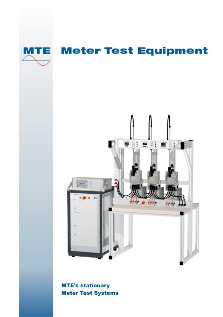
MTE's stationary Meter Test Systems - Belmet
MTE's stationary Meter Test Systems - Belmet
MTE's stationary Meter Test Systems - Belmet

You also want an ePaper? Increase the reach of your titles
YUMPU automatically turns print PDFs into web optimized ePapers that Google loves.
<strong>MTE's</strong> <strong>stationary</strong><br />
<strong>Meter</strong> <strong>Test</strong> <strong>Systems</strong>
System Overview<br />
The individual system components of a MTE<br />
meter test system such as a fully electronic<br />
voltage and current power source, a reference<br />
meter, an error evaluation system, as well as a<br />
meter test rack or gantry system are modulary<br />
developed and can be combined in any order.<br />
This modular design gives flexibility and enables<br />
MTE to provide the optimal customer orientated<br />
solution for each single or three phase meter test<br />
system the customer requires to meet the<br />
changing needs of the metering world.<br />
Innovative, economical, modular meter test<br />
systems enable the user to measure and check<br />
meters with high precision.<br />
<strong>Meter</strong> test systems are available for testing of<br />
single and three phase meters with or without<br />
closed I-P links.<br />
<strong>Meter</strong> test systems are available with fixed meter<br />
racks or with gantries and moveable trolleys to<br />
fulfill different requirements of production and test<br />
capacities.<br />
MTE <strong>Meter</strong> test systems are controlled by<br />
®<br />
CAMCAL for WINDOWS an easy to use and<br />
intuitive software package which is available in<br />
different languages.<br />
Configuration of a standard meter test system MTE-S<br />
System Measuring<br />
Modules SMM 400+<br />
Scanning Heads<br />
SH 2003<br />
Device Under <strong>Test</strong><br />
DUT<br />
STE 10<br />
Tariff circuit switching<br />
Voltage and current<br />
source SPE 120.3<br />
U L1 -U L3<br />
IL1-IL3<br />
Reference<br />
Standard SRS 121.3<br />
Reference<br />
pulses to SMMs<br />
RS232<br />
ETHERNET<br />
RS 232<br />
RS 232<br />
-1-
Electronic power sources<br />
SPE System, three phase power source<br />
The SPE System is an electronic voltage- and<br />
current power source and a meter supply unit<br />
(phantom load) for testing electricity meters or<br />
for testing other devices which use current or<br />
voltage.<br />
The cabinet is equipped with the following<br />
components:<br />
<br />
<br />
<br />
<br />
<br />
<br />
Control unit STE 10<br />
Power source SPE 120.3 with digital voltage<br />
and current amplifier<br />
Digital electronic reference meter SRS 121.3<br />
or other types (Option)<br />
Voltage and current ranges:<br />
Voltage: 30 V up to 300 V<br />
Current: 1 mA up to 120 A or<br />
1 mA up to 200 A<br />
Output power: 300 VAor 600 VAper phase<br />
Power efficiency: > 85 %<br />
PSP System, single up to three phase<br />
power sources<br />
The PSP System is an electronic voltage- and<br />
current power source and a meter supply unit<br />
(phantom load) for testing electricity meters or<br />
for testing other devices which use current or<br />
voltage.<br />
The cabinet is equipped with the following<br />
components:<br />
<br />
<br />
<br />
<br />
<br />
<br />
Control unit STE 10<br />
One up to three power sources PSP 10 with<br />
digital voltage and current amplifier<br />
Digital electronic reference meter SRS 121.3<br />
or other types (Option)<br />
Voltage and current ranges:<br />
Voltage: 30 V up to 300 V<br />
Current: 1 mA up to 120 A<br />
Output power per phase:<br />
Voltage: 800 VA<br />
Current: 1200 VA<br />
Power efficiency: > 85 %<br />
-2-
Electronic power sources<br />
ZVE System, single up to three phase power sources<br />
The ZVE Power Source was specially designed for use as an electro technical current and voltage<br />
generator in <strong>Meter</strong> <strong>Test</strong> <strong>Systems</strong> and also in other automatic test systems.<br />
The power source creates the current and voltages - the phantom load - required for measuring the<br />
meters. The network as generated by the ZVE system is completely distinct from that of the mains<br />
power supply. The generated values are, consequently, practically independent of the quality of the<br />
public power supply.<br />
The ZVE system is composed, in general terms, of the following principal units:<br />
<br />
<br />
<br />
<br />
<br />
<br />
<br />
One up to three Voltage power sources PSU 10<br />
One up to three Current power sources PSI 10<br />
Control unit STE 10<br />
Digital electronic reference meter SRS 121.3 or other types (Option)<br />
Voltage and current ranges:<br />
Voltage: 30 V up to 300 V<br />
Current: 1 mA up to 120 A or<br />
1 mA up to 200 A<br />
Output power per phase:<br />
Voltage: 1000 VA / 2000 VA / 4000 VA<br />
Current: 1000 VA / 2000 VA / 4000 VA<br />
Power efficiency: > 85 %<br />
-3-
Reference Standards and Comparator<br />
Stationary Reference Standards<br />
The electronic system reference standards in<br />
0.05 % or 0.02 % accuracy, are precision<br />
measurement units for all AC values, which are<br />
used in the measurement of energy. The wide<br />
measurement range and the high precision are<br />
the main characteristics of the reference<br />
standards.<br />
SRS 121.3, accuracy 0.05 %<br />
available in two versions:<br />
Current range: 1 mA ... 120 A or 1 mA ... 200 A<br />
SRS 400.3, accuracy 0.02 %<br />
Current range: 1 mA ... 120 A<br />
SRS 200.3, accuracy 0.02 %<br />
Current range: 1 mA ... 200 A<br />
PRS 400.3 Portable Reference Standard<br />
The PRS 400.3 reference standard of the modular<br />
system is based on the well-known digital measurement<br />
value retrieval, fast analogue-digital<br />
conversion and calculation of the values using<br />
fast signal processors. As opposed to the past,<br />
reference standards are not only used as standards<br />
for meter testing in a <strong>stationary</strong> meter test<br />
installation, but are also now predominantly used<br />
in the field for the measurement of all main<br />
parameters.<br />
K2006 Comparator<br />
The K2006 is a high accuracy comparator of<br />
accuracy class 0.01, especially suitable for use<br />
in metrological institutes and high precision<br />
measuring laboratories.<br />
Its ability to compare directly to an external DC<br />
reference allows easy traceability to national<br />
standards.<br />
Comparators are regularly used for checking of<br />
reference standard meters, for the calibration of<br />
precision current and voltage sources and for<br />
the verification of electrical standard measurements<br />
and electricity test systems.<br />
-4-
Error evaluation systems<br />
The modular Evaluation System SMM 400<br />
performs error calculation, testing of emitting<br />
contacts and communication to tariff device units<br />
to the meter under test.<br />
Four different versions covering customer´s<br />
requirements are available:<br />
<br />
<br />
<br />
<br />
<strong>Meter</strong> error calculator with SMM 400 busmaster<br />
without error display<br />
Basic meter error calculator with SMM 400<br />
bus-master and SMM 400 error calculator<br />
module<br />
Standard evaluation system with SMM 400+<br />
bus-master and SMM 400+ system evaluation<br />
module<br />
Extended evaluation system with SMM 400<br />
Bus-Master, SMM 400+ system evaluation<br />
module and addition IN/OUT module for 8 inand<br />
8 outputs and or COMM communication<br />
module<br />
Functions display and interfaces<br />
<br />
<br />
<br />
<br />
<br />
<br />
<strong>Meter</strong> error measurement with scanning head<br />
<strong>Meter</strong> error measurement of emitting contacts<br />
Impulse generator<br />
Graphic meter error display<br />
Reset button<br />
Communication interfaces RS 232, RS 485,<br />
CL, M-Bus and ETHERNET<br />
Options<br />
<br />
<br />
IN/OUT module for 8 in- and 8 pulse outputs<br />
and 10-30 VDC supply for S0 inputs<br />
COMM module with ETHERNET, M-Bus and<br />
RS 485 interfaces<br />
Personal Computer<br />
RS232<br />
Rearside<br />
of STE 10<br />
ETHERNET<br />
RS232<br />
Rearside<br />
of SRS 121.3<br />
fref<br />
Power Supply +24 V<br />
SMM-Bus<br />
Master<br />
fref<br />
+12V<br />
Pos. 1...n Pos. 1...n Pos. 1...n<br />
Extended evaluation system<br />
Standard evaluation system<br />
Basic meter error calculator<br />
<strong>Meter</strong> error calculator<br />
-5-
Error evaluation systems<br />
SMM 400 Bus-Master provides the interface<br />
between personal computer (via ETHERNET)<br />
and the system modules over RS 485-Ringbus.<br />
The SMM 400 Bus-Master is equipped with an<br />
error calculator for 10 meter position and 10<br />
direct inputs for scanning head pluses.<br />
SMM 400 is a one channel error calculator with<br />
one input on the rear side for scanning head<br />
pulse from SH 2003 or SH 11. A reset-button<br />
allows a restart of the measurement. The meter<br />
error is shown on full graphic OLED display.<br />
SMM 400+ <strong>Meter</strong> Evaluation Module with full<br />
graphic OLED display, reset-button and 2<br />
scanning head pulse inputs is the perfect solution<br />
to test modern meters.<br />
The sockets are used for:<br />
Socket : IN – and OUT of fast and slow pulses<br />
Socket D: Serial interface RS 232 and 20mA -<br />
current loop interface (CS)<br />
Socket IR: Serial infrared interface e.g. for<br />
readout of tariff devices with optical<br />
communication head OKK.<br />
The module IN/OUT is equipped with the<br />
following In- / Outputs:<br />
8 Pulse inputs (IN) for testing of meter emitting<br />
contacts<br />
8 Plus outputs (OUT) send pre-defined pulse<br />
to the meter under test<br />
The module COMM is equipped with the<br />
following interfaces:<br />
ETHERNET<br />
M-Bus interface<br />
RS 485 interface<br />
-6-
<strong>Meter</strong> test racks<br />
The meter test racks are made of robust aluminimum profiles. The rack consists of a working table,<br />
equipped with attachments for single- or three phase meters. Each meter position is equipped with an<br />
error evaluation system, safety sockets for the connection of the measuring voltage and lateral movable<br />
scanning head carriages with depth and height adjustments for the scanning heads.<br />
Thanks to the modular design structure of the meter test racks, special versions can be adapted easily<br />
with regard to the number of measurement positions, mechanical arrangements and technical<br />
specifications according to customer needs.<br />
The picture shows a meter test rack with 10 measurement positions. By request different options can be<br />
offered to the meter test system:<br />
<br />
<br />
<br />
<br />
Several quick connection devices according to IEC- or ANSI standards are available, which allow fast<br />
suspension and connection of meters<br />
Relay outputs for tariff control<br />
Hand held terminal with or without barcode reader<br />
Tariff readout system, etc.<br />
-7-
<strong>Meter</strong> test racks<br />
The picture shows a meter test rack with total 20 measurement positions in one row of ten on the front and<br />
one row of ten on the rear side.<br />
The picture shows a meter test rack for 5 ANSI meters with quick connection devices QCD Form S and<br />
isolation current transformers ICT 2.3<br />
-8-
Gantry <strong>Systems</strong> and Isolation <strong>Test</strong><br />
Gantry systems are generally used, if test and calibration of single and three phase meters with a high<br />
throughput are required. Whilst the fully automatic test of the meters with a trolley in the gantry system is<br />
running , a second trolley can be used in parallel to perform the assembly, preheating and if required<br />
meter isolation test.<br />
The suspension rack for the isolation can accomodate up to 5 meters. The devices under test are<br />
connected via quick connetion devices on a conductive aluminium plate by means of a tilting support<br />
frame, the status of the device under test can be determined.<br />
-9-
Customized test systems<br />
VXL Landis & Gyr Ltd., Calcutta,<br />
India, Six meter test systems<br />
Each of the six test system consists of an<br />
electronic power source type ZVE with<br />
4000 VA output power in voltage and<br />
current and each test system consists of<br />
six meter test racks with 26 positions,<br />
providing VXL Landis & Gyr Ltd with a<br />
total capacity of 936 positions for singlephase<br />
meters.<br />
ENEL, Italy, <strong>Meter</strong> test system for<br />
three-phase meters<br />
The photo shows a customized test system<br />
for ENEL meters. The test system is divided<br />
into three sections. In the left section the<br />
meters are assembled, in the middle<br />
section the meters are tested. Once tested<br />
they are removed from the test system in<br />
the right section therefore providing a<br />
continuous flow of assembled and tested<br />
meters.<br />
ELSTER, Hungary, <strong>Meter</strong> test system<br />
for 80 single-phase meters<br />
The meters are mounted on the front and<br />
the back of the trolleys in two rows. This<br />
customized and compact construction<br />
allows testing of 80 single-phase meters in<br />
tight floor space conditions.<br />
-10-
Modernization of existing test systems<br />
For customers already using MTE´s test<br />
systems for a long time it is of importance to<br />
have the option to utilize the well known<br />
technology also in the future. MTE has taken<br />
this issue serious in providing solutions to<br />
gradually replace existing systems with modern<br />
components.<br />
The example shows a Landis & Gyr test system<br />
ETALOGYR 6001 which was modernized in<br />
order to meet the constantly increasing requirements<br />
of meters and meter testing.<br />
Isolation current transformer ICT 2.3<br />
Scanning head SH 2003 and scanning head carriage SHC<br />
Quick connection device EMP 1.3<br />
Error display channel with<br />
system measuring modules SMM 400+<br />
Electronic power source SPE 120.3<br />
and system reference standard SRS 121.3<br />
-11-
<strong>Test</strong>ing of single phase meters with closed IP-links<br />
<strong>Test</strong> requirements with closed I-P links<br />
If the meters under test do not allow for opening of the I-P links, then there is an unwanted connection<br />
between voltage and current path at every meter position.<br />
Because of these connections, the line (input) and load (output) of each current measurement element<br />
are forced to be at the same potential, an effective short-circuit path exists across the current measuring<br />
circuit of every meter under test, causing a large measurement error. It is therefore not possible to test<br />
multiple meters with closed I-P connections on a conventional meter test installation without additional<br />
facilities. To be able to test these types of meters, galvanic isolation must be provided between the<br />
current and voltage circuits of each meter under test. This isolation must ensure that the closed I-P links<br />
in the meters do not cause these unwanted short-circuits and the resultant measurement errors. With<br />
single phase meters, galvanic isolation can theoretically be carried out using either voltage or current<br />
isolation transformers.<br />
In this case, a connected I-P link does not cause a short-circuit, as this connection is now made on the<br />
secondary side of the transformer, thus avoiding any direct connection with the other meters in the circuit.<br />
Voltage isolation for testing single-phase<br />
meters<br />
For the testing of multiple single-phase meters<br />
with fixed/closed links between the voltage and<br />
current path (I-P links), galvanic isolation must be<br />
provided at each test position.<br />
In practice this is normally done by connecting the<br />
voltage circuit of every meter under test, through<br />
a high accuracy voltage transformer. For cost<br />
reasons a voltage transformer with several<br />
galvanically isolated secondary windings is used.<br />
Reference Standard <strong>Meter</strong> 1 <strong>Meter</strong> 2<br />
<strong>Meter</strong> n<br />
Current<br />
source<br />
I<br />
Voltage<br />
source<br />
U<br />
Un<br />
Primary<br />
Sec 1<br />
Sec 2<br />
Sec n<br />
MSVT<br />
-12-
<strong>Test</strong>ing of three phase meters with closed IP-links<br />
Current isolation for testing of multiphase<br />
meters<br />
The ICT 2.3 three-phase Isolation Current<br />
Transformer is used on multi position test<br />
benches for testing three-phase meters with<br />
closed links between the current and voltage<br />
measuring circuits (IP-links). Electronic meters<br />
with closed links are becoming increasingly<br />
common.<br />
While testing meters with fix closed IP-links,<br />
unwanted connections between voltage and<br />
current path at each test position will cause<br />
significant accuracy reduction.<br />
In this case transformers in the current circuit are<br />
required to decouple the voltage from the current<br />
path.<br />
To achieve complete decoupling the test<br />
installation needs to be fitted with one current<br />
transformer per phase for each test position.<br />
<strong>Meter</strong> 1 <strong>Meter</strong> 2 <strong>Meter</strong> n<br />
Closed<br />
Links<br />
STE 10<br />
Tariff<br />
circuits<br />
<strong>Meter</strong> under test<br />
Voltage and<br />
current source<br />
SPE 120.3<br />
UL1-UL3<br />
IL1-IL3<br />
IL3<br />
IL2<br />
IL1<br />
UL1<br />
UL2<br />
UL3<br />
UN<br />
Reference<br />
Standard<br />
Isec<br />
Iprim<br />
Icomp<br />
Iprim Isec<br />
Current Source<br />
-13-
®<br />
Software package CAMCAL for Windows<br />
®<br />
CAMCAL for WINDOWS is a comprehensive<br />
software package designed to fulfil the<br />
requirements of the modern meter testing<br />
environment but also provides the flexibility to<br />
easily incorporate future meter testing<br />
requirements.<br />
This defines the data to be selected or<br />
programmed plus the dispatching commands,<br />
adaptable by the customer, makes the fully<br />
automatic examination of high-functional meters<br />
and tariff devices possible.<br />
®<br />
CAMCAL for WINDOWS software allows the<br />
control of both static and portable meter test<br />
equipment, including the recording and<br />
evaluation of meter and measurement data.<br />
®<br />
CAMCAL for WINDOWS software can be used<br />
throughout the meter test environment.<br />
<strong>Test</strong>s can be carried out for simple or highly<br />
complex meters in accordance with the customer<br />
requirements and national / international test and<br />
calibration regulations (e.g. PTB, IEC,ANSI).<br />
The user interface of the basic version shows all<br />
essential information required, therefore making<br />
the system easily understandable to operators with<br />
limited technical knowledge.<br />
®<br />
Advantages of CAMCAL for Windows<br />
<br />
<br />
<br />
<br />
<br />
<br />
<br />
User-friendly operation<br />
Database for meters and test sequences<br />
Fully-automatic test sequences for meter testing<br />
Transparent evaluation and presentation of<br />
results and statistics<br />
Suitable for use with various hardware<br />
combinations<br />
Modular system allows the integration of<br />
customer specific applications<br />
Operator interface available in several<br />
languages<br />
<strong>Meter</strong> type description<br />
The meter type description contains the electrical<br />
and functional definitions of meters under test<br />
(connection values, constants, registers, ...).<br />
For the tariff device communication, a communication<br />
module is assigned to the meter types.<br />
The basic version supports the communication<br />
protocol in accordance with that described in the<br />
IEC 62056-21 Mode C standard. As an additional<br />
option the communication protocol is prepared<br />
according to dlms / COSEM.<br />
<strong>Test</strong> sequence<br />
A test sequence describes the order and content of<br />
the various test steps in a sequence. For each test<br />
step the desired test quantities (current, voltage,<br />
phase angle, frequency, …) are specified.<br />
In addition to the respective test method (e.g. error<br />
measurement, register tests, …) each checkpoint<br />
can be linked with control commands. Control<br />
commands display for instance instructions to the<br />
operator, switching of tariff relays or dispatching of<br />
commands e.g. to adjust time, …<br />
-14-
®<br />
Software package CAMCAL for Windows<br />
<strong>Meter</strong> testing<br />
The user allocates to each active measurement<br />
position a meter type and selects a test<br />
sequence. Subsequently the user will<br />
comfortably be guided through the test. The<br />
actual status of the test and active test point is<br />
clearly indicated at all times.<br />
It is possible to display simultaneously the actual<br />
test values and/or results in their own windows<br />
using large, easily visible fonts.<br />
Results<br />
After executing an automatic test sequence all<br />
saved results are available for further data<br />
processing, such as creating an individual test<br />
report or export to Excel tables. The results can also<br />
be viewed and evaluated directly using several sort<br />
criteria in the database.<br />
Furthermore the CAMCAL Report Generator has<br />
the flexibility to add to reports logos, diagrams and<br />
fields (e.g. for signatures) etc.<br />
Additional standard functions of the CAMCAL<br />
for Windows Software<br />
<strong>Test</strong>ing of modern meters requires an adaptable<br />
and flexible software package. Because of its<br />
®<br />
modular design, CAMCAL for Windows covers<br />
this requirement.<br />
®<br />
CAMCAL for Windows Software meets the<br />
following requirements:<br />
<br />
<br />
<br />
<br />
<br />
<br />
<br />
Modular extensions of semi-automatic and<br />
fully automatic systems are possible without<br />
extensive software adaptations<br />
Demonstration programmes allow training to<br />
be given before delivery of the test system<br />
Standardized meter type and test sequence<br />
definitions considerably reduce the need for<br />
extensive training and familiarisation<br />
Data export modules support data transfer to<br />
other systems<br />
The operator interface is available in many<br />
different languages<br />
Password protection is provided for different<br />
user levels<br />
Import and export function enable the easy<br />
transfer of meter types , test sequences, report<br />
protocol masks etc. between test systems or<br />
across sites or between manufacturers and<br />
customers for instance<br />
Optional Software Modules<br />
<br />
<br />
<br />
<br />
<br />
<br />
Tariff device communication / dlms<br />
Generation of harmonics<br />
Tariff device testing with pulse transmitter<br />
Error compensation<br />
Generation of ripple control signals<br />
Generation of special test signals and wave<br />
forms according toIEC 62052-11<br />
IEC 62053-11/-21/-22<br />
®<br />
The CAMCAL Report Generator, enables the user<br />
to create and define there own protocol masks<br />
(calibration certificates, pass/fail reports, statistical<br />
reports, customer reports etc).<br />
-15-
Scanning heads and scanning head carriages<br />
Scanning head SH 2003<br />
The SH 2003 photoelectric scanning head is<br />
suitable for use with both LED impulses from<br />
static/electronic meters and also for detecing<br />
the marks on Ferraris/mechanical rotating disc<br />
meters, selectable via a switch. Due to its high<br />
performance and robust construction it is<br />
suitable for both <strong>stationary</strong> and portable test<br />
systems.<br />
Scanning head SH 11 with integrated<br />
teach function<br />
The SH 11 scanning head was especially<br />
designed for scanning of the marks on the<br />
rotating discs of Ferraris/mechanical meters or<br />
simulated disc marks on LCD displays plus the<br />
detection of light emitting diodes (LED's) of<br />
static/electronic meters. The choice of operation<br />
with mechanical or electronic meters is made<br />
by simple rotation of a selection switch. The<br />
manually sensibility set-up for the disc or LCD<br />
marks is not necessary.<br />
The optimal set-up is automatically learned by<br />
the integrated teach function, which can be<br />
activated by the rotary switch or an external<br />
control signal.<br />
Scanning head carriages<br />
SHC 1.2 and SHC 2.2<br />
The SHC range of scanning head carriages has<br />
been designed for use with the SH 2003 and<br />
SH 11 model scanning heads. The range is<br />
user friendly and offers a high degree of<br />
flexibility.<br />
<br />
<br />
<br />
<br />
Horizontal adjustment and scanning head<br />
fixing are built into each individual support<br />
position<br />
Depth adjustment has also been provided in<br />
order to adapt the scanning head to meters of<br />
diverse constructional depths<br />
Fast height adjustment by using the direct<br />
'press-button' control<br />
There is a fine setting control, both in depth<br />
and height, for each version of the scanning<br />
head. <strong>Meter</strong>s may be scanned from the side by<br />
simple rotation of the fine setting<br />
-16-
Quick connection devices<br />
Quick connection device QCD<br />
This QCD quick connector may be used with<br />
current levels up to 80 A for long period testing,<br />
and with up to 100 A for short periods of time.<br />
The connector is available in three different<br />
versions, which may be used together with<br />
single and three phase meters.<br />
The QCD 3 I/U is constructed identically to the<br />
QCD 3 I, with the difference that the voltage<br />
connection is assured over a jumping finger<br />
contact system.<br />
Quick connection device EMP 1.3<br />
The EMP 1.3 Quick Connection Device is used<br />
together with Electricity <strong>Meter</strong> <strong>Test</strong> <strong>Systems</strong>, and<br />
is especially recommended for situations where<br />
the time factor is of importance.<br />
Thanks to the universal construction of the EMP<br />
1.3 quick connection device, it may be used for<br />
the support and connection of practically all types<br />
of electricity meters.<br />
This EMP 1.3 quick connection device can be<br />
used with current levels up to 100 A testing, and<br />
even with the additional high current adapters up<br />
to 120A.<br />
Quick connection device QCD Form S<br />
Due to its universal construction the QCD Form<br />
S Universal Quick Connection Device may be<br />
used for the support and connection of<br />
practically all types of self contained (direct<br />
connected) or transformer operated ANSI<br />
socket meters, including the most used Forms<br />
1S, 2S, 3S, 4S, 5S, 6S, 8S, 9S, 12S, 13S, 14S,<br />
15S, 16S, 17S.<br />
This QCD Form S Universal Quick Connection<br />
Device can be used with current levels up to<br />
200 A.<br />
-17-
Accessories and Options<br />
Hand Held Terminals<br />
The HT 2010 wireless hand held terminal with an<br />
integrated bar code reader is designed for<br />
recording meter specific data at meter test<br />
systems.<br />
Impulse InterfaceAdapter<br />
The IMP-IF1 interface adapter is suitable to<br />
interface MTE reference standards with meters<br />
having retransmitting contacts, open-collector<br />
transistor outputs or true S0-outputs to allow full<br />
testing of meters with these types of outputs<br />
interfaces.<br />
OKK optical communication head<br />
The communication to sophisticated electronic<br />
tariff devices/meters is performed according to<br />
IEC61107 Mode C, using an OKK optical<br />
communication head.<br />
The OKK is directly connected to the<br />
corresponding interface of the measuring module<br />
SMM 400.<br />
Accessories for quick connection<br />
devices<br />
<br />
<br />
<br />
<br />
Adapter to electronic meters for fast<br />
connection of the measuring voltage<br />
Voltage contacts for transformer connected<br />
meters<br />
Customized meter templates for fast<br />
assembly of the quick connection device<br />
High current screw adapter for currents up to<br />
120A<br />
-18-
The following MTE brochures are available:<br />
Stationary <strong>Meter</strong> <strong>Test</strong> <strong>Systems</strong>: Fixed Rack <strong>Systems</strong> / Gantry-Trolley System / Customized System<br />
Comparator:<br />
K2006<br />
Portable Reference Standards: PRS 400.3 / CALPORT 300<br />
Portable Working Standards:<br />
PWS 3.3 / PWS 2.3 PLUS<br />
Portable Standard <strong>Meter</strong>s: Check<strong>Meter</strong> 2.3 / Check<strong>Meter</strong> 2.1<br />
Portable Power Sources: PPS 400.3 / PPS 3.3 C / CheckSource 2.3<br />
Portable <strong>Test</strong> <strong>Systems</strong>: PTS 2.3 C / PTS 3.1 C / PTS 3.3 C / PTS 400.3 / CheckSystem 2.1 / CheckSystem 2.3<br />
Instrument Transformer <strong>Test</strong>er: PTT 2.1<br />
Transformer Monitoring <strong>Systems</strong>: HYDROCAL 1001 / HYDROCAL 1002 / HYDROCAL 1003 / HYDROCAL 1005 / HYDROCAL 1008<br />
Software:<br />
CAMCAL for Windows / CALSOFT I / II<br />
MTE <strong>Meter</strong> <strong>Test</strong> Equipment AG<br />
Dammstrasse 16<br />
P.O. box 4544<br />
CH-6304 Zug, Switzerland<br />
Phone: +41 (41) 724 24 48<br />
Fax: +41 (41) 724 24 25<br />
Internet: www.mte.ch<br />
e-mail: info@mte.ch<br />
EMH Energie-Messtechnik GmbH<br />
Vor dem Hassel 2<br />
D-21438 Brackel, Germany<br />
Phone: +49 (4185) 58 57 0<br />
Fax: +49 (4185) 58 57 68<br />
Internet: www.emh.de<br />
e-mail: info@emh.de<br />
MTE - India Office<br />
115, Navjiwan Vihar<br />
New Delhi - 110017, India<br />
Phone: +91 (11) 2669 10 17<br />
Mobile: +91 (98) 911 12000<br />
Fax: +91 (11) 2669 24 91<br />
e-mail: vinarora@vsnl.com<br />
EMH Energie-Messtechnik (Beijing) Co. Ltd.<br />
Section 305, Building 2, Ke-Ji-Yuan<br />
Nr.1 Shangdi-Si-Jie, Shangdi-Information-Industry-Base<br />
Haidian District<br />
Beijing 100 085<br />
P.R. China<br />
Phone: +86 (10) 629 81 227<br />
Mobile: +86 (139) 0 103 6875<br />
Fax: +86 (10) 629 88 689<br />
e-mail: guo@emh.com.cn<br />
MTE <strong>Meter</strong> <strong>Test</strong> Equipment (UK) Ltd<br />
4 Oval View<br />
Woodley Stockport<br />
Cheshire SK6 1JW, England<br />
Phone: +44 (161) 406 9604<br />
Fax: +44 (161) 406 9605<br />
Internet: www.mte.ch<br />
e-mail: info@mte.uk.net<br />
OOO MTE<br />
Pochtovaja Bolshaja str., 26, bld. 1, office 501<br />
105082 Moscow, Russian Federation<br />
Phone: +7 (495) 640 07 25<br />
Internet: www.meter-test.ru<br />
e-mail: info@meter-test.ru<br />
MTE <strong>Meter</strong> <strong>Test</strong> Equipment AG<br />
Dammstrasse 16 • P.O. box 4544 • 6304 Zug • Switzerland<br />
Phone +41 (41) 724 24 48 • Fax +41 (41) 724 24 25 • Internet www.mte.ch<br />
Edition 01.2011<br />
Subject to alterations