Specifications - Maxtech
Specifications - Maxtech
Specifications - Maxtech
Create successful ePaper yourself
Turn your PDF publications into a flip-book with our unique Google optimized e-Paper software.
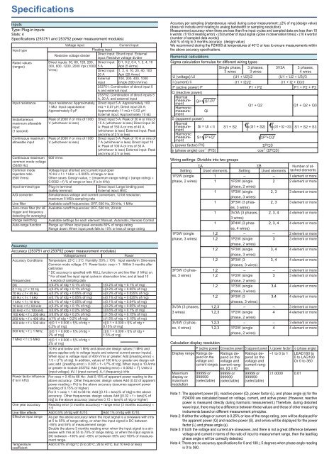
<strong>Specifications</strong><br />
Inputs<br />
Type: Plug-in inputs<br />
Slots: 4<br />
<strong>Specifications</strong> (253751 and 253752 power measurement modules)<br />
Voltage input<br />
Current input<br />
Input type<br />
Floating input<br />
Resistive voltage divider<br />
Direct input: Shunt input External<br />
input: Resistive voltage divider<br />
Rated values<br />
Direct inputs: 30, 60, 120, 200, Direct input<br />
(ranges)<br />
300, 600, 1200, 2000 Vpk (1000 5 A<br />
Vrms)<br />
Input resistance<br />
Instantaneous<br />
maximum allowable<br />
input<br />
(1 second)<br />
Continuous maximum<br />
allowable input<br />
Continuous maximum 600 Vrms<br />
common mode voltage<br />
(50/60 Hz)<br />
Common mode<br />
rejection ratio<br />
(600 Vrms)<br />
Input terminal type<br />
A/D converter<br />
Line filter<br />
Zero-cross filter (for HF<br />
trigger and frequency<br />
detecting for averaging)<br />
Range switching<br />
Auto-range function<br />
Input resistance: Approximately<br />
1 MΩ Input capacitance:<br />
Approximately 5 pF<br />
Peak of 2000 V or rms of 1000<br />
V (whichever is less)<br />
Peak of 2000 V or rms of 1000<br />
V (whichever is less)<br />
Direct input<br />
20 A<br />
External<br />
input<br />
0.1, 0.2, 0.4, 1, 2, 4, 10<br />
Apk (5 Arms)<br />
1, 2, 4, 10, 20, 40, 100<br />
Apk (20 Arms)<br />
100, 200, 400, 1000<br />
mVpk (500 mVrms)<br />
253751: Combination of direct input 5<br />
A and external input<br />
253752: Combination of direct inputs 5<br />
A, 20 A, and external input<br />
Direct input 5 A: Approximately 100<br />
mΩ + 0.07 µH, Direct input 20 A:<br />
Approximately 11 mΩ + 0.02 µH<br />
External input: Approximately 10 kΩ<br />
Direct input 5 A: Peak of 30 A or rms of<br />
15 A (whichever is less) Direct input 20<br />
A: Peak of 150 A or rms of 40 A<br />
(whichever is less) External input: Peak<br />
and rms of 2 V or less<br />
Direct input 5 A: Peak of 10 A or rms of<br />
7 A (whichever is less) Direct input 10<br />
A: Peak of 100 A or rms of 30 A<br />
(whichever is less) External input: Peak<br />
and rms of 2 V or less<br />
Voltage input shorted and current input open<br />
10 Hz ≤ f ≤ 1 kHz: ± 0.005% of range or less<br />
Other cases: Design value, ± ((maximum range rating) / (range rating) ×<br />
0.0002 × f) % of range or less (f is in kHz)<br />
Plug-in terminal<br />
Direct input: Large binding post<br />
(safety terminal)<br />
External input: BNC<br />
Simultaneous voltage and current conversion, 12-bit resolution,<br />
maximum 5 MS/s sampling rate<br />
Available cutoff frequencies: OFF, 500 Hz, 20 kHz, 1 MHz<br />
Available cutoff frequencies: OFF, 500 Hz, 20 kHz<br />
Available settings for each element: Manual, Automatic, Remote Control<br />
Range up: When input peak exceeds 80% of range rating<br />
Range down: When input peak falls to 15% or less of range rating<br />
Accuracy<br />
Accuracy (253751 and 253752 power measurement modules)<br />
Voltage/current<br />
Power<br />
Accuracy Conditions Temperature: 23°C ± 3°C Humidity: 50% ± 10% Input waveform: Sine-wave<br />
Common mode voltage: 0 V Power factor: cosφ = 1 Within 3 months after<br />
calibration<br />
* DC accuracy is specified with NULL function on and line filter (1 MHz) on.<br />
* For at least five input signal cycles in observation time, and at least 10<br />
Frequencies<br />
DC<br />
0.1 Hz ≤ f < 10 Hz<br />
10 Hz ≤ f < 45 Hz<br />
45 Hz ≤ f ≤ 1 kHz<br />
1 kHz < f ≤ 10 kHz<br />
10 kHz < f ≤ 50 kHz<br />
50 kHz < f ≤ 100 kHz<br />
100 kHz < f ≤ 200 kHz<br />
200 kHz < f ≤ 400 kHz<br />
400 kHz < f ≤ 500 kHz<br />
k words of sampling data<br />
±(0.2% of rdg + 0.1% of rng)<br />
±(0.2% of rdg + 0.1% of rng)<br />
±(0.2% of rdg + 0.05% of rng)<br />
±(0.1% of rdg + 0.05% of rng)<br />
±(0.1% of rdg + 0.05% of rng)<br />
±(0.2% of rdg + 0.1% of rng)<br />
±(0.6% of rdg + 0.2% of rng)<br />
±(0.6% of rdg + 0.2% of rng)<br />
±(1% of rdg + 0.2% of rng)<br />
±[(0.1 + 0.006 × f)% of rdg +<br />
0.2% of rng]<br />
±(0.2% of rdg + 0.1% of rng)<br />
±(0.2% of rdg + 0.05% of rng)<br />
±(0.2% of rdg + 0.025% of rng)<br />
±(0.1% of rdg + 0.025% of rng)<br />
±(0.1% of rdg + 0.04% of rng)<br />
±(0.2% of rdg + 0.05% of rng)<br />
±(0.6% of rdg + 0.1% of rng)<br />
±(1.5% of rdg + 0.15% of rng)<br />
±(1.5% of rdg + 0.15% of rng)<br />
±[(0.1 + 0.009 × f)% of rdg +<br />
0.15% of rng]<br />
500 kHz < f ≤ 1 MHz<br />
1 MHz < f ≤ 5 MHz<br />
Power factor influence<br />
(f is in kHz)<br />
±[(0.1 + 0.006 × f)% of rdg +<br />
2% of rng]<br />
±[(0.1 + 0.006 × f)% of rdg +<br />
2% of rng]<br />
±[(0.1 + 0.009 × f)% of rdg +<br />
1.5% of rng]<br />
10 Hz and below and 1 MHz and above are design values (1 MHz and<br />
above applies only to voltage inputs and external current sensor inputs).<br />
When input is voltage input of 400 Vrms or greater: Add [(reading error) ×<br />
1.5 × U 2 % of rdg]. In addition, values of 100 kHz or greater are design values;<br />
add [(reading error) × 0.005 × f × U 2 % of rdg]. When input is 10 Arms<br />
or greater in module 253752: Add [(reading error) × 0.0002 × I 2 ]. Units U<br />
(input voltage): kV, I (input current): A, f (frequency): kHz<br />
For cosφ = 0 45 to 66 Hz: Add 0.15% of apparent power reading to the<br />
above accuracy. Other frequencies: design values Add (0.02 of apparent<br />
power reading × f%) to the above accuracy (assumes apparent power<br />
reading of 0.15% or higher)<br />
For 0 < cosφ < 1 45 to 66 Hz: Add [(0.15 × tanφ)% of rdg] to the above<br />
accuracy. Other frequencies: design values Add [(0.02 × f × tanφ)% of<br />
rdg] to the above accuracy (assumes 0.15 × tanφ% of rdg or higher)<br />
One year accuracy Reading error (3 months accuracy) + range error (3 months accuracy) ×<br />
1.5<br />
Line filter effects Add 0.5% of rdg with fc/10. Add 1% of rdg with fc/10.<br />
Effective input range As per the above accuracy when the input signal is a sinewave with rms<br />
at 5 to 55% of range rating, or when the input signal is DC between<br />
–55% and 55% of measurement range.<br />
Double the above 3 months reading error when the input signal is a sinewave<br />
with rms at 55 to 70% of range rating, or when the input signal is<br />
DC between –100% and –55% or between 55% and 100% of measurement<br />
range.<br />
Temperature<br />
Add 0.01% of rdg/°C (5 to 20°C, 26 to 40°C, but 10 kHz or less)<br />
coefficient<br />
Accuracy per sampling (instantaneous value) during cursor measurement: ±2% of rng (design value)<br />
(does not include error relating to analog bandwidth or sampling resolution)<br />
Measurement accuracy when there are less than five input cycles and sampled data are less than 10<br />
k words: (1/10 of reading error) × (5/(number of input signal cycles in observation time)) × (10 k words/<br />
(number of sampled data words))<br />
Add % of rdg to 3 months accuracy (design value)<br />
We recommend storing the PZ4000 at temperatures of 40°C or less to ensure measurements within<br />
the above accuracy specifications.<br />
Numerical calculations<br />
Sigma calculation formulas for different wiring types<br />
U (voltage) Ui<br />
I (current) Ii<br />
P (active power) P<br />
Q (reactive power)<br />
Normal<br />
measurement<br />
Qi= Si 2 -Pi 2<br />
Harmonic<br />
measurement<br />
Qi<br />
S (apparent power)<br />
Normal<br />
measurement<br />
Si = Ui × Ii<br />
Harmonic<br />
measurement<br />
λ (power factor) P/S<br />
φ (phase angle) cos -1 (P/S)<br />
Single phase,<br />
3 wires<br />
S1 + S2<br />
3 phases,<br />
3 wires<br />
3V3A<br />
3 phases,<br />
4 wires<br />
(U1 + U2)/2 (U1 + U2 + U3)/3<br />
(I1 + I2)/2 (I1 + I2 + I3)/3<br />
P1 + P2<br />
P1 + P2 + P3<br />
Q1 + Q2<br />
3 (S1 + S2) 3 (S1 + S2 + S3)<br />
2<br />
3<br />
S= P 2 +Q 2 ΣP 2 +ΣQ 2<br />
Wiring settings: Divisible into two groups<br />
1P2W (single<br />
phase, 2 wires)<br />
1P3W (single<br />
phase, 3 wires)<br />
3P3W (3 phases,<br />
3 wires)<br />
3V3A (3 phases,<br />
3 wires)<br />
3V4W (3 phases,<br />
4 wires)<br />
ΣP/ΣS<br />
cos -1 (ΣP/ΣS)<br />
ΣA<br />
ΣB<br />
Setting Used elements Setting Used elements<br />
1<br />
1<br />
1<br />
1<br />
1<br />
1<br />
1,2<br />
1,2<br />
1,2<br />
1,2<br />
1,2<br />
1,2<br />
1,2<br />
1,2<br />
1,2,3<br />
1,2,3<br />
1,2,3<br />
1,2,3<br />
–<br />
1P2W (single<br />
phase, 2 wires)<br />
1P3W (single<br />
phase, 3 wires)<br />
3P3W (3 phases,<br />
3 wires)<br />
3V3A (3 phases,<br />
3 wires)<br />
3P4W (3 phases,<br />
4 wires)<br />
–<br />
1P2W (single<br />
phase, 2 wires)<br />
1P3W (single<br />
phase, 3 wires)<br />
3P3W (3<br />
phases, 3 wires)<br />
–<br />
1P2W (single<br />
phase, 2 wires)<br />
1P3W (single<br />
phase, 3 wires)<br />
3P3W (3<br />
phases, 3 wires)<br />
–<br />
1P2W (single<br />
phase, 2 wires)<br />
–<br />
1P2W (single<br />
phase, 2 wires)<br />
–<br />
2<br />
2, 3<br />
2, 3<br />
2, 3, 4<br />
2, 3, 4<br />
–<br />
3<br />
3, 4<br />
3, 4<br />
–<br />
3<br />
3,4<br />
3,4<br />
–<br />
4<br />
–<br />
4<br />
Q1 + Q2 + Q3<br />
S1 + S2 + S3<br />
Number of attached<br />
elements<br />
1 element or more<br />
2 element or more<br />
3 element or more<br />
3 element or more<br />
4 element or more<br />
4 element or more<br />
2 element or more<br />
3 element or more<br />
4 element or more<br />
4 element or more<br />
2 element or more<br />
3 element or more<br />
4 element or more<br />
4 element or more<br />
3 element or more<br />
4 element or more<br />
3 element or more<br />
4 element or more<br />
Calculation display resolution<br />
P (active power) Q (reactive power) S (apparent power) λ (power factor) φ (phase angle)<br />
Display range Ratings depend<br />
on the<br />
voltage and<br />
Ratings depend<br />
on the<br />
voltage and<br />
Ratings depend<br />
on the<br />
voltage and<br />
–1 to 0 to 1 LEAD180 to<br />
0 to LAG180<br />
Or 0 to 360<br />
current ranges. current ranges.<br />
(Q ≥ 0)<br />
current ranges.<br />
Maximum<br />
display or<br />
maximum<br />
resolution<br />
99999 or<br />
999999<br />
(selectable)<br />
99999 or<br />
999999<br />
(selectable)<br />
99999 or<br />
999999<br />
(selectable)<br />
±1.0000 0.01<br />
Note 1: The apparent power (S), reactive power (Q), power factor (λ), and phase angle (φ) for the<br />
PZ4000 are calculated based on voltage, current, and active power. (However, reactive<br />
power is measured directly during harmonic measurement.) Therefore, during distorted<br />
wave input, there may be a difference between these values and those of other measuring<br />
instruments based on different measurement principles.<br />
Note 2: If either the voltage or current is 0.25% or less of the range rating, zero will be displayed for<br />
the apparent power (Q) and reactive power (S), and errors will be displayed for the power<br />
factor (λ) and phase angle (φ).<br />
Note 3: If both the voltage and current are sinewaves, and there is not a great difference between<br />
voltage and current in terms of the ratio of input to measurement range, then the lead/lag<br />
phase angle φ will be correctly detected.<br />
Note 4: There are no accuracy specifications for 0 and 180 ± 5 degrees when phase angle reading<br />
is 0 to 360.
Measurement function items:<br />
U (voltage), I (current), P (active power), S (apparent power), Q (reactive power), λ (power<br />
factor), φ (phase angle), CF (crest factor), FF (form factor), |Z| (impedance), RS and RP<br />
(resistance), XS and XP (reactance), η and 1/η (efficiency), PC (Corrected Power), F1 to<br />
F4 (user-defined functions)<br />
Delta computation (during normal measurement only):<br />
Calculated by taking the sum or difference of instantaneous voltage and current values<br />
One of the following can be selected.<br />
Measurement parameters: ∆Urms, ∆Umn, ∆Udc, ∆Uac, ∆Irms, ∆Imn, ∆Idc, ∆Iac<br />
u1–u2: Voltage only<br />
i1–i2: Current only<br />
3-phase 3-wire/3V3A conversion<br />
Y–∆ conversion: Phase voltage–line voltage conversion, neutral line current<br />
∆–Y conversion: Line voltage–phase voltage conversion, neutral line current<br />
Waveform calculations<br />
Parameters<br />
Voltage and current of any element<br />
Waveform calculations 2 types (MATH1 and MATH2)<br />
ITEM<br />
C1 to C8: CH1 to CH8 data<br />
Memory size<br />
100 k words (if MATH1 and MATH2 are both used, then<br />
100 k words each)<br />
Arithmetic calculations Addition, subtraction, multiplication, division<br />
Special functions<br />
AVG( )<br />
Exponential average of instantaneous value<br />
TREND( ), TRENDM( ), TRENDD( ) Average data for each cycle<br />
When C1 to C8 are inserted<br />
TREND( )<br />
Root mean square values (true RMS)<br />
TRENDM( )<br />
Rectified MEAN value converted into an RMS value<br />
(MEAN)<br />
TRENDD( )<br />
Average (DC)<br />
Power average values (active power) for C1*C2, C3*C4, C5*C6, C7*C8. Only the<br />
following can be set in the parentheses: one item, C1*C2, C3*C4, C5*C6, C7*C8.<br />
(functions can not be entered in parentheses.)<br />
TRENDF( )<br />
Frequency data for each cycle, when C1 to C8 is inserted.<br />
Other functions<br />
ABS, SQR, SQRT, LOG, LOG10, EXP, NEG, TINTG, DIF<br />
FFT<br />
Type<br />
PS (power spectrum)<br />
Number of points 1000 points, 2000 points, 10000 points<br />
Window functions Rectangular, Hanning<br />
Measured parameters Voltage and current rms values, active power<br />
Starting point can be specified.<br />
Motor Evaluation Functions (sensor input module 253771) NEW<br />
Computing item:<br />
torque, revolution speed, mechanical power, synchronous<br />
speed, slip, motor efficiency, total efficiency and X-Y display<br />
for these items<br />
Torque / Revolution speed computing analog input<br />
Input resistance Approx. 1MΩ, approx. 17pF<br />
Accuracy<br />
±(0.1% of rdg + 0.05% of rng)<br />
Input range<br />
1 /2 /5 /10 /20 /50Vpk<br />
Maximum rated input 25Vrms<br />
Temperature coefficient ±0.03% of rdg/°C<br />
Revolution speed computing pulse input<br />
Input resistance Approx. 1MΩ, approx. 17pF<br />
Accuracy<br />
±(0.05% of rdg)<br />
Observation time need over 300 cycle pulses<br />
Maximum input range ±5Vpk<br />
Effective input range Minimum 1Vp-p<br />
Input waveform Rectangular waveform (duty ratio 50%)<br />
Pulse-revolution number transfer response 1 cycle of input frequency<br />
Effective frequency range 2kH to 200kHz (counter clock frequency 8MHz)<br />
250Hz to 8kHz (counter clock frequency 1MHz)<br />
16Hz to 800Hz (counter clock frequency 62.5kHz)<br />
1Hz to 40Hz (counter clock frequency 3906.25Hz)<br />
Note: Sensor input module 253771 can use Element 4 slot only.<br />
Select either analog or pulse for revolution speed computing input.<br />
Frequency measurements<br />
Measurement type Reciprocal<br />
Measured parameters Voltage and current values of all installed power<br />
measurement modules (only channels set to SYNC source<br />
during harmonic analysis).<br />
Maximum display<br />
99999 (2.5000 MHz max)<br />
Accuracy<br />
For observation period of 2 ms or longer<br />
10 Hz ≤ f < 10 kHz ±0.1% of rdg + 1 digit<br />
Assumes sinewave with input of at least 15% of range; 5<br />
cycles or more within observation period; and measured<br />
frequency no greater than 1/2.5 of sampling rate.<br />
Frequency measurement filter Set using zero-cross filter.<br />
Harmonic measurement<br />
Measurement type PLL synchronization<br />
Measured frequency range Fundamental wave frequency range of 20 Hz to 6.4 kHz<br />
Measured function items:<br />
U, I, P, S, Q, λ, φ (between V and A) for each order, φU, φI (phase difference for harmonic<br />
component relative to fundamental wave), |Z|, Rs, Rp, Xs, Xp,<br />
TOTAL U, I, P, S, Q, λ (Σ calculation possible), and φ<br />
U, I, and P harmonic distortion factor of each order<br />
U, I, and P THD<br />
PLL synchronization frequencies<br />
UTHF (voltage telephone harmonic factor), ITHF (current telephone harmonic factor),<br />
UTIF (voltage telephone influence factor), ITIF (current telephone influence factor), HVF<br />
(harmonic voltage factor), HCF (harmonic current factor)<br />
Set record length<br />
Same as normal.<br />
FFT data points 8192<br />
FFT analysis data starting point in acquisition memory can<br />
be set as desired.<br />
FFT processing word length 32 bits<br />
Window function<br />
Rectangular<br />
PLL synchronization options Either external clock or voltage/current in all installed power<br />
measurement modules can be selected. external clock can<br />
also be used without PLL. When this is done, the<br />
fundamental frequency is 1/4096 of the external clock.<br />
PLL synchronization filter Set using zero-cross filter.<br />
Anti-aliasing filter<br />
Set using line filter (fc = 20 kHz)<br />
Relationships between sampling rate, window width, and number of analysis orders<br />
Fundamental frequency Sampling Window Maximum Maximum number<br />
(Hz)<br />
rate (Hz) width number of of analysis orders<br />
analysis orders<br />
equal to normal<br />
with accuracy<br />
measurement accuracy<br />
20 Hz ≤ f < 40 Hz<br />
40 Hz ≤ f < 80 Hz<br />
80 Hz ≤ f < 160 Hz<br />
160 Hz ≤ f < 320 Hz<br />
320 Hz ≤ f < 640 Hz<br />
640 Hz ≤ f < 1.28 kHz<br />
1.28 kHz ≤ f < 2.56 kHz<br />
2.56 kHz ≤ f < 6.4 kHz<br />
f × 4096<br />
f × 2048<br />
f × 1024<br />
f × 512<br />
f × 256<br />
f × 128<br />
f × 64<br />
f × 32<br />
2<br />
4<br />
8<br />
16<br />
32<br />
64<br />
128<br />
256<br />
500<br />
500<br />
500<br />
200<br />
100<br />
50<br />
30<br />
15<br />
Note 1: Hysteresis is applied across each of the above fundamental frequency bands.<br />
Measurement accuracy Accuracy for bands where normal measurement accuracy<br />
is not applied: Add [0.001 × f × (order number)% of reading]<br />
(design value) Where f (in kHz) is the frequency for that<br />
order.<br />
Display<br />
Display<br />
6.4-inch color TFT liquid crystal display<br />
Pixel area for full display 640 × 480 (The liquid crystal display may contain<br />
approximately 0.02% defects among all display pixels.)<br />
Pixel area for waveform 501 × 432<br />
Display area<br />
Numerical<br />
Normal measurement: 8 values values, 16 values,<br />
42 values, 78 values, ALL<br />
Harmonic measurement:8 values, 16 values, Single List, Dual<br />
List, ∑ List<br />
Waveforms<br />
Single, Dual, Triad, Quad<br />
Vector<br />
Phase diagram for fundamental component during harmonic<br />
measurement<br />
Bar<br />
Bar graph up to maximum number of analysis orders during<br />
harmonic measurement<br />
Simultaneous display Numerical value + waveform, numerical value + bar,<br />
waveform + bar<br />
X-Y display Any one of the following can be selected for the X-axis :<br />
CH1-CH8, MATH1, MATH2. The rest of these are<br />
simultaneously displayed on the Y-axis.<br />
Alarm display<br />
Displayed on screen (only sensed during observation<br />
period).<br />
Peak over: When instantaneous value exceeds<br />
approximately 125% of range<br />
Maximum number of waveform display traces 24 traces (during zooming): 8 captured waveforms +<br />
16 zoomed waveforms<br />
Display updating cycle Depends on the observation time and record length. The<br />
display updating cycle is approximately 2 seconds in normal<br />
measurement mode, using a 100 ms observation time,<br />
100 k word record length setting, and 8 channels, with<br />
numerical value calculation ON and waveform calculation<br />
off.<br />
The display updating cycle is approximately 2 seconds in<br />
harmonic measurement mode, using a 100 ms observation<br />
period, 100 k word record length setting, and 8 channels,<br />
with numerical value calculation ON and waveform<br />
calculation off.<br />
Memory<br />
Set record length<br />
Record length settings<br />
50<br />
50<br />
50<br />
25<br />
25<br />
10<br />
10<br />
–<br />
100 k word/CH (standard), 1 M word/CH (with /M1 option),<br />
4 M word/CH(with /M3 option)<br />
100 k word, 1 M word, 4 M word (or 50 k word, 500 k word,<br />
and 2 M word when record length is divided; screen data<br />
are saved and measurement is ended when the STOP<br />
button is pressed) The sampling rate is selected<br />
automatically when the record length and observation time<br />
are set.<br />
Triggers<br />
Modes<br />
Off, Auto, Auto Level, Normal, and (with edge trigger)<br />
HF Auto, HF Normal<br />
Types<br />
Edge, window<br />
Sources<br />
INT (channels 1 through 8), and (with edge trigger) EXT<br />
Slopes<br />
Rising, falling, both<br />
Trigger position 0% to 100%<br />
HF cutoff frequency: set using zero-cross filter.<br />
When HF is selected as the trigger mode, the trigger level<br />
cannot be set.<br />
Screen data output and saving (copying)<br />
Internal printer (optional) Screenshot hard copies<br />
Floppy disks and external SCSI devices (optional) Formats: PostScript, TIFF, BMP<br />
Centronics port Formats: ESC-P, ESC-P2, LIPS3, PR201, PCL5, BJ<br />
External I/O<br />
EXT TRIG IN (external trigger input)<br />
Connector<br />
BNC<br />
Input voltage CMOS level (L: 0 to 1 V, H: 4 to 5 V)<br />
Minimum pulse width 1 µs<br />
Trigger delay time (2 µs + 1 sample cycle) or less<br />
EXT TRIG OUT (external trigger output)<br />
Connector<br />
BNC<br />
Input voltage CMOS level (L: 0 to 1 V, H: 4 to 5 V)<br />
Output delay time (1 µs + 1 sampling cycle) or less<br />
Output holding time Low level 200 ns or longer<br />
EXT CLK (external sampling clock input)<br />
Connector<br />
BNC<br />
Input voltage CMOS level (L: 0 to 1 V, H: 4 to 5 V)<br />
Input frequency range 1 kHz to 250 kHz (50% duty)<br />
20 Hz to 6.4 kHz when used as PLL source for harmonic analysis. 4096 times the<br />
fundamental frequency when used as a sampling clock for<br />
harmonic analysis. (The external clock is internally sampled<br />
at 20 MHz.)<br />
Internal floppy drive<br />
Size<br />
3.5 inches<br />
Formats<br />
640 KB, 720 KB, 1.2 MB, 1.44 MB<br />
7
GPIB port<br />
Electrical and mechanical specifications<br />
Compliant with IEEE Standard 488-1978.<br />
Functional specifications SH1, AH1, T6, L4, SR1, RL1, PP0, DC1, DT0, C0<br />
Protocol Compliant with IEEE Standard 488.2 1987.<br />
Serial (RS-232) port<br />
Connector<br />
D-Sub 9-pin<br />
Standard<br />
EIA-574 standard (for EIA-232 (RS-232) standard 9-pin<br />
connector)<br />
Bit rates<br />
1200, 2400, 4800, 9600, 19200 bps<br />
Centronics port<br />
Connector<br />
D-Sub 25-pin<br />
SCSI port (optional)<br />
Standard<br />
Small Computer System Interface (SCSI) ANSI X3.131-<br />
1986<br />
Connector<br />
Half-pitch 50-pin (pin type)<br />
Connector pin assignment Unbalanced (single-end), built-in terminator<br />
Usable hard drives SCSI hard drives, NEC MS-DOS Ver. 3.3 or higher, or EZ-<br />
SCSI drives that are formattable.<br />
Usable MO drives Drive capacities up to 640 MB are supported.<br />
Other drive types ZIP and PD drives can be used.<br />
For further information, please contact your nearest YOKOGAWA dealer.<br />
General specifications<br />
Warmup time<br />
Approximately 30 minutes<br />
Operating temperature and humidity ranges<br />
5 to 40°C, 20 to 85% RH (or 35 to 80% when using printer),<br />
no condensation<br />
Storage temperature range –25 to 60°C, no condensation Avoid storing the product for<br />
extended periods of time in hot and humid environments.<br />
Doing so may adversely affect performance.<br />
Maximum operating altitude 2000 meters<br />
Insulating resistance 50 MΩ or greater at 500 V DC<br />
253710 Between case and power plug<br />
253751, 253752 Between voltage input terminals and case Between current<br />
input terminals and case Between voltage input terminals<br />
and current input terminals<br />
253771 Between input terminal and case<br />
Between torque input terminal and revolution speed input<br />
terminal<br />
Withstand voltage<br />
253710 Between case and power plug: 1500 V for one minute at<br />
50/60 Hz.<br />
253751, 253752 Between voltage input terminals and case, and between<br />
current input terminals and case<br />
253771 Between input terminal and case<br />
: 2200 V for one minute at 50/60 Hz<br />
253751, 253752 Between voltage input terminals and current input terminals<br />
253771 Between analog input terminal and pulse input terminal<br />
: 3700 V for one minute at 50/60 Hz<br />
Rated supply voltages 100 to 120 V AC, 200 to 240 V AC (switching not required)<br />
Allowed supply voltage fluctuation ranges<br />
90 to 132 V AC, 180 to 264 V AC<br />
Rated supply frequencies 50/60 Hz<br />
Allowed supply frequency fluctuation range<br />
48 to 63 Hz<br />
Consumed power Approximately 200 VA (when using printer)<br />
External dimensions Approximately 426 (W) × 177 (H) × 450 (D) mm (including<br />
253710 printer cover; does not include knobs and<br />
projections)<br />
Weight<br />
Approximately 15 kg (main unit with four 253752 power<br />
measurement modules installed)<br />
Dimensions (PZ4000)<br />
Back side<br />
Unit: mm<br />
Recording<br />
Internal printer (optional)<br />
Printing method Thermal line-dot printing<br />
Dot density<br />
8 dot/mm<br />
Paper width<br />
112 mm<br />
Effective recording width 104 mm<br />
Recording speed Maximum 20 mm/s<br />
Models and suffix codes<br />
Main unit<br />
Model<br />
253710<br />
Power cord<br />
Options<br />
Plug-in modules<br />
Model<br />
253751<br />
253752<br />
253771 *<br />
Accessories (sold separately)<br />
Product Model or part number<br />
Rack mounting kit<br />
Rack mounting kit<br />
BNC cable<br />
BNC cable<br />
BNC cable<br />
Conversion adapter<br />
Measurement lead<br />
Fork terminal<br />
adapter set<br />
Alligator clip adapter<br />
(rated for 300 V)<br />
Alligator clip adapter<br />
(rated for 1000 V)<br />
Fuse<br />
Input cable<br />
Current input<br />
protective cover<br />
Printer roll chart<br />
Suffix Code<br />
-D<br />
-F<br />
-R<br />
-Q<br />
751535-E4<br />
751535-J4<br />
366924<br />
366925<br />
366926<br />
366971<br />
758917<br />
758921<br />
758922<br />
758929<br />
/M1<br />
/M3<br />
/B5<br />
/C7<br />
Suffix Code<br />
Module specifications -E1<br />
A1354EF<br />
B9284LK<br />
B9315DJ<br />
B9850NX<br />
*1: EIA-574 standard<br />
*2: EIA-232 standard (RS-232)<br />
Description<br />
PZ4000 Power Analyzer<br />
UL/CSA Standard<br />
VDE Standard<br />
SAA Standard<br />
BS Standard<br />
Memory extension to 1 M word/CH<br />
Memory extension to 4 M word/CH<br />
Built-in printer<br />
SCSI interface<br />
* Sensor input module can be used element 4 slot only.<br />
PZ4000 version up kit<br />
Description<br />
Power measurement module Voltage: 1000 V<br />
Current: 5 A Current sensor: 500 mV<br />
Power measurement module Voltage: 1000 V<br />
Current: 5 A and 20 A Current sensor: 500 mV<br />
Sensor input module<br />
Torque / Revolution speed input<br />
Plug-in unit<br />
Product Model<br />
Description<br />
Version up kit 253732 For sensor input module<br />
Note: When you have already bought PZ4000 main unit and want to buy 253771 sensor<br />
input module, you must order 253732 version up kit plus 253771 module. When<br />
you buy both main unit and sensor input module you don’t need to buy 253732.<br />
Description<br />
For EIA<br />
For JIS<br />
BNC cable BNC–BNC, 1 m<br />
BNC cable BNC–BNC, 2 m<br />
BNC–alligator clip cable<br />
9-pin*1/25-pin*2 conversion adapter<br />
75 cm, two leads (red and black) in a set<br />
4 mm fork terminal, banana terminal<br />
conversion, red and black (one each)<br />
Banana–alligator conversion, two in a<br />
set<br />
Banana–alligator conversion, two in a<br />
set<br />
250 V, 6.3 Arms, time lag 100 V/200 V<br />
common<br />
For external input, 50 cm<br />
Acrylic current input protective cover<br />
Thermal paper, 30 meters (one roll<br />
equals one unit)<br />
Order quantity<br />
1<br />
1<br />
1<br />
1<br />
1<br />
1<br />
1<br />
1<br />
1<br />
1<br />
2<br />
1<br />
1<br />
5<br />
13 426<br />
13 42 428 78<br />
23<br />
61<br />
20 177<br />
Current input protective cover<br />
Unless otherwise indicated, tolerance for dimensions is ±3% (or ±0.3 mm for less than 10 mm).<br />
NOTICE<br />
● Before operating the product, read the instruction manual thoroughly for<br />
proper and safe operation.<br />
● If this product is for use with a system requiring safeguards that directly<br />
involve personnel safety, please contact the Yokogawa sales offices.


