Microwave Absorber Selection Guide - Maxtech
Microwave Absorber Selection Guide - Maxtech
Microwave Absorber Selection Guide - Maxtech
You also want an ePaper? Increase the reach of your titles
YUMPU automatically turns print PDFs into web optimized ePapers that Google loves.
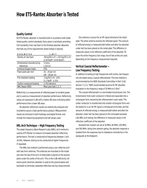
How ETS-Rantec <strong>Absorber</strong> is Tested<br />
Quality Control<br />
All ETS-Rantec absorber is manufactured in accordance with established<br />
quality control standards. Every piece is serialized, providing<br />
full tractability from raw foam to the finished absorber. <strong>Absorber</strong><br />
that fails any of the requirements shown below is rejected.<br />
P A R A M E T E R L I M I T<br />
Density of raw foam .48 kg/30.5 cm 3 +.023 kg/30.5 cm 3<br />
(1.05 lbs/ft 3 +0.05 lbs/ft 3 )<br />
Dimensional manufacturing 3 mm±<br />
tolerances<br />
(.125 in)<br />
Limiting Oxygen Index 25%<br />
Foam pores per inch<br />
16 – 24 per cm<br />
(40 – 60 per in)<br />
Fire retardant loading .5 kg/30.5 cm 3 ±5%<br />
(1.1 lbs/ft 3 ± 5%)<br />
Carbon compound loading ± 5% tolerance<br />
NRL Report 8093 Must pass tests 1, 2, 3<br />
Reflectivity is a measurement of reflected power to incident power<br />
and is used as a measurement of absorber performance. Reflectivity<br />
values are expressed in dB, with a higher dB value indicating better<br />
performance than a lower dB value.<br />
All absorber reflectivity results are statistically analyzed and<br />
recorded to assure a high-performance product. Measurement<br />
results are archived in both hardcopy and digital format, and<br />
include the measuring equipment and test setups used.<br />
NRL Arch Technique – High Frequency Testing<br />
The swept-frequency Naval Research Labs (NRL) arch method is<br />
used by ETS-Rantec to measure microwave absorber reflectivity<br />
performance. The test is conducted at frequencies between 1 and<br />
18 GHz. However, testing can be conducted at higher frequencies<br />
if requested.<br />
The NRL test method is performed using a non-reflective arch<br />
with two horn antennas. The antennas are mounted on the inside<br />
and near the top of the arch. A metal plate is placed on the ground<br />
plane under the center of the arch. This is the 0-dB reflectivity reference<br />
point. Anechoic absorber is used on the ground plane and<br />
backwalls to eliminate unwanted reflections during measurements.<br />
One antenna is source for an RF signal directed at the metal<br />
plate. The other antenna receives the reflected signal. The amount<br />
of reflected energy is measured both before and after the absorber<br />
under test has been placed on the metal plate. The difference in<br />
measured values is the reflection coefficient of the absorber. To<br />
cover the entire frequency test range, one of two arches are used,<br />
depending on the frequency measurement required.<br />
Vertical Coaxial Reflectometer –<br />
Low Frequency Testing<br />
In addition to testing at high frequencies with arches, low frequencies<br />
are tested using a coaxial reflectometer. This test method is<br />
recommended by the IEEE Standards Committee in Part 1128,<br />
Section 7.2.3.3,“IEEE recommended practice for RF absorber<br />
evaluation in the frequency range of 30 MHz to 5 GHz.”<br />
The coaxial reflectometer is a terminated transmission line. The<br />
transmission line’s outer conductor is flared and expanded into a<br />
rectangular form, becoming the reflectometer’s outer walls. The<br />
center conductor is transformed into smaller rectangular form and<br />
the dielectric is air. An RF signal is introduced at the feed, and the<br />
amount of reflected energy is measured both before and after the<br />
absorber under test has been placed on the removable backwall.<br />
Like NRL arch testing, the difference in measured values is the<br />
reflection coefficient of the absorber.<br />
Standard test markers are set at 30 MHz, 80 MHz, 250 MHz,<br />
and 500 MHz. Using time-domain gating, the absorber response is<br />
isolated from the responses due to impedance mismatches in the<br />
waveguide at the feedpoint.<br />
1 5 E T S – R A N T E C


