Introduction - Esprit Model
Introduction - Esprit Model
Introduction - Esprit Model

Create successful ePaper yourself
Turn your PDF publications into a flip-book with our unique Google optimized e-Paper software.
<strong>Introduction</strong><br />
Thank you for your purchase! This instruction manual will guide you<br />
through the installation and operation of your OSD Pro Expander TM<br />
(OSD Pro TM ).<br />
Please visit our support web page on http://www.eagletreesystems.com<br />
for the full color, electronic version of this manual, which may be<br />
updated if changes were made after printing. Please read the entire<br />
manual carefully before proceeding.<br />
If, after you read the manual, you have further questions or problems,<br />
visit our support web page for information on how to get answers to your<br />
questions, 24 hours a day.<br />
Packing List<br />
Your package should include the following: The OSD Pro Expander,<br />
five (5) male to male servo connectors, and a printed version of this<br />
manual.<br />
Instruction Manual for OSD Pro Expander TM<br />
Document Version 2.9<br />
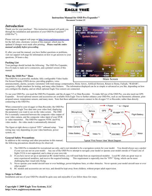
What the OSD Pro TM Does<br />
The OSD Pro is a powerful, modular, fully configurable Video/Audio<br />
Main Screen<br />
On-Screen Display (OSD) device, providing graphics, voice<br />
announcements, alarms, acoustic variometer with total energy compensation, Home Arrow, Artificial Horizon, Return to Home, Failsafe, “RADAR”,<br />
waypoints, a flight simulator for testing, and many other features. The information displayed can be as simple or advanced as you like, depending on how<br />
you configure the display, and on which optional Eagle Tree sensors are connected.<br />
To use your OSD Pro, you need the OSD Pro Expander, and the eLogger V3 or Data Recorder. To make full use of the OSD Pro, you also need our GPS<br />
Expander. Several optional sensors and accessories are available from Eagle Tree to further enhance your OSD Pro, such as our barometric altimeter, pitot<br />
airspeed sensor, temperature sensors, and many more. Note that these additional sensors connect to the eLogger V3 or Recorder, rather than directly<br />
connecting to the OSD Pro.<br />
When connected to your eLogger or Data Recorder, the OSD Pro<br />
superimposes Eagle Tree data onto your video feed, displaying<br />
the parameters you want to see on the video screen. The OSD<br />
Pro is normally connected between the composite video output of<br />
your video camera, and the composite video input of your DVR<br />
or video transmitter. The OSD Pro supports NTSC and PAL<br />
video modes – the video mode is automatically detected.<br />
The figure at right shows a typical “FPV” onboard setup. Your<br />
wiring may vary depending on your video hardware, power<br />
system, etc.<br />
General Safety Precautions<br />
In addition to the warnings and other precautions in this manual,<br />
the following precautions should always be observed:<br />
1) The OSD Pro is intended for recreational use only, and is not intended to be a navigation system for your model. You should always use a spotter<br />
if your eyes are not on your model. Any use of the OSD Pro to attempt to navigate your model or operate your model outside of Visual Line of<br />
Sight (VLS) is not supported, and is done at your own risk.<br />
2) If you have never set up or operated an RC model before, you will need help from an experienced modeler. Local RC clubs are great ways to<br />
meet experienced modelers, and receive the required training. This requirement is especially true for “FPV” flying, which can be more<br />
challenging than visual-only flying.<br />
3) Never operate your model aircraft near or over buildings, power/telephone lines, or other obstacles. Never operate your model aircraft near or over<br />
other people!<br />
4) RC models and accessories are not toys, and should be kept away from children, without proper adult supervision.<br />
Steps to Follow<br />
Installation and use of your OSD Pro should be quite easy and enjoyable if you follow these few steps:<br />
Copyright © 2009 Eagle Tree Systems, LLC<br />
http://www.eagletreesystems.com
Page 2<br />
1. First, read through the manuals for your eLogger V3 or Recorder, your GPS Expander, and any other Eagle Tree sensors, to familiarize yourself<br />
with the connection and function of these devices.<br />
2. Read through this manual to understand the warnings, determine the installation and setup sequence, etc., of the OSD Pro.<br />
3. Install or upgrade to the Windows Application and Firmware for your OSD Pro and Recorder as described in the “Windows Application and<br />
Firmware Update” section below.<br />
4. Configure your eLogger V3 or Recorder as described in the manuals for those, if you have not already done so. NOTE: It is recommended that<br />
you set the “Capture Rate” of your eLogger or Recorder to 10 samples/second, for best OSD Pro update rate and performance.<br />
5. Install and configure the OSD Pro as described below. Note that some features of the OSD Pro are configured with the Windows Application, and<br />
some features (ones that may change more often) are configured with the OSD Pro’s on-screen menus.<br />
6. Range test and enjoy!<br />
IMPORTANT: It is unlikely that the installation of the OSD Pro will affect your model’s radio range or control. But, as always after making an<br />
electronics change to your model, it is very important that you range and function test your model once the OSD Pro is installed to ensure that there is no<br />
impact on your system. Make sure that your “antenna down” operating range is within the manufacturer’s specifications. See your Radio owner’s manual<br />
for the correct procedure for your equipment. DO NOT OPERATE IF YOUR MODEL DOESN’T PASS THE ANTENNA DOWN RANGE CHECK<br />
Connecting your OSD Pro Hardware<br />
Connecting the OSD Pro TM to Your Camera and Video Recorder/Transmitter<br />
Two 3 pin servo connectors on the OSD Pro are used to route the composite video signal into and out of the OSD Pro. The input and output are compatible<br />
with standard 75 Ohm composite video equipment (either NTSC or PAL). See Figures 1 and 2 above, showing the top and bottom of the OSD Pro. The<br />
“Video Out” connection goes to your video transmitter (or DVR) and the “Video In” connection connects to the composite output of your camera. For both<br />
the video in and video out connections, the pin nearest the circuit board is Ground, the middle pin is Power, and the top pin is Signal. The Ground and<br />
Signal pins are the only ones used by the OSD PRO, but the Power pins are connected together internally in the OSD PRO, for your convenience. Note:<br />
Eagle Tree offers optional servo to RCA adapter cables, if needed.<br />
Using Audio with the OSD Pro TM<br />
If your Video Transmitter (or DVR) has an audio channel, connect the “Audio Out” pins of the OSD Pro to the audio input of your transmitter. The “Audio<br />
In” pins allow you to connect an external microphone to the OSD Pro, for hearing flight sounds. For both the audio in and audio out connections, the pin<br />
nearest the circuit board is Ground, the middle pin is Power, and the top pin is Signal. The Ground and Signal pins are the only ones used by the OSD<br />
PRO, but the Power pins are connected together internally in the OSD PRO, for your convenience. The OSD Pro supports “mic level” or “line level” audio<br />
input, and line level audio output. Never connect an amplified (speaker level) audio signal to the OSD Pro’s audio input!<br />
The OSD Pro’s built in voice announcements and the acoustic variometer sounds are sent via the audio output. If a microphone is connected to the OSD<br />
Pro, the microphone’s output is routed to the audio output when no announcements are being made. When it is time for a voice announcement, or the<br />
variometer is sounding, the audio output is automatically switched. See the PC Configuration and onscreen menu information below for configuring the<br />
audio options.<br />
Connecting the OSD Pro TM to your <strong>Model</strong>’s Radio Receiver for Menu Setup and Configuration<br />
IMPORTANT: never connect receiver channels to the OSD Pro if your Receiver is powered by more than 15 volts!<br />
Two receiver input channels (Aux1/Up-Down and Aux2/Select) are required to configure the OSD Pro via the on-screen menus. Only one receiver channel<br />
(Aux1) needs to be dedicated to the OSD Pro. The other receiver channel, Aux2, can be shared between the OSD Pro and with other features of your<br />
model, under certain circumstances. See the “On Screen Menu Configuration” section below for more information on how the Aux1 and Aux2 channels are<br />
used.<br />
While it is not necessary to leave Aux1 and Aux2 connected to your receiver after on-screen configuration, it is much more convenient. Many of the<br />
advanced features of the OSD Pro are configurable via the menus, and the RTH feature generally requires in-flight testing and configuration, via the menus.<br />
IMPORTANT: never operate your model with only one of the Aux1 or Aux2 channels connected! Either connect both, or neither.<br />
The Aux1 and Aux2 channels are connected to your receiver via two of the male to male servo connectors. The “Futaba” end of each connector plugs into<br />
the OSD Pro, and the “Universal/JR” end plugs into your receiver. Note that the Futaba plug enforces correct polarity when connected to the OSD Pro.<br />
Ideally, both the Aux1 and Aux2 are connected to two toggle switches on your radio, such as the “Gear” or “Aux” toggle switches. But, rotary switches will<br />
also work fine, when rotated near their extents.<br />
Copyright © 2009 Eagle Tree Systems, LLC<br />
http://www.eagletreesystems.com
Page 3<br />
Note that the OSD Pro will generally ignore the Aux2 channel input unless the Aux1 channel is manipulated to enter menu mode, as described in the Menus<br />
section of the manual. So, you can leave the OSD Pro connected to the two channels, and Aux2 movement will not affect the OSD Pro unless you<br />
manipulate the Aux1 channel first, to enter menu mode. The only exception is if you have defined multiple main screen pages. In this case, Aux2 will<br />
switch between the pages, when toggled outside of menu mode.<br />
If you do need to change OSD settings in flight, you would need to be able to manipulate Aux2 channel after manipulating the Aux1 channel to enter menu<br />
mode. If one of your radio channels can be manipulated with only marginal effect on flight (perhaps camera pan or tilt), that channel could be shared with<br />
the OSD Pro’s Aux2 input.<br />
Note that the OSD Pro may take a small amount of power (up to approximately 200 mA of current) from the receiver. This amount is typically very small<br />
compared to the amount of power even a single small servo can consume. The OSD Pro also takes power from its connection to the eLogger or Recorder. It<br />
senses which power source has a higher voltage, and uses that power source. The eLogger supplies 5V to the OSD Pro.<br />
Connecting the OSD Pro TM to your <strong>Model</strong>’s Control Surfaces for Return to Home/Failsafe operation (Advanced)<br />
If you intend to use the Return to Home or Failsafe features of the OSD Pro, your throttle, elevator, and aileron/rudder servos connect to the outputs of the<br />
OSD Pro, as shown in Figure 1. See the “Safety Mode Overview” section below for more information. We recommend connecting your ailerons to the<br />
Aileron/Rudder connection instead of the rudder, if your plane has both ailerons and rudder.<br />
Note that “flying wing” models which use elevon or vtail mixing are supported. The elevator and aileron/rudder servo inputs and outputs are used for the<br />
left and right channels, in these modes. Please see the Safety Mode section for details.<br />
The aileron/rudder, elevator and throttle inputs to the OSD Pro (shown in Figure 2) are connected to their respective outputs of your radio receiver, using 3<br />
of the included male to male servo connectors. For all of the OSD Pro servo inputs and outputs, the pins closest to the circuit board are ground, the middle<br />
pins are power, and the top pins are signal. Note that when the Futaba TM end of the included male to male connects is connected to the OSD Pro,<br />
polarization is enforced.<br />
When connected as described above, the servos receive power from the radio receiver, just as if they were connected directly to the receiver. The input and<br />
output servo power pins of the OSD Pro connect to each other internally.<br />
NOTE: the servo connections described above are not necessary if you do not wish to use the safety features.<br />
Using the OSD Pro TM with Stabilization Systems, such as the FMA TM Co-pilot TM<br />
If you plan to use Return to Home feature with a stabilization system, please see the “Stabilization System Connection” section in the Safety Mode portion<br />
of the manual.<br />
Connecting the OSD Pro TM to your eLogger or Data Recorder<br />
eLogger V3<br />
The four pin wire with black connector on the OSD Pro plugs into the “LCD/TX” port of your eLogger V3, as<br />
shown in Figure 3. If you have a PowerPanel or other sensors, those can “daisy chain” to the pins on the OSD<br />
Pro, with the polarity as indicated on the OSD Pro label, as shown in Figure 2.<br />
IMPORTANT: when using the OSD Pro Expander with the eLogger V3 and the GPS Expander, and you do not<br />
plan on connecting any outputs of your receiver to the OSD Pro, a maximum voltage of approximately 8 volts<br />
(2s LiPo pack) should be used to power the eLogger. If you are using a pack greater than 8 volts, the eLogger’s<br />
internal regulator may temporarily shut down, which will cause the OSD Expander to turn off, resulting in no<br />
video display. To avoid this issue, use our “Battery Backup Harness” which can connect to a spare 5V to 6V<br />
BEC or spare receiver channel when using larger battery packs. Note that if you connect receiver outputs to your OSD Pro, the OSD Pro receives backup<br />
power from the receiver, so the Battery Backup Harness should not be needed, even with battery packs larger than 4s.<br />
Data Recorder<br />
The four pin wire with black connector on the OSD Pro plugs into the “FCC TX” port of your Data Recorder as<br />
shown in Figure 4. Make sure that you connect it in the correct location on the recorder, and with the correct<br />
polarity! IMPORTANT: if you do not plan on connecting a Seagull transmitter to the 4 pin male<br />
connection of the OSD Pro, make sure you cover the exposed 4 pin connector with tape, or otherwise<br />
keep it from shorting to other metal objects. Touching the exposed 4 pin connector to other metal<br />
objects will damage the recorder when it is powered!<br />
Windows Application and Firmware Update<br />
To use the OSD Pro TM , you must update to Eagle Tree Windows Application version 7.40 or higher. To<br />
update, download the latest application from the support page of our website, located at<br />
http://eagletreesystems.com/Support/apps.htm. After connecting the OSD Pro to the eLogger/Recorder, and<br />
downloading and installing the latest Windows Application, the firmware of both your eLogger/Recorder and the OSD Pro will need to be updated. To<br />
upgrade your firmware, just click “Hardware, Firmware Control” and first click the “Update” button for the eLogger/Recorder, and repeat this process to<br />
update the firmware for the OSD Pro.<br />
Note: as new features and bug fixes become available to the OSD Pro, the changes can be downloaded from our website. Please check our website<br />
periodically for new software versions.<br />
Copyright © 2009 Eagle Tree Systems, LLC<br />
http://www.eagletreesystems.com
Configuring the OSD Pro TM with the Windows Application<br />
Some of the features of the OSD Pro are configured with the Windows Application. After updating the Windows application, and updating the firmware,<br />
click “Hardware, Choose Parameters to Display on Video OSD” to configure the OSD Pro.<br />
If the hardware is connected correctly, the Video OSD Setup Utility screen (the setup screen) shown in Figure 5 should appear. If it does not appear, and an<br />
error messages appears instead, please see the troubleshooting section of this manual.<br />
Configuring Parameters to Display on the Video OSD<br />
The OSD Pro main screen, as shown in the Main Screen figure, supports two rows of user configurable text based data parameters along the top of the<br />
screen, and two rows of parameters near the bottom of the screen. Each row can have up to 5 parameters, for a total of 20 parameters. NOTE: parameters<br />
are easiest to read if they are positioned with (at most) 3 parameters per line, as shown in Figure 5.<br />
The setup screen’s green simulated display corresponds to the rows and colums of these four lines of parameters. To configure a parameter to display, click<br />
“Choose the next Parameter to Configure.” This dropdown menu lets you choose a parameter to display on the OSD screen. The available parameters depend<br />
on your Recorder type, and the sensors you have installed.<br />
The OSD Pro can have more than one “page” of parameters defined for<br />
the main screen. So, virtually infinite configuration is possible. The<br />
current page being configured is indicated by the “OSD Page: 1” text<br />
below the simulated display. Use the left and right arrows below the<br />
dropdown menu to switch between OSD Pages on the simulated<br />
display.<br />
NOTE: If more than one OSD Pro display page has been configured,<br />
toggling your radio’s Aux2/Select switch (if configured) when not in<br />
menu mode will cause the display page to advance to the next page.<br />
Also, an option for timed switching between main screen pages is<br />
described in the on-screen menus section below.<br />
Once a parameter is selected from the dropdown menu, it will appear at<br />
the next available location on the simulated display. To change the<br />
location on the page for displaying the parameter, just click the location<br />
with your mouse, and drag the parameter to the desired location.<br />
If there is a parameter that you would like to display on ALL your OSD<br />
Pro main pages, click on the parameter on the simulated display, and<br />
click the “Display on all pages” checkbox. Note that this has no effect<br />
if you have defined only one main page.<br />
The text field labeled “Enter OSD Screen Name for the Parameter”<br />
indicates the 3 digit label that will be displayed beside this<br />
parameter on the OSD. You can change this 3 digit label to be whatever<br />
you want.<br />
If for some reason you wish to clear all the parameters you have<br />
programmed, click “Reset Parmeters” and configure them again.<br />
Page 4<br />
Voice Announcement of Parameters<br />
A powerful feature of the OSD Pro is its ability to speak the status of<br />
selected parameters to you, so you don’t have to look at numbers on the screen as much.<br />
Figure 5<br />
Both male and female voices are provided (presently only in English). Choose this option with “Select Voice.”<br />
To configure a parameter for periodic announcement, highlight the parameter on the simulated display, and check the “Announce this value every X seconds”<br />
box. Then, choose the period for announcement. And, if you desire to hear the units spoken for all spoken parameters, check the “Speak Units” box.<br />
For example, if you configured altitude to be spoken every 30 seconds, and click the Speak Units option, the OSD Pro will speak “Altitude XYZ Meters”<br />
every 30 seconds (assuming your system is configured for Metric).<br />
Note that if you desire to have a parameter spoken only, but not displayed on the main screen, simply place the parameter to be displayed on a page that you<br />
don’t plan on using. For example, if you have your parameters on page 1, and you wish to have Altitude periodically spoken, but not displayed on page one,<br />
place Altitude on Page 2.<br />
Setting Alarms for Parameters<br />
The OSD Pro setup screen makes it easy for you to set up High or Low trigger threshold alarms for the parameters you have configured. These alarms can<br />
be used to alert you of potential problems, before they become serious.<br />
There are 3 ways that the OSD Pro can alert you if a parameter has reached its trigger level:<br />
1) The parameter is displayed in “reverse video” on the screen, with an exclamation point “!” beside it.<br />
Copyright © 2009 Eagle Tree Systems, LLC<br />
http://www.eagletreesystems.com
Page 5<br />
2) Optionally, the parameter can be spoken when an alarm for it is triggered. This will happen whether or not you have configured periodic<br />
announcements of that parameter. A “beep” is played before the alarm is spoken, allowing you to differentiate a spoken alarm from a periodic<br />
announcement.<br />
3) If the OSD display is turned off via the on-screen menus, you can configure the OSD display automatically turn on when a particular alarm is<br />
triggered.<br />
4) If you have multiple display pages defined, you can have the OSD Pro automatically return to the page which contains the parameter that has<br />
triggered the alarm.<br />
For example, if you want to configure a low voltage alarm of 10 volts, and want the OSD Pro display to remain turned OFF until a voltage lower than 10<br />
volts is detected, and you want the parameter spoken when the alarm occurs, you would do the following:<br />
1) Add the “Voltage” parameter to the simulated display.<br />
2) With the Voltage parameter highlighted on the simulated display, click “Low Alarm Enabled” and enter “10.0” for the alarm trigger value.<br />
3) Click the “Turn on the OSD Pro when alarm is triggered.” option.<br />
4) Click the “Check here to automatically Switch to this Parameter’s OSD Pro page when alarm is triggered” option (assuming you have configured<br />
more than one page)<br />
5) Click the “Speak This Alarm” option.<br />
Then, while you are operating your vehicle, the OSD Pro display can be turned off with the on-screen menus, and will turn itself back on, display the voltage<br />
in reverse video, and speak “ Pack Voltage 9.9 Volts” when a voltage less than 10 volts is detected.<br />
NOTE: If two or more alarm conditions occur simultaneously, only the last occurring condition will be signaled.<br />
If the last condition to trigger an alarm goes away, the next active alarm condition will be signaled, etc.<br />
Programming GPS Waypoints<br />
Note: See the Waypoints section below for more information on using Waypoints. To program a waypoint, enter the latitude and longitude in the “GPS<br />
Waypoints” section of the setup screen, and then click “Next.” That waypoint is then saved, and you can enter the location of the next waypoint. Also,<br />
once waypoints are defined, they can be edited by selecting them with the Next button. The “Delete All Waypoints” button clears the waypoints you have<br />
entered.<br />
Configuring On-Screen Menu Parameters<br />
Click the “Configure On-Screen Menu Parameters” if you would prefer to use the Windows application to adjust the settings normally adjusted with the onscreen<br />
menu. Note: the on-screen wizards cannot be completed with the Windows application.<br />
Completing the Windows Setup<br />
Once you have defined your desired parameters, alarms, and waypoints, click the OK button to download the settings to the OSD Pro. Note that the first<br />
time you download settings after updating the Windows software, or whenever you switch between Male and Female voice, the download of the settings will<br />
take much longer than normal (about 30-55 seconds). Normally, the download time is less than 10 seconds.<br />
Operating your OSD Pro<br />
After connecting and configuring your OSD Pro as described above, you should see the main<br />
OSD Pro screen on your video receiver, as shown in the Main Screen figure. Before the main<br />
screen appears, the startup screen, as shown in Figure 7, should appear for about 3-5 seconds. If<br />
the startup screen remains for more than this length of time, or no OSD information appears at<br />
all, please see the troubleshooting section.<br />
“RADAR” Feature<br />
The RADAR feature is an intuitive feature which makes it easier to keep track of your model’s<br />
location relative to home, and the direction of your model’s travel relative to the direction the<br />
pilot is facing. See the Main Screen figure. The circular indicator in the center of the screen<br />
marks the takeoff point, in a "bird's eye" view map. The RADAR location and direction of travel<br />
indicator (the chevron) indicates where you are in relation to home. The up direction is<br />
configurable in the on-screen menus described below.<br />
Figure 7<br />
As your model moves relative to home, the chevron moves relative to the center of the screen.<br />
Also, the direction the chevron is pointing indicates the direction the model is traveling, relative to home. So, if your model is flying toward home, the<br />
chevron will point toward home, regardless of where it is on the display screen. The RADAR feature is the ultimate way to keep tabs on where you are<br />
relative to home, as an aid to piloting.<br />
Artificial Horizon Display<br />
When you connect the FMA Direct CPD-4 X/Y horizon sensor (either with our without the FMA stabilization Computer), an artifical horizon line can<br />
be displayed on the video screen.<br />
Information on how to connect the FMA Direct sensor to the OSD Pro system, and configure the Artifical Horizon display, can be found in this document:<br />
http://www.eagletreesystems.com/support/manuals/FMA-OSD-Pro.pdf<br />
Waypoints<br />
Copyright © 2009 Eagle Tree Systems, LLC<br />
http://www.eagletreesystems.com
Page 6<br />
The OSD Pro includes a powerful, graphical display of up to 3 waypoints, on the main screen, as shown in the Main Screen figure. These are displayed<br />
relative to the “Home” position, similar to the RADAR feature described above. When the OSD Pro is initialized, the first waypoint you entered is the<br />
active waypoint (circled), and the “Distance to Waypoint” parameter (if you chose to display it) indicates the distance to the first waypoint. As each<br />
waypoint is reached, the next defined waypoint becomes the active waypoint (it becomes circled), and the Waypoint Distance indicates the distance to the<br />
next waypoint. After all the defined waypoints have been reached, the waypoint order reverses, and the next to last waypoint becomes the active waypoint.<br />
NOTE: the OSD Pro will not autonomously fly to waypoints, and the waypoints must be within Visual Line of Sight (VLS) of “Home”. VLS is defined as<br />
5280 feet (1609 meters). So, care must be taken to ensure that you don’t configure waypoints farther than the VLS distance from the location you turn your<br />
model on. Waypoints farther away than VLS will not appear on the main screen, and an error message will appear.<br />
Flight Simulator<br />
The OSD Pro’s built in flight simulator simplifies testing the Return to Home feature, as well as testing alarms, voice prompts, and other features. See the<br />
RTH Testing/Adjustment Procedures section for information on using the simulator. The simulator supports both traditional, fixed wing aircraft, and vtail<br />
or elevon controlled aircraft. NOTE: the simulator’s implementation is simplistic. It is not a full simulator based on the laws of physics. So, your model’s<br />
operation in the air could be quite different than the characteristics observed in the simulator!<br />
Configuring the OSD Pro TM with the On-Screen Menus<br />
A powerful, intuitive set of menus are provided with the OSD Pro, for configuration at home, in the field, or even in flight.<br />
To invoke the menus and change menu parameters, the Aux1 (Up/Down) and Aux2 (Select) radio channels are used. These are connected as described in<br />
the configuration section above.<br />
To invoke menu mode, click the Up/Down channel up. Note: “up” may be “down” depending on how your control channels are configured on your radio.<br />
After clicking, the main menu should appear, as shown in Figure 8. Once you are in menu mode, the Up/Down button is used to highlight the parameter to<br />
be changed. The “>” menu cursor to the left of the menu items indicates which item is currently highlighted. Moving the Up/Down button in either<br />
direction causes the next menu item to be highlighted.<br />
To modify the highlighted menu item, clicking down on the Select channel invokes edit mode for that<br />
item. Edit mode is indicated by an up or down arrow to the right of the highlighted item (the<br />
direction arrow). Now, when you move the Up/Down switch up or down rapidly, the item’s value<br />
will be either incremented or decremented, depending on whether the direction arrow is point up or<br />
down. This method of entry allows you to quickly increase or decrease an item’s value, since each up<br />
and each down movement of the Up/Down switch will change the item.<br />
To change the direction arrow from up to down, move the Up/Down switch DOWN, and leave it<br />
down for more than one second. Then, the direction arrow will point down, rapidly toggling the<br />
Up/Down switch will decrease the item’s value. Conversely, to point the direction arrow up, leave<br />
the Up/Down switch in the UP position for more than one second.<br />
Figure 8<br />
Note: all the on-screen menu settings (except the wizards) can also be configured with the Windows application, as described in the Windows application<br />
information above.<br />
Description of On-screen Menus<br />
Main Menu<br />
The Main Menu is shown in Figure 8, with the following settings:<br />
• Test Return to Home: see the Safety Mode section below for more information<br />
• Turn OSD Display ON or OFF: turns the main screen on or off. When off, no OSD information is visible, but alarms can be programmed to turn<br />
the main screen back on. Also, voice announcements are still enabled when the main screen is off.<br />
• Configure Safety Mode: Launches the Safety Mode Configuration menu, described below.<br />
• Configure OSD Display: Launches the OSD Display configuration menu, described below.<br />
• Configure Audio: Launches the Audio Configuration menu, described below.<br />
• Display Live or Max Values?: Determines whether live or maximum values are displayed on the main screen. If Max is selected, the maximum<br />
values (minimum voltage) encountered since the OSD Pro was powered are displayed. There is an up arrow (or down arrow for voltage) displayed<br />
to the left of the parameters, indicating they are the Maximum (Minimum) values. The maximum values of some parameters are not available,<br />
which is indicated by an “*” for the value of that parameter.<br />
• Set Battery milliamp-Hours: Sets the mAH capacity of your battery pack. This parameter, along with the eLogger’s current sensor, is used to<br />
display the graphical battery level. Warning: batteries often have less than their stated mAH capacity when drained at high rates.<br />
• GPS, RADAR and Waypoint Settings: Launches the GPS/RADAR/Waypoint configuration menu.<br />
• Configure Variometer: Launches the Variometer configuration menu.<br />
• Configure Artificial Horizon: Launches the Artificial Horizon configuration menu<br />
• Jump to Exit after change?: If this is set to YES, the menu cursor will jump to “Exit Menu” after a menu item is changed. If it’s set to NO, the<br />
menu cursor advances to the next menu item.<br />
• Flight Sim (Disable Motor!): See the “Flight Simulator” section below.<br />
• Exit Menu: Returns to the main screen (Exits Menu Mode) when selected<br />
Copyright © 2009 Eagle Tree Systems, LLC<br />
http://www.eagletreesystems.com
Safety Mode Menu<br />
Page 7<br />
NOTE: carefully read the Safety Mode Overview section before changing these settings!<br />
• Run Safety Mode Wizard: This invokes the safety mode configuration wizard, described below.<br />
• Reset Cruise Stick Positions: Recaptures the model’s aileron/rudder, elevator, and throttle settings for level flight. These settings are captured<br />
during the Safety Mode wizard, but sometimes these need to be recaptured, if you have retrimmed your plane.<br />
• Select Desired Safety Mode: Selects one of the safety mode options. None: no safety mode enabled. Failsafe: selects the failsafe mode. Rtrn<br />
Home: selects the Return to Home safety mode.<br />
• Choose <strong>Model</strong> Control Type: Selects the type of control surfaces you use on your model. For “traditional” fixed wing models, which use<br />
ailerons/rudder and elevator, choose “Standard.” For models that use elevon or vtail mixing, such as “flying wings” choose “Elevon.”<br />
• Choose Receiver Type: Sets the type of Radio/Receiver you are using. There are two options. PPM/No FS: this option should be chosen if your<br />
receiver stops controlling the servos if you turn off your radio (or the servos start moving randomly). PCM/FS: this option should be chosen if<br />
your receiver holds the last servo position (or goes into a failsafe position) when the radio is turned off. Most, but not all, 2.4GHz radios (such as<br />
Spektrum TM and Futaba TM 2.4GHz radios) are PCM. If you are unsure of the mode, turn off your radio, and gently move one of the servo arms<br />
while the receiver is still powered. If the servo moves without resistance and stays in the new position, or your servos start moving randomly, select<br />
“PPM/No FS” receiver mode. Otherwise, choose the “PCM/FS” mode.<br />
• Number Failsafe Chans on RX: If your radio does not have any failsafe channels programmed, set this to “No FS Chs.” If your receiver only<br />
supports throttle failsafe, and you have programmed a throttle failsafe position with your radio, select “1 FS Chns.” If your radio supports failsafe<br />
positions on your elevator, aileron/rudder, and throttle channels, and you have programmed failsafe positions on all of these, choose “3+ FS Chns.”<br />
• Cruise Speed: This parameter sets the desired (optimal) cruise speed of your model. Set this parameter to the approximate speed at which your<br />
model maintains level flight (either MPH or K/H, depending on units). This should be the speed of the model for it to maintain level flight. Note<br />
that when you run the Safety Mode Wizard, and are prompted to set throttle for Cruise Speed, you should adjust your throttle stick position so that it<br />
sets a speed at which the model maintains level flight, assuming no turns are being made. So, your throttle setting during the Safety Mode Wizard<br />
should result in the approximate speed that you enter here for Cruise Speed.<br />
• Cruise Altitude (300/120): Set this parameter to the desired altitude which the Return to Home feature should attempt to maintain. If there are<br />
obstacles between your model and home that have higher elevation than this setting, the model may crash into them, so consider this in your setting.<br />
Of course, never set this value above the legal flying limit for your area. This setting is in Feet if you have configured your system for English units,<br />
or in meters if you are configured for Metric units. The default values for (English, Metric) are show in the menu item in parentheses.<br />
• Altitude Error(100/40): This setting has two purposes. First, this setting controls the tolerable window of altitude above and below the Cruise<br />
Altitude setting, referred to as the “Cruise Altitude Window.” For example, if Cruise Altitude is set to 300, and Altitude Error was set to 100, the<br />
Cruise Altitude Window would be between 200 and 400. Never set this value so that this value, when added to “Cruise Altitude” parameter above,<br />
exceeds the legal flying limit for your area. Secondly, this setting is also used as the limit to the input of the pitch PID controller. See below.<br />
The default values for (English, Metric) are show in the menu item in parentheses.<br />
• Pitch Proportional Gain (50): This setting adjusts the proportional input to the elevator PID controller. The default value is shown in<br />
parentheses. The elevator PID controller examines the difference between the present altitude, and the desired Cruise Altitude. If the difference is<br />
greater than the Altitude Error setting above, the difference is limited to Altitude Error. Then, the elevator controller multiplies this difference by<br />
the Pitch Proportional Gain value.<br />
• Pitch Derivative Gain (50): This setting adjusts the derivative input to the elevator PID controller. Higher values of this setting damp (reduce)<br />
the climbrate. The effect of this parameter is increased as the Cruise altitude is approached, which reduces overshoot. Increase this parameter if<br />
the model “porpoises” between too high and too low, during testing. Decrease the value if the model stops climbing too soon or too abruptly.<br />
• Turn Proportional Limit (20): this setting controls the maximum error that the heading controller will accept as an input. The heading<br />
controller examines the present heading, and the heading for home. If the difference in these headings is greater than Turn Proportional Limit, the<br />
Turn Proportional Limit value is used instead. The default value is shown in parentheses.<br />
• Turn Proportional Gain (50): This setting amplifies the proportional input to heading controller. The default value is shown in parentheses.<br />
The heading controller determines the present heading, and the desired heading for home. The difference in headings (limited by Turn<br />
Proportional Limit as described above) is then multiplied by Turn Proportional Gain.<br />
• Turn Derivative Gain (50): This setting adjusts the derivative input to the heading PID controller. Higher values of this setting damp (reduce)<br />
the rate of turn. The effect of this parameter is increased as the correct home heading is approached, which reduces overshoot. Increase the value<br />
of this parameter if the plane continues to turn after reaching the correct home heading. Decrease the value if the model stops turning too soon, or<br />
stops turning too abruptly.<br />
• Turn Integral Gain (50): This setting controls the integral input to the heading PID controller. The heading PID controller examines how long it<br />
is taking to turn to the correct home heading. As time passes during the turn, the aileron/rudder is turned more and more, to increase the rate of turn<br />
over time. Normally the impact of the integral gain should be small. But, if a strong wind or other factor is keeping the plane from reaching home<br />
in a reasonable amount of time, integral gain will continue to increase the turn rate.<br />
Copyright © 2009 Eagle Tree Systems, LLC<br />
http://www.eagletreesystems.com
Safety Mode Wizard<br />
Before running the Safety Mode wizard, ensure your model’s motor is disconnected or otherwise disabled. NOTE: only run the Safety Mode<br />
Wizard when your model is on the ground! Each screen of the safety mode wizard requiring you to make an adjustment to your radio is timed, and<br />
remains on the screen for approximately 10 seconds. Ensure that you have completed the adjustment before the timer counts to 0, and make sure that<br />
you hold the adjustment until the next screen appears. If you make a mistake during the Safety Mode wizard, just run it again later.<br />
• Read RTH Manual/Click SELECT: Ensure that you have fully read this manual, and then click the Aux2/Select switch.<br />
• DISCONNECT MOTOR / Click SELECT: Ensure that you have disconnected your motor, and click the Aux2/Select switch.<br />
• Set Sticks for level flight: Set your aileron/rudder, elevator, and throttle stick positions where you typically set them for level flight, and hold<br />
them there until the next screen appears. Note that if you are using Failsafe Safety Mode, the aileron/rudder and elevator positions you choose in<br />
this step become the positions the OSD Pro will use for failsafe mode.<br />
• Turn Transmitter off now: Turn your transmitter off, and leave it off until the next screen appears.<br />
• Turn Transmitter back on now: Turn your transmitter back on.<br />
• Mov Rudder/Aileron Stick Left: Move your Rudder/Aileron stick to the position you use for making a normal left turn. Don’t give more left<br />
stick than you would do normally during flight! The OSD Pro’s RTH function will never exceed this the rudder/aileron left turn position, or the<br />
corresponding right turn position, when it attempts to steer the model. So, the amount of left stick you supply will set the maximum throw of the<br />
aileron/rudder during RTH. NOTE: during this step, the OSD Pro also examines the elevator position. If your radio is programmed for elevator<br />
aileron mixing, it will be detected during this step, and a proportional amount of up elevator will be applied during RTH turns. If your radio does<br />
not do this mixing, but you desire RTH to provide up elevator when turning, move your elevator stick to the desired amount of climb<br />
(corresponding to full Aileron/rudder stick left) during this step.<br />
• Mov Elev TX STICK Down(Climb): Move the Elevator stick downwardly, to the position you would use for normal climb. Don’t give more<br />
down stick (climb) than you would do normally during flight! Note that this step results in up-elevator. The OSD Pro’s RTH function will<br />
never exceed this elevator up position, or the corresponding elevator down position, when it attempts to climb or descend the model. So, the<br />
amount of down stick you supply will set the maximum throw of the elevator during RTH.<br />
• Set Throttle for Motor Off: Set the Throttle stick to the position which turns off the motor. Note that if you are using Failsafe Safety Mode, the<br />
throttle position you choose in this step becomes the position the OSD Pro will use for the throttle when in failsafe mode. IMPORTANT: note<br />
that if RTH is invoked, and the GPS signal is not adequate, the OSD Pro will set your throttle to this position. Therefore, if your model is<br />
on the ground, and you turn off your transmitter or test RTH, your throttle could be put in the Motor Off position. If full motor off is not<br />
chosen for the Motor Off position, your motor will start!<br />
• Set Throttle for Climbing: Set the Throttle stick to the position you would normally use for climbing the model.<br />
• Wizard complete. Click SELECT: This is the last page of the wizard. Click the Aux2/Select switch to return to the Safety Configuration Menu.<br />
GPS and Waypoint Settings Menu<br />
This menu page lets you configure GPS and waypoint settings.<br />
• Display Lat-Lon Position: This item lets you choose when latitude/longitude position is displayed on the main screen. The choices are:<br />
o Never: position is never displayed<br />
o Trouble: position is displayed when the RTH or Failsafe safety modes are invoked, or if an alarm has been triggered<br />
o Low Alt: position is displayed for Trouble, and additionally if the model’s altitude is less than the setting you made in the<br />
“Cruise Altitude” item in the Configure Safety Mode menu<br />
o Distance: position is displayed for Trouble, Low Alt, and additionally if the distance of the model from home exceeds the Maximum<br />
“RADAR Radius” item in the Configure OSD Display menu.<br />
o Always: position information is always displayed<br />
• Enable RADAR Display: Select YES to enable the RADAR feature, described earlier in the manual.<br />
• RADAR Up Direction (Degrees): This parameter sets the UP direction of the RADAR feature. For example, if you fly your model so that your<br />
body is facing 15 degrees N, you would set this to 15. This results in the RADAR icon flying up on the OSD Pro main screen when you are flying<br />
the model in the direction you are facing. Normally, the runway is perpendicular to the direction you are facing.<br />
• Set RADAR Maximum Radius: This sets the maximum radius for the RADAR and Waypoint display. Set this to the maximum distance away<br />
from home that you typically fly. For example, if you normally fly a maximum of 5000 feet away from home in any direction, set this to 5000. If<br />
your model exceeds this distance, the RADAR icon will change from normal video to reverse video, to indicate you are out of range. Likewise, if<br />
you have defined waypoints that exceed this maximum radius, they will be displayed in reverse video.<br />
• Show Waypoints on RADAR: Set this to YES if you want to display the waypoints you entered in the Windows Setup Utility on the main<br />
display screen.<br />
• Set Minimum Satellite Count: Set this to a non-zero value if you wish to specify the minimum number of satellites that must be in view, before<br />
the Home location and altitude are finalized. This setting is useful if you find that, in your area, the GPS module initially reports somewhat<br />
invalid altitude or position information until a certain number of satellites are in view.<br />
• Require 3D GPS Fix: Set this to YES if you wish to wait until a 3D GPS fix is attained, before the Home location and altitude are finalized. If<br />
you are using GPS altitude rather than a barometric altitude sensor, this generally should be set to YES, as GPS altitude will not usually be accurate<br />
unless a 3D fix is attained.<br />
• Set Maximum HDOP: Horizontal Dilution of Precision (HDOP) is a measure of the GPS Expander’s fix quality. The lower this number, the<br />
better the fix. The HDOP can vary with a variety of factors, including the position of the satellites in view relative to each other. As a very<br />
general rule, HDOP less than 2.0 is highly desirable. HDOP less than 1.3 is desirable, but may not always be attainable. The default value of 9.9<br />
essentially turns this check off. If you wish for a certain quality of fix to be attained before the Home location and altitude are finalized, set this to<br />
a value lower than 9.9.<br />
• Distance to Pilot as LOS?: Set this to YES if you want the Line of Sight distance (computed using altitude as well as ground distance) displayed<br />
with the Distance To Pilot display. Set it to NO if you want the ground distance.<br />
• Seconds to Wait post GPS Fix: Set this to a non-zero value if you wish to specify the number of seconds that must elapse after the GPS acquires<br />
its first fix, before the Home location and altitude are finalized.<br />
Copyright © 2009 Eagle Tree Systems, LLC<br />
http://www.eagletreesystems.com<br />
Page 8
Page 9<br />
Configure OSD Display Menu<br />
These menu items set options for OSD Display features.<br />
• Set Page Switch time (secs): If you have configured multiple pages of data parameters using the Windows Setup Utility, and wish to switch<br />
between the pages of data every few seconds, set this parameter to the number of seconds between page switches. NOTE: In addition to this<br />
option, toggling your radio’s Aux2/Select switch (if configured) when not in menu mode will cause the display page to advance to the next page.<br />
• Show Airspeed Ladder: Set this to YES if you would like to display the speed ladder on the main screen. The speed ladder ranges from 0 to 999,<br />
and displays in either MPH, or K/H, depending on your chosen units.<br />
• Show Altitude Ladder: Set this to YES if you would like to display the altitude ladder on the main screen. The Altitude ladder ranges from -999<br />
to 9999, and displays in either feet or meters, depending on your chosen units.<br />
• Show Graphical Compass: Set this to YES if you would like to display the graphical compass on the main screen.<br />
• Show Crosshairs: Set this to YES if you would like to display the crosshairs in the center of the screen.<br />
• Show Graphical Battery: Set this to YES if you would like to display the graphical battery on the main screen. Don’t forget to set your<br />
battery’s mAH capacity on the Main Menu screen also.<br />
• Set Horizontal Screen Shift: This setting lets you adjust the horizontal position of the OSD data on your video screen. Increasing this parameter<br />
causes the OSD data to shift rightward on the screen.<br />
• Set Vertical Screen Shift: This setting lets you adjust the vertical position of the OSD data on your video screen. Increasing this parameter causes<br />
the OSD data to shift downwardly on the screen.<br />
• Narrow Screen (see manual): This setting compresses the OSD screen horizontally, decreasing the width. It does not affect the video width. Try<br />
this option if your DVR or display does not let you see all of the OSD data, even after adjusting the horizontal screen shift. NOTE: If you select<br />
this option, and find that your OSD Pro is suddenly has display issues, email support@eagletreesystems.com.<br />
• On/Off Display with Aux2?: Set this to YES if you would like to turn the main display screen on and off, by toggling the Aux2 switch. Note that<br />
using this option would likely require the Aux2 channel to be dedicated to the OSD Pro, and not shared with other equipment.<br />
• Set OSD Text White Level: Adjusts the white level of the OSD Pro text and graphics. Normally, this does not need to be changed from the default<br />
setting of “7.”<br />
• Set OSD Text Black Level: Adjusts the black level of the OSD Pro text and graphics. Normally, this does not need to be changed from the default<br />
setting of “0.”<br />
• Enable EagleEyes Telemetry: This feature enables embedding of digital telemetry data for our EagleEyes TM FPV Ground Station. See our website<br />
for more information.<br />
• Display Servo Deflections: This display option can assist in fine-tuning RTH and other settings. It displays the present Aileron/Rudder, Elevator<br />
and Throttle servo offsets. The offsets range from extremes of approximately -2000 to 2000. Zero corresponds to the neutral stick settings that<br />
you indicated in the “Set Sticks for Level Flight” screen of the Safety Mode Wizard<br />
Configure Sensors and Units<br />
The Configure Sensors and Units menu has the following items:<br />
• Use Baro Alt for RTH/Ladder: Set this item to YES only if you have a barometric altimeter (either the Altimeter Microsensor, or a Flight Data<br />
Recorder). When set to YES, the barometric altimeter will be used for the altitude ladder, the acoustic variometer, and for the Return to Home<br />
altitude input. Set this item to NO if you are using GPS for altitude measurement.<br />
• Use Pitot Spd for RTH/Ladder: Set this item to YES only if you have a pitot/static airspeed sensor (either the Airspeed Microsensor, or a Flight<br />
Data Recorder). When set to YES, the pitot/static airspeed will be used for the airspeed ladder, the Total Energy function of the acoustic<br />
variometer, and for the Return to Home airspeed input. Set this item to NO if you are using GPS for ground speed measurement.<br />
• Use Temp 1 Input for RSSI: This advanced feature indicates to the OSD Pro that you have connected the analog RSSI output of your compatible<br />
receiver to the center pin of the “Temperature 1” connector on your eLogger or Recorder. When you configure the OSD Pro to display the<br />
“Temperature Sensor A” parameter, it will not be converted to a temperature if this option is set.<br />
• Units for all Speeds: Normally, all speeds (GPS, pitot/static) are displayed in the default units, chosen under “Software, Choose Units of Measure”<br />
in the software. But, this option lets you override the default setting. For example, use this option if you want to set the default units to metric, but<br />
want speed in MPH or knots. Choose “Default” for this option if you want the default units to be used (MPH or km/h).<br />
• Units for all Distances: Normally, all distances (distance to home, distance to waypoint, and RADAR radius) are displayed in the default units,<br />
chosen under “Software, Choose Units of Measure” in the software. But, this option lets you override the default setting. For example, use this<br />
option if you want to set the default units to metric, but want distances displayed in feet. Choose “Default” for this option if you want the default<br />
units to be used (feet or meters).<br />
• Units for all Altitudes: Normally, all altitudes (GPS, barometric) are displayed in the default units, chosen under “Software, Choose Units of<br />
Measure” in the software. But, this option lets you override the default setting. For example, use this option if you want to set the default units to<br />
metric, but want altitudes displayed in feet. Choose “Default” for this option if you want the default units to be used (feet or meters).<br />
Copyright © 2009 Eagle Tree Systems, LLC<br />
http://www.eagletreesystems.com
Page 10<br />
Audio Configuration Menu<br />
The Audio Configuration menu has the following items:<br />
• Mute Voice Alerts: Turns off all voice alerts, when set to YES.<br />
• Set Voice Alerts Volume: Sets the volume of the voice alerts. Note that the purpose of the volume control is to match the volume of the voice<br />
alerts with the volume of the flying sounds (if you use a microphone), and with the volume of the acoustic variometer. In general, this setting<br />
should be set as low as possible to avoid saturating the output preamplifier.<br />
• Mute Variometer: Mutes the acoustic variometer sounds, when set to YES.<br />
• Set Variometer Volume: Sets the volume of the acoustic variometer. Note that the purpose of the volume control is to match the volume of the<br />
variometer with the volume of the flying sounds (if you use a microphone), and the voice alerts. In general, this setting should be set as low as<br />
possible to avoid saturating the output preamplifier.<br />
• Mute External Audio: Mutes the microphone, when set to YES. Note: this should be set to YES if you are not using a microphone. Otherwise a<br />
hum may be heard.<br />
• Set External Audio Volume: Sets the volume of the external microphone input. Note that the purpose of the volume control is to match the<br />
volume of the microphone with the volume of the acoustic variometer, and with the volume of the voice alerts. In general, this setting should be<br />
set as low as possible to avoid saturating the output preamplifier.<br />
Configure Artificial Horizon Menu<br />
Information on how to connect the FMA Direct sensor to the OSD Pro system, and configure the Artificial Horizon display, can be found in this<br />
document:<br />
http://www.eagletreesystems.com/support/manuals/FMA-OSD-Pro.pdf<br />
Safety Mode Overview<br />
Please read this entire section, and understand the function and limitations of the modes, before enabling a safety mode!<br />
IMPORTANT SAFETY MODE INFORMATION:<br />
• RTH is an advanced feature requiring pilot tuning and calibration, and is used only at your own risk.<br />
• WARNING: Since RTH may increase the throttle setting, YOUR MOTOR MAY START SUDDENLY WITH YOUR MODEL ON THE<br />
BENCH, OR ON THE GROUND, WHEN RTH IS TRIGGERED! RTH attempts to avoid starting the motor in this situation, by<br />
examining the speed and altitude of the model. But, if the GPS or other sensors are misreporting altitude and/or misreporting speed, RTH<br />
could still start the motor on the ground. Further, if the GPS fix quality is not good, RTH will program your throttle to the setting you<br />
entered for “Motor Off” during the Safety Mode Wizard. ALWAYS ASSUME THAT THE MOTOR MAY START AT ANY TIME,<br />
WHEN RTH MODE IS ENABLED!<br />
• RTH is a safety feature of last resort, should you lose radio contact with your model. Never rely on the RTH function to fly or navigate<br />
your model. Never fly out of the manufacturer’s recommended range, or fly outside VLOS (Visual Line of Sight).<br />
• When enabled, Safety Mode will activate based on the How the OSD Pro Determines when Safety Mode should be Invoked section below.<br />
Read this section carefully!<br />
• It is recommended that you set the “Capture Rate” of your eLogger or Recorder to 10 samples/second, since this setting controls the rate<br />
at which the OSD Pro receives information from the eLogger/Recorder. The more information received by the RTH feature, the better.<br />
• RTH will work best with very stable, self correcting airplanes, and will not work reliably with flying wings, aerobatic planes, helicopters,<br />
or similar.<br />
• We recommend using ailerons for RTH, if your plane is equipped with both ailerons and a rudder.<br />
• RTH performance can vary depending on the flying conditions, the type of airframe, the degree to which it has been configured for your<br />
model, the GPS fix quality, and potentially other factors.<br />
• Never intentionally turn off your radio to test RTH in the air. There is a chance that your receiver will not link back up with your radio,<br />
especially with 2.4GHz radios, which could result in a crash. Always use the “Test RTH” menu item to test RTH in the air.<br />
• RTH will NOT engage if the GPS signal quality parameters are below the minimum quality you specify in the “GPS and Waypoint<br />
Settings” menu. Failsafe Safety mode will engage instead.<br />
• RTH will NOT fully engage if your altitude is less than 60 feet/20 meters above ground level, or if your speed is less than 3 MPH or 3K/H.<br />
• If you routinely fly near to the maximum range of your receiver, and have periodic link dropouts from which you are able to recover after<br />
sluggish model performance, Safety Mode may engage when you don’t want it to. Safety mode is not intended to be used if you routinely<br />
fly beyond the maximum range of your receiver.<br />
• It is strongly recommended that RTH mode not be used by inexperienced pilots, until they are comfortable with all aspects of flying.<br />
There are two safety modes:<br />
Failsafe Mode<br />
In Failsafe Mode, the OSD Pro returns the servos to a pre-determined failsafe position if radio contact is lost. If your Receiver supports multiple<br />
programmable failsafes, the Failsafe Mode safety is not particularly useful. If you have a receiver that does not have failsafe capability, and does not hold<br />
the servos at the last position (your servos move randomly if radio signal is lost), or a radio with only 1 programmable failsafe, then the Failsafe safety mode<br />
Copyright © 2009 Eagle Tree Systems, LLC<br />
http://www.eagletreesystems.com
Page 11<br />
can be used to set a failsafe on all three of your control surfaces, in the event of radio signal loss. The failsafe servo positions are chosen during the Safety<br />
Mode Wizard, described earlier in this document. The “Level Flight” aileron/rudder and elevator settings you indicated, and the “Motor Off” throttle<br />
setting you indicated during the wizard are recorded for use as the Failsafe Mode failsafe settings.<br />
Return to Home Mode<br />
Return to Home (RTH) attempts to recover your model if you lose radio contact.<br />
flying wings, are supported.<br />
Both traditional fixed wing models, and elevon or vtail models, such as<br />
The RTH uses enhanced implementations of Proportional, Integral, Derivative (PID) controllers to adjust the model’s altitude and direction. Specifically, a<br />
PID controller is used for turning, and a PD controller is used for climbing. More information on PID controllers is available here:<br />
http://en.wikipedia.org/wiki/PID_controller .<br />
The PID controllers use GPS course, speed, altitude and other information to attempt to return the model to home. NOTE: a later version of the firmware<br />
(downloadable from our website) will support an enhanced RTH algorithm which also uses attitude sensing to enhance the RTH feature. Also, note that the<br />
use of the FMA TM Co-pilot TM can improve the operation of RTH. See the section above on configuration of this optional equipment.<br />
Additionally, RTH manipulates the throttle to control altitude and cruise speed.<br />
How the OSD Pro Determines when Safety Mode should be Invoked<br />
The OSD Pro constantly monitors your receiver to determine if the selected Safety Mode should be invoked. The things that trigger Safety Mode vary<br />
between receiver types.<br />
For receivers which do not hold the servos at the last position or failsafe position when signal is lost (the servos move randomly when the Transmitter is<br />
turned off), the OSD Pro looks for bad pulses (pulses of the wrong duration), or the absence of pulses. If enough bad or missing pulses are evident in a short<br />
period, Safety Mode is invoked, until the error rate decreases to a good level.<br />
For receivers which do maintain the last position of the servos when signal is lost, but with no failsafe positions programmed, Safety Mode is activated when<br />
no servos move for a short period. This setup is not recommended, since Safety Mode will turn on if you don’t move your transmitter sticks for a few<br />
seconds, even if your radio link is good!<br />
For receivers with throttle failsafe programmed, Safety Mode is invoked whenever the throttle channel reaches the receiver’s throttle failsafe position (the<br />
one you program into the receiver per your receiver’s instruction manual) for more than a brief period. To prevent Safety Mode from activating erroneously<br />
during normal flight, make sure your receiver’s throttle failsafe is programmed so that the failsafe position is not encountered in normal flight. One way to<br />
do this is to temporarily set your receiver’s throttle channel for “extended servo travel” or similar, and then program your throttle failsafe to an extreme off<br />
position. Then, return your receiver to normal throttle servo travel, so that the failsafe position of the throttle will still turn the motor off, but cannot be<br />
reached if you move your throttle stick off. The failsafe positions used by your receiver are detected during the Safety Mode Wizard.<br />
For receivers with 3+ failsafes, Safety Mode is invoked whenever all three receiver channels (throttle, aileron/rudder, elevator) reach the failsafe position for<br />
more than a brief period. The failsafe positions used by your receiver are detected during the Safety Mode Wizard. As above, it is recommended that you<br />
adjust your throttle failsafe so that the throttle failsafe position cannot be encountered in normal flight.<br />
Using the Return to Home with Stabilization Systems<br />
The Return to Home feature can be improved significantly if a stabilization system, such as the FMA TM Co-pilot TM , is utilized. The stabilization system’s<br />
servo inputs would normally be connected to the servo outputs of the OSD Pro. Then, the servos themselves are directly connected to the stabilization<br />
system’s output.<br />
If you are using the FMA TM Co-pilot TM CPD4 TM , there are two problems you may encounter. The first problem is that the CPD4 TM computer apparently<br />
cannot handle receiving two or more servo pulses simultaneously. Futaba TM PCM receivers send simultaneous servo pulses, and FMA TM requires that you<br />
use a “servo buffer” (which they sell) to slightly delay one of the incoming pulses.<br />
The OSD Pro sends the servo pulses simultaneously by default (just as Futaba TM PCM receivers do), which might confuse the Copilot unless the “servo<br />
buffer” hardware is installed on one of the servo connections. If you set the FMA co-pilot w/o servo buffer parameter in the Artificial Horizon<br />
Configuration menu to “Yes”, it causes the OSD Pro to skew the servo pulses in RTH mode. Unfortunately, this causes the voice announcements to<br />
automatically be turned off during RTH mode (including the “signal lost!” announcement that would normally occur when RTH mode is invoked). That’s<br />
the only drawback of setting this option to “Yes.” Note that it is believed that the latest FMA TM Co-pilot II TM product does not have this shortcoming.<br />
Secondly, another potential problem can occur with the Co-pilot TM , if you use a spare receiver channel to control its gain. If you use a spare servo channel to<br />
remotely set the gain, and your receiver loses the signal, one of three things might happen:<br />
a) If your radio doesn’t send any pulses at all when it loses receiver signal, what happens with the Co-pilot TM is unknown. This is true with or<br />
without the OSD Pro connected.<br />
b) If your radio is PCM and has failsafes, but you have not set the failsafe of the spare channel to something reasonable for the Co-pilot TM (or if there<br />
is no failsafe setting available on that channel), stabilization will again be in an unknown state. Again, this is true with or without the OSD Pro<br />
connected.<br />
c) Even if you have set the failsafe for the spare channel to a reasonable value for the Co-pilot TM , a problem can still occur, since the pulses from the<br />
receiver to the copilot are not synchronized with the pulses from the OSD Pro to the Co-pilot TM , during RTH mode. The copilot can occasionally<br />
glitch (moving the servos wildly) whenever the servo gain pulse momentarily overlaps with one of the RTH pulses. Again, this is due to the<br />
Copyright © 2009 Eagle Tree Systems, LLC<br />
http://www.eagletreesystems.com
Page 12<br />
perceived shortcoming of the CPD4 TM in receiving two or more servo pulses simultaneously. If, during testing of RTH mode, you observe servo<br />
excursions a few seconds apart, use the manual gain setting for your Co-pilot TM .<br />
RTH Testing/Adjustment Procedures<br />
Please follow these guidelines for adjusting the Return to Home feature to your plane.<br />
a) Initial setup and coarse testing of rudder/aileron control using the simulator (model on the bench with motor disconnected)<br />
1) With your model’s motor disconnected, and with the model on the bench, Run the Safety Wizard in the Configure Safety Mode menu.<br />
2) Select “Return to Home” as the desired safety mode in the Configure Safety Mode menu.<br />
3) Choose Receiver Type in the Configure Safety Mode menu.<br />
4) Indicate number of failsafe channels supported by your receiver in the Configure Safety Mode menu.<br />
5) Adjust the Cruise Altitude, Cruise Speed and Altitude Error settings in the Configure Safety Mode menu, as described above.<br />
6) Set the Turn Derivative Gain and Turn Integral Gain parameters in the Safety Mode Menu to “0”.<br />
7) Choose “Display Servo Deflections” from the Configure OSD Display menu. This will display the movement of the servos, relative to the “zero”<br />
points established for level flight during the Wizard. These values are displayed both in normal mode, and safety mode.<br />
8) Invoke the Flight Simulator from the Main Menu, choosing one of the flight simulator profiles that is most similar to your plane. Note: if you<br />
have a model that uses elevon or vtail mixing, choose “Funjet.” The message “Flight Simulator Active” should appear in the upper part of the<br />
screen.<br />
9) Now, the plane icon should move around the screen, and the displayed speed and altitude should vary, based on the rudder/aileron, throttle and<br />
elevator transmitter settings. If the plane icon is not correctly turning, climbing, or changing speed based on your transmitter inputs, something<br />
has gone wrong. Please see the troubleshooting section again.<br />
10) As you move your transmitter’s sticks, the control surfaces of your model should of course move in the correct directions.<br />
11) Select the “Test Return to Home” option in the Main Menu, and set it to “Both”. Then, exit the menus.<br />
12) A few seconds after exiting the menus, the message “RTH Engaged: move sticks to stop test” should appear in the upper part of the screen,<br />
assuming you are not moving your transmitter sticks. This indicates that test mode is active. If this message does not appear, see the<br />
troubleshooting section.<br />
13) NOTE: RTH will not manipulate the throttle unless your altitude is above about 60 feet (20 m). This is true even when using the simulator. Make<br />
sure that your altitude is reading 60 feet or higher before performing these tests, or throttle control will be disabled.<br />
14) When you move your transmitter sticks, the message should change to “RTH Engaged: Release sticks for test.” This indicates that the test has<br />
been temporarily suspended, returning control of the model to you.<br />
15) Ensure that all your model’s control surfaces move correctly with your stick movements.<br />
16) Fly the plane icon away from home, so that it is a considerable distance (more than a few feet or meters) from home in the simulator, and pointing<br />
approximately 180 degrees away from home.<br />
17) When you don’t move your sticks for a second or two, and test mode activates, the plane icon should begin to turn toward home. Observe your<br />
model’s rudder or aileron to ensure that it is deflecting in the correct direction, based on the direction the plane icon is turning on the screen. If the<br />
surface is moving IN THE WRONG DIRECTION, rerun the Safety Mode Wizard, and pay close attention to the instructions.<br />
18) If the ailerons or rudder move only slightly (or not at all), and in your judgment would not move enough to turn your model significantly in the air,<br />
increase the Turn Proportional Gain setting, and repeat the test. Likewise, if the ailerons or rudder have too much deflection, decrease the value of<br />
the Turn Proportional Gain setting and repeat the test. If you find that very large adjustments of the Turn Proportional Gain setting are required,<br />
increase the Turn Proportional Limit value. Likewise if even low values of Turn Proportional Gain move the ailerons or rudder too much,<br />
decrease the Turn Proportional Limit parameter.<br />
19) Repeat the above tests, starting at step 12, but choose headings that are different than 180 degrees, to ensure that the rudder or ailerons turn in the<br />
correct direction, for both left turn and right turn.<br />
b) Coarse testing of elevator and throttle control using the simulator (model on the bench with motor disconnected)<br />
NOTE: Since you will not be able to see the throttle movements on electric models, consider temporarily replacing the ESC throttle input with a servo,<br />
plugged into your receiver’s throttle output, and observe the movement of the servo as you move the throttle. A “Y” cable might be needed if the ESC<br />
powers your receiver via the throttle connection.<br />
1) Complete the step a) above, and ensure that “Flight Simulator” is enabled and that “Test Return to Home” is set to “Both.”<br />
2) In the Safety Mode menu, set “Pitch Derivative Gain” to “0”. This turns off damping.<br />
3) Fly the plane icon away from home, so that it is a considerable distance (more than a few feet or meters) from home, and then point the plane icon<br />
so that it is flying toward home (home arrow pointing straight up).<br />
4) Move your transmitter’s throttle and elevator sticks to reduce the plane icon’s altitude to well below the Cruise Altitude Window, but above about<br />
60 feet (20 meters). Then, release the sticks. A few seconds after exiting the menus, the message “RTH Engaged: move sticks to stop test” should<br />
appear in the upper part of the screen, and you should see an increase in altitude, until the altitude reaches the Cruise Altitude Window. On your<br />
model, you should see correct movement of the elevator (up deflection). If the elevator is moving IN THE WRONG DIRECTION, rerun the<br />
Safety Mode Wizard, and pay close attention to the instructions. NOTE: RTH will not manipulate the throttle unless your altitude is above about<br />
60 feet (20 m). This is true even when using the simulator. Make sure that your altitude is reading 60 feet or higher before performing these tests,<br />
or throttle control will be disabled.<br />
5) If the elevator moves up only slightly, and in your judgment would not move enough to significantly increase the model’s altitude in the air,<br />
increase the Pitch Proportional Gain and repeat the test. Likewise, if the elevator has too much deflection, decrease this value and repeat the test.<br />
6) If you have connected a servo to your receiver’s throttle output as suggested above, move your transmitter’s throttle and elevator sticks to reduce<br />
the plane icon’s altitude to well below the Cruise Altitude Window, but above about 60 feet (20 meters), AND make sure your throttle setting<br />
results in the simulator showing a speed that is less than the speed you selected for Cruise Speed in the Safety Mode menu. Then, release the sticks<br />
Copyright © 2009 Eagle Tree Systems, LLC<br />
http://www.eagletreesystems.com
Page 13<br />
and observe the throttle servo when RTH mode engages. The servo should slowly increase to the setting you chose for “Throttle Climb” when you<br />
ran the Safety Mode Wizard, and should move in the same direction it moved when you manually increased the throttle stick on your transmitter.<br />
If the servo does not move in this direction, or does not move at all, rerun the Safety Mode Wizard, and pay close attention to the instructions.<br />
7) Move your transmitter’s throttle and elevator sticks to increase the plane icon’s altitude to well above the Cruise Altitude Window. Then, release<br />
the sticks. Once RTH mode engages, you should begin to see a decrease in altitude, until the altitude reaches the Cruise Altitude Window.<br />
8) If you have connected a servo to your receiver’s throttle output as suggested above, observe the throttle servo at this time. The servo should<br />
quickly decrease to the setting you chose for “Motor Off” when you ran the Safety Mode Wizard, and should move in the same direction it moved<br />
when you manually decreased the throttle stick on your transmitter. If the servo does not move in this direction, rerun the Safety Mode Wizard,<br />
and pay close attention to the instructions.<br />
9) Disable the Flight Simulator from the Main Menu.<br />
c) Testing and Adjusting the RTH Altitude Controller Subsystem (while Flying)<br />
1) Complete the steps a) and b) above.<br />
2) Important: NEVER fly with the Flight Simulator Enabled, and NEVER take off or land with the “Test Return to Home” mode enabled!<br />
3) Configure the OSD Pro to display Altitudes, Speeds, GPS Satellites, Course, Home Arrow, Compass, and GPS HDOP, at a minimum.<br />
4) It is also recommended that “Servo Deflections” be displayed, for later debugging of any RTH issues, assuming you are recording video.<br />
5) In the Safety Mode menu, set “Pitch Derivative Gain” to “0”. This turns off damping.<br />
6) On a calm day, complete your model’s range check, and then fly your model.<br />
7) Ensure you have good GPS signal.<br />
8) When it is safe to do so, select the “Test Return to Home” option in the Main Menu, and set it to “Altitude”.<br />
9) Ensure that you still have full control of your model. If you do not, immediately set “Test Return to Home” to “No”, exit the menus, and see<br />
troubleshooting.<br />
10) If you have full control of your model, exit the menus, and fly your model so that it is flying toward Home, at ABOVE the Cruise Altitude Window<br />
(but below the legal altitude limit).<br />
11) When safe to do so, release your sticks, but BE PREPARED TO TAKE IMMEDIATE CONTROL OF THE MODEL. The message “RTH<br />
Engaged: move sticks to stop test” should appear on the screen, and the model should decrease throttle, so that the model returns to cruise altitude.<br />
If the model does not decrease altitude, turn off “Test Return to Home” mode, land, and see troubleshooting.<br />
12) Again, fly your model so that it is flying toward home, and if it is safe to do so, decrease the model’s altitude to below the Cruise Altitude Window.<br />
13) When safe to do so, release your sticks, but BE PREPARED TO TAKE IMMEDIATE CONTROL OF THE MODEL. The message “RTH<br />
Engaged: move sticks to stop test” should appear on the screen, and the model should increase throttle slowly up to the “Climb” throttle setting you<br />
selected in the Safety Wizard, and should apply up elevator, so that the model returns to cruise altitude.<br />
14) If the model climbs too slowly, increase the Pitch Proportional Gain, and try again. Likewise, if the model climbs too rapidly, decrease the Pitch<br />
Proportional Gain parameter.<br />
15) Once the model climbs at a reasonable rate, determine if it overshoots the climb (porpoises) when the model reaches cruise altitude. If it does,<br />
increase the Pitch Derivative Gain parameter from “0” to approximately “50”.<br />
16) Adjust the Pitch Derivative Gain parameter up or down until it is just high enough so that the model climbs and does not porpoise.<br />
17) Turn off the “Test Return to Home” mode before attempting to land, to ensure that the test mode is not invoked during landing.<br />
d) Testing and Adjusting the RTH Heading Controller Subsystem (while Flying)<br />
1) Complete the steps described in steps a, b and c above.<br />
2) Set the Turn Derivative Gain and Turn Integral Gain parameters in the Safety Mode Menu to “0”.<br />
3) On a calm day, complete your model’s range check, and then fly your model.<br />
4) When it is safe to do so, select the “Test Return to Home” option in the Main Menu, and set it to “Heading”.<br />
5) Ensure that you still have full control of your model. If you do not, immediately set “Test Return to Home” to “No”, exit the menus, and see<br />
troubleshooting.<br />
6) If you have full control of your model, exit the menus, and fly your model so that it is flying away from Home, at approximately the selected cruise<br />
altitude level and cruising speed.<br />
7) When safe to do so, release your sticks, but BE PREPARED TO TAKE IMMEDIATE CONTROL OF THE MODEL. The message “RTH<br />
Engaged: move sticks to stop test” should appear on the screen, and the model should begin slowly turn toward home.<br />
8) If the model turns too slowly, increase the Turn Proportional Gain and try again. Likewise, if the model turns too rapidly, decrease the Turn<br />
Proportional Gain. If you find that very large adjustments of the Turn Proportional Gain setting are required, increase the Turn Proportional Limit<br />
value. Likewise if even low values of Turn Proportional Gain move the ailerons or rudder too much, decrease the Turn Proportional Limit<br />
parameter.<br />
9) If the model turns at a reasonable rate, but overshoots the turn when the model reaches the home direction, increase the Turn Derivative Gain<br />
parameter, until the model stops turning when pointing to home.<br />
10) Now increase the Turn Integral Gain parameter from “0” to approximately “50”. Then, fly your model so that it is flying directly away from home<br />
(near 180 degrees from home) which will result in a maximum turn. Then, observe the model’s turn. If the model begins to turn too rapidly<br />
before reaching the home heading, decrease the Integral Gain parameter. If the model still begins to turn too rapidly even with very low Integral<br />
Gain, decrease the Proportional Gain setting and try again.<br />
11) If the model doesn’t seem to increase its turn rate much, even after turning almost 180 degrees, increase the Turn Integral Gain Parameter.<br />
12) Turn off the “Test Return to Home” mode before attempting to land, to ensure that the test mode is not invoked during landing.<br />
Copyright © 2009 Eagle Tree Systems, LLC<br />
http://www.eagletreesystems.com
Page 14<br />
Troubleshooting<br />
Below is a list of problems that may be encountered, and steps to remedy them. If your particular issue is not addressed by the below, see the Support page<br />
on http://eagletreesystems.com for easy options for getting answers to your questions, 24 hours a day.<br />
Issue: After I power my system, I see the OSD Pro startup screen, but then the OSD turns off, leaving only the video image. And/or, the OSD Pro’s data<br />
only display briefly, and then only the video is shown. Or, the video screen goes black shortly after I turn on the OSD Pro. Or, I see large, rapid<br />
fluctuation in the “Pack Voltage” display parameter.<br />
Solution:<br />
• Invoke the menus, and confirm that you have the OSD Pro turned on, in the main menu settings.<br />
• The OSD Pro may not be getting enough power. When using the OSD Pro Expander with the eLogger V3 and the GPS Expander, and you do not<br />
plan on connecting any outputs of your receiver to the OSD Pro, a maximum voltage of approximately 8 volts (2s LiPo pack) should be used to<br />
power the eLogger. If you are using a pack greater than 8 volts, the eLogger’s internal regulator may temporarily shut down, which will cause the<br />
OSD Pro Expander to turn off, resulting in no video display. To avoid this issue, use our “Battery Backup Harness” which can connect to a spare 5V to<br />
6V BEC or spare receiver channel when using larger battery packs. Note that if you connect receiver outputs to your OSD Pro, the OSD Pro receives<br />
backup power from the receiver, so the Battery Backup Harness should not be needed, even with battery packs larger than 4s.<br />
Issue: I am having trouble getting a GPS fix. Or, once GPS fix is acquired, it is periodically lost, or the GPS values seem to move around quite a bit.<br />
Solutions:<br />
• If you are using a 900 MHz video transmitter, it is quite probably generating spurious noise on the frequencies used by GPS. A good description of<br />
the causes and solutions of this problem is located here: http://www.dpcav.com/data_sheets/whitepaper_RFI.pdf<br />
• See your GPS Expander manual for other troubleshooting tips.<br />
Issue: I am able to see video and data with my OSD Pro board, but am seeing problems such has “internal error” messages, incorrect data, or random text<br />
display.<br />
Solution:<br />
• Run the OSD Pro PC Setup utility, and click ‘FACTORY RESET.” Then, reconfigure the OSD Pro board.<br />
Issue: The message “OSD Pro Board is not connected. Please connect the OSD and try again.” appears when I try to configure the OSD Pro with the<br />
Windows Application.<br />
Solutions:<br />
• Ensure that the OSD Pro is connected correctly, with the correct polarity, to the eLogger or Recorder<br />
• Ensure that the eLogger V3 or Recorder is connected correctly to USB. The LED should flash a sequence of three repeating blinks if it is correctly<br />
connected.<br />
• Ensure that you have updated the eLogger/recorder firmware and OSD firmware as described in the “Windows Application and Firmware Update”<br />
section above.<br />
Issue: I see only a black screen, the OSD Pro startup screen, or no video image at all, on my video monitor after connecting the OSD Pro between the<br />
camera and the Video Transmitter/DVR.<br />
Solutions:<br />
• Verify that a correct video image is displayed if you remove the OSD Pro from the circuit, and connect the camera and Transmitter/DVR cable together<br />
directly.<br />
• Ensure that the OSD Pro is connected correctly to the eLogger/Recorder, and that the LED on the eLogger/Recorder is flashing. If the LED is not<br />
flashing, that means that the eLogger/Recorder is not powered. No video will appear in this case.<br />
• Ensure that the 3 pin “Video In” connector of the OSD Pro is connected to the output from your camera, with the “S” pin connected to the positive<br />
output of the camera (the center pin for RCA), and the “-“ pin of the OSD Pro is going to the negative output (ground) of the camera (the outer<br />
connector for RCA).<br />
• Ensure that the 3 pin “Video Out” connector of the OSD Pro is connected to the input of your Video Transmitter or DVR, with the “S” pin connected<br />
to the positive input (the center pin for RCA), and the “-“ pin of the OSD Pro going to the negative input (ground - the outer connector for RCA).<br />
Issue: I have connected the OSD Pro’s “Audio Out” output to my Video Transmitter or DVR. I hear a buzzing or humming sound, or there is distortion in<br />
the audio.<br />
Solutions:<br />
• Mute the External Audio input as described in the audio setup menu above, if you are NOT using an external (microphone) audio source to hear flight<br />
noises.<br />
• Make sure you have the voice volume, external volume, and variometer volume set to either 1 or 2.<br />
• The audio input of some video transmitters require higher output impedance. Try connecting a 10K ohm resistor in series with the OSD Pro’s audio<br />
output and the video transmitter’s audio input.<br />
Issue: The OSD Pro text is visible when my camera is turned on, but only a black screen appears when the camera is turned off.<br />
Solution:<br />
• This is correct behavior. The OSD Pro will not overlay text if there is no active video source.<br />
Copyright © 2009 Eagle Tree Systems, LLC<br />
http://www.eagletreesystems.com
Page 15<br />
Issue: I am using the eLogger V3, and the Video and OSD Pro Text is visible for a while, but then the Video goes blank. If I disconnect the eLogger V3 for<br />
a few minutes and reconnect it, the Video re-appears. I do not have any outputs from my receiver connected to the OSD Pro.<br />
Solution: The Battery Backup Harness will be needed for your configuration. See the “eLogger V3” installation section above for more information.<br />
Issue: The OSD Pro displays information on the video screen, but I cannot get the menus to appear.<br />
Solution:<br />
• Ensure that you have both Aux1 and Aux2 connected to the receiver.<br />
• If you are using a switch on your radio that has a “center” position as well as “off” and “on”, make sure you are switching from “off” to “on” (or vice<br />
versa) and not stopping at the center position.<br />
• Consider testing the receiver outputs that are connected to Aux1 and Aux2 with a servo, to ensure the servo moves between its extents when switching.<br />
Issue: The OSD Pro’s GPS altitude does not zero correctly, and/or the home position does not seem correct.<br />
Solution:<br />
• Adjust the “required fix quality” parameters under the GPS and Waypoints menu, to ensure that the GPS fix quality is good before the home<br />
position is finalized.<br />
Issue: I am having trouble adjusting the Return to Home feature.<br />
Solution:<br />
• Visit our online support forum at http://www.rcgroups.com/eagle-tree-systems-443/ . There is a “sticky” post on that forum, describing how to<br />
get help with RTH and other OSD-PRO issues.<br />
• If you can’t find what you need on our support forum, consider posting a new thread on the RCGroups “First Person View” forum, at<br />
http://www.rcgroups.com/video-piloting-fpv-rpv-469/ explaining the problem you are having. There are many FPV pilots there, and most likely<br />
some of them will have a similar setup to yours, and will be able to help you.<br />
• Note that Eagle Tree cannot offer email or telephone support for adjusting the Return to Home feature, due to the many variables involved.<br />
Specifications<br />
• Video Modes: NTSC, PAL<br />
• Parameters Displayed: Limited only by the sensors you have purchased<br />
• Character/Graphic Display Type: High contrast white with black character outline, for optimum visibility.<br />
• Number of Configurable Parameters per OSD Pro Page: 20 maximum (2 lines on top, and 2 lines on bottom, with 5 parameters on each line).<br />
Limited Warranty<br />
Eagle Tree Systems, LLC, warrants the OSD Pro to be free from defects in materials and workmanship for a period of one (1) year from the date of original<br />
purchase. This warranty is nontransferable. If your unit requires warranty service during this period, we will replace or repair it at our option. Shipping<br />
cost to us is your responsibility. To obtain warranty service, email support@eagletreesystems.com for further instructions.<br />
This limited warranty does not cover:<br />
• The Software. See the Software license agreement for more information on Software restrictions.<br />
• Problems that result from:<br />
o External causes such as accident, abuse, misuse, or problems with electrical power<br />
o Servicing not authorized by us<br />
o Usage that is not in accordance with product instructions<br />
o Failure to follow the product instructions<br />
THIS WARRANTY GIVES YOU SPECIFIC LEGAL RIGHTS, AND YOU MAY ALSO HAVE OTHER RIGHTS WHICH VARY FROM STATE TO<br />
STATE (OR JURISDICTION TO JURISDICTION). OUR RESPONSIBILITY FOR MALFUNCITONS AND DEFECTS IN HARDWARE IS LIMITED<br />
TO REPAIR AND REPLACEMENT AS SET FORTH IN THIS WARRANTY STATEMENT. ALL EXPRESS AND IMPLIED WARRANTIES FOR<br />
THE PRODUCT, INCLUDING, BUT NOT LIMITED TO, ANY IMPLIED WARRANTIES AND CONDITIONS OF MERCHANTABILITY AND<br />
FITNESS FOR A PARTICULAR PURPOSE, ARE LIMITED IN TIME TO THE TERM OF THE LIMITED WARRANTY PERIOD AS DESCRIBED<br />
ABOVE. NO WARRANTIES, WHETHER EXPRESS OR IMPLIED, WILL APPLY AFTER THE LIMITED WARRANTY PERIOD HAS EXPIRED.<br />
SOME STATES DO NOT ALLOW LIMITATIONS ON HOW LONG AN IMPLIED WARRANTY LASTS, SO THIS LIMITATION MAY NOT APPLY<br />
TO YOU.<br />
WE DO NOT ACCEPT LIABILITY BEYOND THE REMEDIES PROVIDED FOR IN THIS LIMITED WARRANTY OR FOR CONSEQUENTIAL OR<br />
INCIDENTAL DAMAGES, INCLUDING, WITHOUT LIMITATION, ANY LIABILTY FOR THIRD-PARTY CLAIMS AGAINST YOU FOR<br />
DAMAGES, FOR PRODUCTS NOT BEING AVAILABLE FOR USE, OR FOR LOST DATA OR LOST SOFTWARE. OUR LIABILITY WILL BE NO<br />
MORE THAN THE AMOUNT YOU PAID FOR THE PRODUCT THAT IS THE SUBJECT OF A CLAIM. THIS IS THE MAXIMUM AMOUNT FOR<br />
WHICH WE ARE RESPONSIBLE. SOME STATES DO NOT ALLOW THE EXCLUSION OR LIMITATION OF INCIDENTAL OR<br />
CONSEQUENTIAL DAMAGES, SO THE ABOVE LIMITATION OR EXCLUSION MAY NOT APPLY TO YOU.<br />
FMA TM , Co-Pilot TM , CPD-4 TM , Futaba TM , and Spektrum TM and all other brand and product names are trademarks of their respective holders.<br />
Copyright © 2009 Eagle Tree Systems, LLC<br />
http://www.eagletreesystems.com


![P01(Oxalys EP) [更新済み].ai - Kyosho](https://img.yumpu.com/26948574/1/184x260/p01oxalys-ep-ai-kyosho.jpg?quality=85)