hyperion atlas digital servo â programming manual - Hyperion HK
hyperion atlas digital servo â programming manual - Hyperion HK
hyperion atlas digital servo â programming manual - Hyperion HK

Create successful ePaper yourself
Turn your PDF publications into a flip-book with our unique Google optimized e-Paper software.
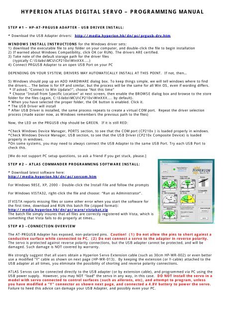
HYPERION ATLAS DIGITAL SERVO – PROGRAMMING MANUAL<br />
STEP #1 – HP-AT-PRGUSB ADAPTER - USB DRIVER INSTALL:<br />
* Download the USB Adapter drivers: http://media.<strong>hyperion</strong>.hk/dn/pc/prgusb-drv.htm<br />
WINDOWS INSTALL INSTRUCTIONS for the Windows driver sets:<br />
1) download the executable file to any folder on your computer, and double-click the file to begin installation<br />
2) If warned about Windows Compatibility, click OK (or RUN). The drivers ARE certified.<br />
3) Take note of the default storage path for the driver files<br />
(typically C:\Silabs\MCU\CP210x\WinXXX....)<br />
4) Connect PRGUSB Adapter to an open USB Port on your PC<br />
DEPENDING ON YOUR SYSTEM, DRIVERS MAY AUTOMATICALLY INSTALL AT THIS POINT. If not, then…<br />
5) Windows should pop up an ADD HARDWARE dialog box. To keep things simple, we will tell windows where to find<br />
the drivers... The below is for XP and similar, but the process will be the same for all Win OS, even if wording differs.<br />
* If asked, "Connect to Win Update?", choose "Not this time"<br />
* Choose "Install from Specific Location" at next screen, then enable the BROWSE dialog box and browse to the store<br />
folder for the files (again, C:\Silabs\MCU\CP210x\WinXXX.... by default).<br />
* When you have selected the proper folder, the OK button is enabled. Click it.<br />
* The USB Driver will install<br />
* After USB Driver is installed, the same process repeats to create a virtual COM port. Repeat the driver selection<br />
process (made easier now, as Windows remembers the previous path to the files)<br />
Now, the LED on the PRGUSB chip should be GREEN. If it is still RED:<br />
*Check Windows Device Manager, PORTS section, to see that the COM port (CP210x ) is loaded properly in windows.<br />
*Check Windows Device Manager, USB section, to see that the USB Driver (CP210x Composite Device) is loaded<br />
properly in windows.<br />
*On some systems, you may need to always connect the USB Adapter to the same USB Port. Try each USB Port to<br />
check this.<br />
[We do not support PC setup questions, so ask a friend if you get stuck, please.]<br />
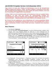
STEP #2 – ATLAS COMMANDER PROGRAMMING SOFTWARE INSTALL:<br />
* Download latest software here:<br />
http://media.<strong>hyperion</strong>.hk/dn/pc/sercom.htm<br />
For Windows 98SE, XP, 2000 - Double-click the Install File and follow the prompts<br />
For Windows VISTA32, right-click the file and choose: “Run as Administrator”.<br />
If VISTA reports missing files or some other error when you start the software for<br />
the first time, download and RUN this batch file (zipped format):<br />
http://media.<strong>hyperion</strong>.hk/dn/pc/ware/vistabat.zip<br />
The batch file simply insures that all files are correctly registered with Vista, which is<br />
something that Vista fails to do properly at times…<br />
STEP #3 –CONNECTION OVERVIEW<br />
The AT-PRGUSB Adapter has exposed, non-polarized pins. Caution! (1) Do not allow the pins to short against a<br />
conductive surface while connected to PC. (2) Do not connect a <strong>servo</strong> to the adapter in reverse polarity.<br />
The <strong>servo</strong> is protected against reverse polarity connections, but the USB adapter cannot be protected, and will be<br />
damaged. Such damage is NOT covered by warranty.<br />
We strongly suggest that all users obtain a <strong>Hyperion</strong> Servo Extension cable (such as 30cm HP-WR-002) or even better<br />
use a modified “Y” cable as shown on next page (HP-WR-013). By keeping the extension (or Y-cable) attached to the<br />
USB adapter at all times, you eliminate the possibility of shorting and reverse polarity connections.<br />
ATLAS Servos can be connected directly to the USB adapter (or by extension cable), and programmed via PC using the<br />
USB power supply. However, you may NOT “load” the <strong>servo</strong> in any way, in this case. DO NOT install the <strong>servo</strong> in a<br />
model with <strong>servo</strong> connected to control surfaces (such as ailerons, etc), and attempt to program, unless<br />
you have modified a “Y” connector as shown next page, and connected a 4.8V battery to power the <strong>servo</strong>.<br />
Failure to heed this advice can damage your USB Adapter, and possibly even your PC.
See the diagram for <strong>Hyperion</strong> ATLAS Servo connectors, left, and the<br />
pin labels on USB Adapter diagram below:<br />
The <strong>servo</strong> MUST be connected to USB Adapter correctly.<br />
GRD > BLACK wire<br />
Vcc > RED wire<br />
Tx/Rx > WHITE wire<br />
As mentioned, you may connect an Atlas Servo directly to USB<br />
adapter and program the <strong>servo</strong>, but only with <strong>servo</strong> disconnected<br />
from the model. Instead, it is much better practice to use a<br />
<strong>Hyperion</strong> “Y” cable (HP-WR-013) and modify it by disconnecting the<br />
RED wire from the connctor at USB Adapter side. In this case, you<br />
insure that the USB Adapter is never overloaded, and you can freely<br />
program and test <strong>servo</strong>s while installed and working in the model.<br />
A 4.8V battery (to 6.0V Max) is used to supply power to the <strong>servo</strong>, relieving the USB system from all loads. You may<br />
choose to also install a switch harness (HP-WR-015) between the Battery and Y-harness to allow easy power ON and<br />
OFF of the system.<br />
IMAGE BELOW SHOWS “BEST PRACTICE” WIRING CHOICE<br />
STEP #3 –PROGRAMMING<br />
The Servo Commander software will appear as left,<br />
initially.<br />
Always follow this order of connection:<br />
1) Connect USB Adapter to PC.<br />
Check that Green LED in ON<br />
2) Start Servo Commander Software<br />
3) Connect ATLAS Servo to USB Adapter<br />
4) Click the “Connect” button<br />
The software will automatically poll all COM ports on<br />
the computer, looking for the ATLAS Servo. This can<br />
take as long as 10 seconds, so please be patient.<br />
When the <strong>servo</strong> is found, the software will appear as in<br />
next image below, showing<br />
a Green “LED” and the<br />
ATLAS firmware revision of the <strong>servo</strong>.<br />
If the software fails to find a <strong>servo</strong>, a dialog box will<br />
pop up with troubleshooting tips.
Adjustments for DEFLECTION, SERVO CENTER, SPEED,<br />
and DEADBAND are made by clicking on the “slider” at<br />
the center and moving right or left to your desired<br />
value, which is shown at top right of the control display<br />
for each setting. For small adjustments, you may<br />
single click the arrows to each side of the slider<br />
buttons.<br />
To REVERSE the <strong>servo</strong>, click on the checkbox.<br />
To set compatibility with your Transmitter brand, click<br />
the arrow and choose brand from the drop-down box.<br />
“Standard” returns you to <strong>Hyperion</strong> Default for pulse<br />
widths and centering. The <strong>servo</strong> does not store this<br />
setting. It only affects the values available for<br />
<strong>programming</strong>, and sets the CENTER function to match<br />
each brand of transmitter. As a result, on reconnection<br />
of a <strong>servo</strong>, this box will display “Unknown”, but<br />
CENTER will remain set according to your previous<br />
selection.<br />
After satisfied with your selections, click the PROGRAM<br />
button to store settings in the Servo.<br />
TEST SERVO DEFLECTION does not store any settings<br />
in the Servo. It simply allows you choose an angle of<br />
deflection and, after pressing the PROGRAM button,<br />
see how far the <strong>servo</strong> will move at that setting.<br />
To RESET the Servo to ATLAS Defaults, Click the RESET TO DEFAULT checkbox, and click the PROGRAM button.<br />
Reverse: Changes the direction of rotation of the <strong>servo</strong><br />
for a given stick movement direction. Reverse is<br />
particularly useful when setting up two <strong>servo</strong>s on a y-<br />
harness to a single receiver channel, such as with<br />
separate elevator halves, for example.<br />
Servo Speed (%): You may slow the <strong>servo</strong> to achieve<br />
the selected position at a rate as slow as 1% of its<br />
normal speed of rotation, which is VERY slow indeed.<br />
This feature allows the <strong>servo</strong> to be used in applications<br />
that would normally require either an additional ‘<strong>servo</strong><br />
slow’ or pneumatics to actuate features such as hatches,<br />
doors and landing gear.<br />
Rotation (degrees): By default most <strong>servo</strong>s, including<br />
ATLAS, have 45 degrees rotation per side (90 degrees<br />
total). You may program ATLAS for as little as 15 degrees<br />
or as much as 70 degrees rotation per side. (30~140 deg<br />
total) Note that ATLAS may safely be driven - using<br />
Transmitter travel and mixing adjustments - to a max of<br />
175 degrees total rotation.<br />
Servo Center (%): The <strong>servo</strong> centre feature allows<br />
wide adjustment (approx +/- 25%) of the <strong>servo</strong> arm<br />
‘center’ position in response to the neutral signal from a<br />
transmitter. This is useful to adjust trim offsets in <strong>servo</strong><br />
installation, so that your transmitter trims can be set to<br />
neutral and therefore retain maximum in-flight trim<br />
adjustment capability.<br />
Tx Compatibility: This feature in the ATLAS Servo <strong>programming</strong> Software allows you to choose common Transmitter<br />
brands, such as JR, FUTABA, HITEC, MULTIPLEX, and “Standard”. When you choose “Futaba”, for example, the<br />
Programmer automatically sets Servo Center to match the default Futaba pulse width for Center. So the <strong>servo</strong> will<br />
properly center when you turn on your Futaba transmitter.<br />
Servo Deadband (μS): Dead Band is the range of signal over which the <strong>servo</strong> does not change position in response to<br />
a change in signal. The default value is 2μS and can be adjusted to 16μS max. This is useful for applications where two<br />
<strong>servo</strong>s are both operating one control surface, and avoids one <strong>servo</strong> ‘fighting’ the other. Also, some receivers may<br />
have a small ‘jitter’ on the output signal causing an undesirable <strong>servo</strong> ‘buzz’. If <strong>servo</strong> buzz is found then this value<br />
should be increased to the minimum level at which the buzz is eliminated.<br />
(DIGITAL <strong>servo</strong>s often have a small, constant hum. Do not confuse this natural sound with bad “buzz” that we want to<br />
eliminate!)<br />
Enjoy!<br />
The <strong>Hyperion</strong> Team<br />
All Rights Reserved, <strong>Hyperion</strong> <strong>HK</strong> Ltd., June 1 st 2007


![P01(Oxalys EP) [更新済み].ai - Kyosho](https://img.yumpu.com/26948574/1/184x260/p01oxalys-ep-ai-kyosho.jpg?quality=85)