0. [1400. 970. L,J s, [1200. 1170, LJ .Fig, 9 -I'red.iction s, [1500, 600. l..l 0. [1500,900, I.,I rig. to -Prediction 0.211 N.[l." 14001.N,IL •. 12001 8·10' 01 wear by DIN 3996 Cor ratiol 3131 <strong>in</strong> flJDCtiOD'Of ol!lllbe., of ,cycles. 0.03 ,..---------------, 0.02 0.01 1'10' 2'10' 3'10' N,ll. •• 1500] of wear by DIN 3996 for ratlo 5124- In flJDclion of number of cycles. fi~.U - Wonn geali' 1/40: n, '" 1600 FPm; C, = U74 Nrn after 2323 hours, Fig. 12- Wurm gear ~/40: II', ... 600 rpm; C, :: 1374 Nm aft!!r 4477 hOIlI'S. 34, GEAR TECHNOLOGY , ! teeth is produced becau e material is removed, but I l!he physical basi here i contact pressure. TIle <strong>in</strong>tensity 0:1' this phenomenon is direclly l<strong>in</strong>ked to <strong>the</strong> radius curvature di tribution of <strong>the</strong> worm gear. If this distribution is regular, as <strong>in</strong> one-start worm gears, <strong>the</strong> equivalent wear phenomenon will propagate slowly, and <strong>the</strong> result<strong>in</strong>g level of wear will be low. When <strong>the</strong> pre ure di tribution is not regular, as <strong>in</strong> <strong>the</strong> case of 3- or 5-start wonn gears. <strong>the</strong> ,equivalent wear phenomenon grows quickly. and <strong>the</strong> result<strong>in</strong>g wear [eve] is high. This is ob erved <strong>in</strong> Figs. 5-7. In <strong>the</strong>se cases, <strong>the</strong> heterogeneity of <strong>the</strong> worm wheel material, can produce a 11011,- homogeneity of tooth-to-tooth wear, !.hereby <strong>in</strong>duc<strong>in</strong>g pitch errors durmg work<strong>in</strong>g. These pitch error can create <strong>in</strong>temal dynamic effects caused by <strong>the</strong> bad load har<strong>in</strong>g between teeth, <strong>in</strong>creas<strong>in</strong>g <strong>the</strong> propagation of <strong>the</strong> equivalent wear phenomenon and, sometimes, <strong>the</strong> production of chocks dur<strong>in</strong>g mesh<strong>in</strong>g. A New Approach hi order to have abetter prediction of worm gear life, it is nece ary 'to have an approach based on <strong>the</strong> observed behavior of worm wheel flanks dur<strong>in</strong>g work<strong>in</strong>g. Our observations, described above, have shown that pressure contact phenomena are <strong>the</strong> basis of this k<strong>in</strong>d of prediction. This implies <strong>the</strong> need to have a good knowledge of how <strong>the</strong> worm wheel i. affected by contact pre sure fatigue. To answer to this first question, CETIM has developed experimental <strong>in</strong>vestigations to determ<strong>in</strong>e S-N curves for several bronzes on roller-di k mach<strong>in</strong>es (Ref. 6). In ano<strong>the</strong>r way CETIM ha developed an analytical method to determ<strong>in</strong>e contact pressure distribution, tak<strong>in</strong>g <strong>in</strong>to account geometry (radius of curvature),k<strong>in</strong>emalics (slid<strong>in</strong>g velocity) and elasti.city (gear tooth tiffness). By coupl<strong>in</strong>g S-N curves with contactpre sure distribution calculations, i.t is possible to predict <strong>the</strong> zones of looth flanks on which scales will appear. Then <strong>the</strong> calculation of removed surfaces can be made, and a new contact pressure distribution can be established. Tak<strong>in</strong>g <strong>in</strong>to account <strong>the</strong> cumulative damages with S-N curves, <strong>the</strong> Life of each po<strong>in</strong>t of flank surface can bepredicted as <strong>the</strong> quantity of removed material and <strong>the</strong> equivalent wear phenomena. This calculation has to be done iteratively: The contact pressure distribution is adjusted at each step, tak<strong>in</strong>g <strong>in</strong>to account <strong>the</strong> leav<strong>in</strong>g surface on worm wheel flanks. The urface strongly tressed i <strong>the</strong>n removed. lak<strong>in</strong>g <strong>in</strong>to account <strong>the</strong> contact
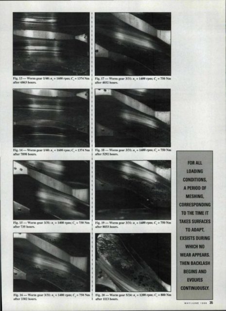
Fig. 13 - Wonn, gear 1/4.0:II', = 1600 rpm; e,,= 13'74Nm Ifig. 17 - Worm gearJlU: PI, '" 1.mo rpm; e, '" 7SO'Nm oner 686J hours, aller 40'32hours, fig. 14- Worm:gear 1140:", '" m600 rpm; C,= 1374 Nm ! !FIg. 1:8- Worm gear 3131: ", = 1400 rpm; e, = 750 Nm uftcr 7898 hours, I aner 5292 hnurs, lFig. IS - WOrn! gl!or JlJI: II, = 1400 rpm; C, = 750 Nm Fig. 19 - Worm gear 3131:n, '" 1400 rpm: e,'"750 Nm aner 735 heurs, afI.er 8OtJ3 hours. lFig.16 - Worm gear 3131: II, := 1400 rpm: ,e, :: 750 Nm ! fig. 20 - Worm ge r S/24: II, ., 11200rpm,; C, = 800 Nm LRu 330Z hours, II after U13 hears, FOR ALL LOADING CONDI11ONS. A PERIOD OF MESHING, CORRESPONDING TOTHEnMEIT TAKES SURFACES TO ADAPT. EXSISTS DURING WHICH NO WEAl APPEARS. THEN BACKlASH BEGINS AND EVOLVES CONnNUOUSLY. IIIAYIJUNIE 1991 35