Engineering - Royal Australian Navy
Engineering - Royal Australian Navy
Engineering - Royal Australian Navy

Create successful ePaper yourself
Turn your PDF publications into a flip-book with our unique Google optimized e-Paper software.
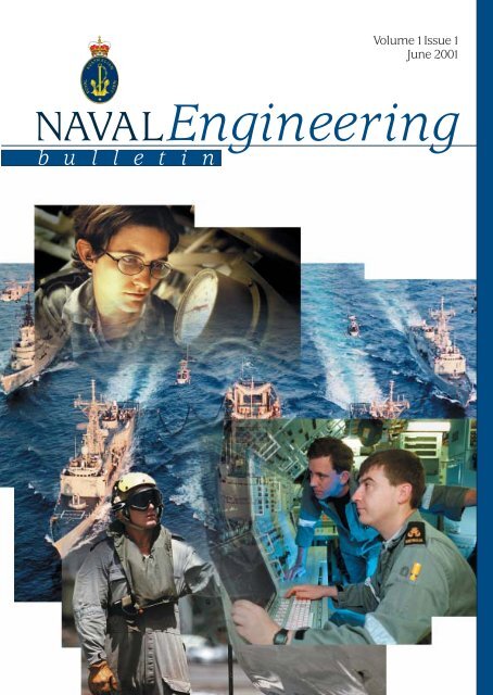
Volume 1 Issue 1<br />
June 2001<br />
NAVAL<br />
b u l l e t i n<br />
<strong>Engineering</strong>
NAVAL<strong>Engineering</strong><br />
b u l l e t i n<br />
Naval <strong>Engineering</strong> Bulletin • June 2001<br />
Contents<br />
Foreword................................................................................................................................................................................................................................................................2<br />
CNE Introduction..........................................................................................................................................................................................................................................3<br />
Word from the Editor’s Desk.........................................................................................................................................................................................................5<br />
Word from the Desk Adjacent to the Editor’s...........................................................................................................................................................5<br />
What Does MHQ’s <strong>Engineering</strong> Division Do?............................................................................................................................................................6<br />
The Impending Extinction of the Naval Engineer?............................................................................................................................................9<br />
Electric Propulsion for Surface Combatants............................................................................................................................................................13<br />
Managing <strong>Engineering</strong> & Supply Categories.........................................................................................................................................................20<br />
FIMA Sydney Circuit Card Assembly—Test and Repair Facility....................................................................................................22<br />
ADF Aerospace <strong>Engineering</strong> Professional Development........................................................................................................................ 24<br />
Professional Engineers in the <strong>Royal</strong> <strong>Australian</strong> <strong>Navy</strong>..................................................................................................................................25<br />
DNOP News......................................................................................................................................................................................................................................................27<br />
Officers’ Promotions.............................................................................................................................................................................................................................30<br />
Sailors’ Promotions..................................................................................................................................................................................................................................31<br />
LPA’s, The Opportunity Beckons............................................................................................................................................................................................36<br />
A Mine for Posterity...............................................................................................................................................................................................................................38<br />
HMAS WALLER’s Brush with the Cookie Cutter Shark.............................................................................................................................39<br />
A Word from the <strong>Engineering</strong> Sailor’s Poster.......................................................................................................................................................40<br />
NAVSYS Professional Officer Development..............................................................................................................................................................41<br />
2000 Graduates......................................................................................................................................................................................................................................... 42<br />
Defence force Qualifications Recognised................................................................................................................................................................. 42<br />
Hot Corrosion of Marine Gas Turbine Blades........................................................................................................................................................43<br />
Solar Sailor....................................................................................................................................................................................................................................................... 50<br />
Maintaining Proficiency Levels in <strong>Engineering</strong>....................................................................................................................................................51<br />
Warfare division NBCD Cell in Maritime Headquarters............................................................................................................................52<br />
Air Conditioning & Ventilation systems on Surface Ships ...................................................................................................................54<br />
History of Maintenance in the RAN.................................................................................................................................................................................. 60<br />
The Implications of Revised MARPOL Regulations on RAN Tankers.....................................................................................62<br />
The ANZAC Solution to the Technical Regulation System..................................................................................................................65<br />
Demographics, People and Technology—A Supervisor’s Perspective................................................................................... 68<br />
Dedicated to the Engine room Depts., HMA Corvettes.............................................................................................................................. 70<br />
Ha Ha Pages.....................................................................................................................................................................................................................................................71<br />
The Rivet.............................................................................................................................................................................................................................................................72<br />
1
Naval <strong>Engineering</strong> Bulletin • June 2001<br />
Foreword<br />
By Vice Admiral David Shackleton AO RAN<br />
Chief of <strong>Navy</strong><br />
Welcome to the first edition of the new Naval <strong>Engineering</strong><br />
Bulletin. This Bulletin is all about communicating with our<br />
people. Although it has a focus on engineering, it is not<br />
meant to be just for the “techos”. I commend it to the wider<br />
defence community as means of sharing ideas, evoking<br />
thought and providing feedback on this very important<br />
aspect of the RAN.<br />
As the Chief of a modern <strong>Navy</strong>, I see our harnessing of technology<br />
as fundamental to our ongoing success and effectiveness.<br />
<strong>Engineering</strong> is the business of putting technology<br />
into practice. <strong>Engineering</strong> is, and will continue to be, fundamental<br />
to the ongoing operation and effectiveness of our<br />
<strong>Navy</strong>.<br />
We have come a long way with <strong>Engineering</strong> in the RAN.<br />
Our drive to be at the technological forefront has gained us<br />
a war fighting edge and allows us to enjoy world- wide reputation<br />
for excellence. In the past, the RAN has relied heavily<br />
on using other <strong>Navy</strong>’s platforms and with that came a<br />
host of engineering, logistic and training support systems.<br />
In today’s RAN, however, we have now gone our own way in<br />
many respects through in-house Ship and Submarine building<br />
programs and on going weapon system integration programs<br />
in all our platforms, including the new Sea Sprite<br />
helicopters. We have come of age, but with that comes the<br />
impost of being a “parent <strong>Navy</strong>”. This carries with it enormous<br />
responsibilities and challenges and engineering prowess<br />
will be the key to our future. I look forward to reading<br />
about these issues in this, and future editions of the Naval<br />
<strong>Engineering</strong> Bulletin.<br />
discuss the engineering aspects<br />
of safety and risk, and<br />
as an adjunct to the RAN<br />
safety brochure “Seaworthy”.<br />
There are many facets to engineering<br />
that might be addressed in this Bulletin. To many,<br />
“engineering” evokes images of coal and steam and lands<br />
of “whirling death” and to others it is all about analysing<br />
complex electronic circuit faults or debugging software<br />
problems. In any case there is many a good “warrie” to be<br />
spun, and hopefully a few lessons to be learnt along the<br />
way. Importantly, there are also many “people issues” to be<br />
discussed and the Naval <strong>Engineering</strong> Bulletin should provide<br />
an excellent forum to do so. I hope the Naval <strong>Engineering</strong><br />
Bulletin will continue to cater for a mix of interests<br />
as it has attempted to do this time, and I encourage you to<br />
contribute articles for future editions.<br />
I trust you will enjoy this first edition of the Naval <strong>Engineering</strong><br />
Bulletin. Engineers make it happen!<br />
David Shackleton<br />
Vice Admiral AO RAN<br />
Chief of <strong>Navy</strong><br />
Leading edge technology and striving to be the best does<br />
not, however, come without risk. As the <strong>Navy</strong>’s Safety Manager<br />
I carry the ultimate responsibility for safety and for<br />
the minimisation of risk. Whilst we have relatively mature<br />
risk management systems in place, the surest way to manage<br />
risk is to eliminate it all together. In the majority of<br />
cases, the ultimate way to eliminate risk is to engineer it<br />
out of a system, or to ensure it is not embedded in the design<br />
in the first case. Under the technical regulatory framework,<br />
I rely on engineers to advise and to assure me as to<br />
safety and fitness for purpose of our Ships, Submarines and<br />
Aircraft. I see the Naval <strong>Engineering</strong> Bulletin as a forum to<br />
2
Naval <strong>Engineering</strong> Bulletin • June 2001<br />
CNE Introduction<br />
I remember when I was a Lieutenant at sea in the late 1970’s<br />
eagerly awaiting the next issue of the Fleet Maintenance<br />
Bulletin. It was full of interesting articles by engineers and<br />
technicians; some serious discussing issues facing engineering,<br />
some informative about new technologies that were to<br />
be introduced into <strong>Navy</strong> (like gas turbines!), and some for a<br />
bit of a laugh like someone proposing we could launch gliders<br />
by attaching them to 4.5" shells. The articles were<br />
graphically illustrated with cartoons and as a young engineer<br />
I was fascinated by the Bulletin as it gave me a window<br />
on the world of engineering in <strong>Navy</strong>. It was a forum for<br />
communication, information and discussion of issues. It was<br />
part of the Profession of Naval <strong>Engineering</strong>. The Fleet Maintenance<br />
Bulletin evolved into the Naval <strong>Engineering</strong> Bulletin<br />
in the late ‘80’s and then just disappeared a few years<br />
ago.<br />
With this issue we see the return of the Naval <strong>Engineering</strong><br />
Bulletin. It will again be the forum for communication, information<br />
and discussion of engineering issues in <strong>Navy</strong>. It<br />
will be your window to our new world of engineering in<br />
<strong>Navy</strong>.<br />
As CNE, I am the professional head of <strong>Engineering</strong> in the<br />
RAN and Head of Corps for the <strong>Engineering</strong> Branch. I am<br />
responsible for providing CN with specialist advice on engineering,<br />
defining <strong>Navy</strong>’s engineering requirements and advising<br />
on engineering personnel matters. I am concerned<br />
that the contribution that engineering expertise and experience<br />
is making within the <strong>Navy</strong> has been declining for a<br />
number of years, and as a result the status of engineering<br />
in <strong>Navy</strong> needs significant improvement. My aim is to promote<br />
the contribution that sound engineering advice, professional<br />
judgement and the skills of engineers and<br />
technicians, both uniformed and civilian can make to <strong>Navy</strong>.<br />
During the last ten years the RAN has undergone significant<br />
organisation and procedural changes that have impacted<br />
on the delivery of engineering. Our current structure,<br />
training, administration and employment of engineering<br />
personnel may not now align well with the needs of a modern<br />
<strong>Navy</strong> operating smaller, minimum manned ships that<br />
commercially supported. The proposed new acquisitions<br />
outlined in the recent White Paper will also effect <strong>Navy</strong>’s<br />
requirement for engineering<br />
expertise.<br />
While engineering in <strong>Navy</strong><br />
today is different to when I<br />
was a Lieutenant at sea in a<br />
DDG, it is just part of an evolution of engineering that has<br />
seen the change from sail to steam, from paddlewheels to<br />
screw propellers, from burning coal to burning liquid fuel,<br />
from large calibre guns to missiles, and the list goes on.<br />
These changes in technology have been accompanied by<br />
changes to manning, employment, skill requirements, training,<br />
logistic support and management. So be reassured,<br />
there is still a fundamental need for engineering in <strong>Navy</strong>, it<br />
is just different now, and we need to adapt to the changes.<br />
My objectives as CNE include:<br />
• Consulting widely and improving communication<br />
amongst engineering personnel by initiatives such<br />
as this Naval <strong>Engineering</strong> Bulletin, and engineering<br />
seminars;<br />
• Reviewing <strong>Navy</strong>’s requirement of its engineering personnel<br />
and how they may best contribute to <strong>Navy</strong><br />
capability. This would include how engineering personnel<br />
should be organised and structured, and<br />
what education, training and experience they require.<br />
A high priority will be examining the employment<br />
of technical personnel ashore and the<br />
employment of junior engineering officers;<br />
• Examining what engineering and technical personnel<br />
require of <strong>Navy</strong> in such areas as job satisfaction,<br />
career progression, and personal development;<br />
• Refining the engineering processes within <strong>Navy</strong>; and<br />
• Being a key player in the new officer promotion system<br />
and in decisions impacting technical personnel.<br />
• Raising the profile of engineering in <strong>Navy</strong>.<br />
In summary, my objective is to reinvigorate Naval <strong>Engineering</strong>!<br />
So enjoy this first issue of the Naval <strong>Engineering</strong> Bulletin. To<br />
ensure it continues I encourage you all to contribute to it.<br />
3
Naval <strong>Engineering</strong> Bulletin • June 2001<br />
Finally, I would like to thank those people without whose<br />
efforts this Bulletin would still be just another good idea -<br />
CAPT Craig Kerr, LCDR Tom Munneke and MIDN Angela<br />
Andrews.<br />
Editorial Board<br />
Ken Joseph<br />
Commodore, RAN<br />
CNE<br />
About the Author<br />
Commodore Kenneth W. Joseph was born 16 April 1954 in Sydney.<br />
He joined the <strong>Royal</strong> <strong>Australian</strong> Naval College in 1971. He<br />
then attended the University of New South Wales in 1973,<br />
graduating in 1976 with a Bachelor of Electrical <strong>Engineering</strong><br />
Degree. This was followed by engineering courses with the<br />
<strong>Royal</strong> <strong>Navy</strong> and with the United States <strong>Navy</strong> in 1977/78.<br />
He served in the destroyer, HMAS PERTH from 1978 - 80, where<br />
he managed the ASW and Gunnery systems. As a young Lieutenant<br />
in 1981/82 he served on the staff of the Director Naval<br />
Weapons Design, primarily concerned with the design and<br />
manufacture of the <strong>Australian</strong> indigenous sonar known as<br />
“MULLOKA”. From 1982 - 85 he served as the Resident Naval<br />
Engineer at the sonar manufacturer’s plant.<br />
In 1985 he returned to sea as the Weapons Electrical <strong>Engineering</strong><br />
Officer of HMAS PERTH which won awards for Gunnery<br />
and Missile system excellence, and the effectiveness of<br />
ASW, AIO and Communications systems. In 1987 he was<br />
posted ashore as the Officer in Charge of the Trials Unit at the<br />
<strong>Royal</strong> <strong>Australian</strong> <strong>Navy</strong> Trials and Assessing Unit. His responsibilities<br />
included the trials and acceptance recommendations<br />
of all new, modified or overhauled ships, aircraft and other<br />
operational systems.<br />
In 1991, he was posted to the Naval Postgraduate School in<br />
Monterey, California to pursue a Master of Science degree in<br />
Management. His thesis addressed Operational Test and<br />
Evaluation (OT&E), and he graduated With Distinction in<br />
1992. On returning to Australia in February 1993 he served<br />
with the Director Naval <strong>Engineering</strong> Requirements - Warfare<br />
Systems where he progressed policies on OT&E and Operational<br />
Software <strong>Engineering</strong> Management.<br />
In November 1993, he was posted as the <strong>Engineering</strong> and Support<br />
Director for the Offshore Patrol Combatant Project, where<br />
he was responsible for the management of the ship design<br />
and proposed Integrated Logistic Support during the Project<br />
Design Phase. In February 1995, he was promoted to Captain<br />
and appointed as the Director Capability Development and<br />
Analysis in Force Development (Sea). The appointment as<br />
the Minehunter Coastal Project Director followed in December<br />
1996 where he achieved the successful delivery of the first<br />
two ships. He was promoted to Commodore in December 1999<br />
and posted as the inaugural Director General Naval Systems<br />
in March 2000. He was appointed as the Chief Naval Engineer<br />
in September 2000.<br />
Chairman<br />
Captain Craig G. Kerr, RAN<br />
Members<br />
<strong>Engineering</strong> Advisory Council (EAC)<br />
Editor<br />
Lieutenant Commander Tom Munneke, RAN<br />
Published by<br />
Defence Publishing Service<br />
Disclaimer<br />
The views expressed in this Bulletin are the personal views<br />
of the authors, and unless otherwise stated, do not in any<br />
way reflect <strong>Royal</strong> <strong>Australian</strong> <strong>Navy</strong> Policy<br />
Deadline<br />
December 2001 Edition<br />
5 October 2001<br />
Contributions should be sent to<br />
The Editor,<br />
Naval <strong>Engineering</strong> Bulletin<br />
CP4-7-138<br />
Campbell Park ACT 2600<br />
Telephone: (02) 6266 4212<br />
Fax: (02) 6266 2388<br />
or email: navalengineeringbulletin@cbr.defence.gov.au<br />
Distribution<br />
To be added to the distribution list contact the Editor.<br />
4
Naval <strong>Engineering</strong> Bulletin • June 2001<br />
Word from the Editor’s Desk<br />
My sincere thank-you must go out to those people who have the farsightedness<br />
that the RAN engineering community required a conduit to articulate<br />
the views of its personnel and contributed to its reappearance; namely the<br />
Naval <strong>Engineering</strong> Bulletin. The June 2001 submissions are varied in both size<br />
and content and should spark an interest in most of us. The articles deal<br />
with ‘The Job We Do’ to researched papers which have previously been submitted<br />
for inclusion in <strong>Engineering</strong> Society journals. Unfortunately not all<br />
contributions made this bulletin, but we will be holding space in future additions.<br />
It is a matter of achieving balance and thus overall interest. It is<br />
envisaged that the bulletin should reflect all engineering streams, aeronautical,<br />
marine, ordnance and weapon, for both the professional engineer and<br />
techos alike. Thus future submission should come from the broad streams<br />
of engineering personnel. A submission on your job, your organisation, your<br />
ideas, your expectation, your curiosity or just a ditty will be appreciated. Do<br />
not forget the graphic input. It’s acknowledged that both individually and collectively we are extremely busy and involved<br />
in our own particular part in the ADF but it’s critical that some time is spent on expressing those issues, matters that relate<br />
to us or just to press your case to like minded people.<br />
Should there be any topics you feel need to be covered in future issues, be they <strong>Engineering</strong> specific, or general bulletin<br />
layout please write to us. Letters to the Editor will also be appreciated to keep us on our toes. I have enjoyed the involvement<br />
and editing the revived Bulletin and hope that the challenge will be met to continue its publication. We engineers and<br />
techos deserve it.<br />
Lieutenant Commander Tom Munneke<br />
Word from the Desk adjacent to the<br />
Editor’s<br />
A few short months ago this Naval <strong>Engineering</strong> Bulletin was still just a ‘good<br />
idea’. Finally we are down to the business end of things - and I hope everyone<br />
out there enjoys reading this magazine as much as we enjoyed putting it<br />
together.<br />
All I have to say is a great amount of thanks to all those people who submitted<br />
articles, and especially to those who conveyed their encouragement and<br />
praise for this project. Sadly we couldn’t print all the articles that were submitted,<br />
including my own commentary on how to make the <strong>Navy</strong> more effective<br />
(by reversing the chain of command - put the Midshipmen in charge!)<br />
however everything that wasn’t included this time has been collated for use<br />
in the next edition. Keep those contributions flowing! Thanks also have to<br />
go to Rob Corrigan for his graphical contribution.<br />
The future of this magazine is in your hands, so let’s maintain the enthusiasm and keep it happening.<br />
Midshipman Angela Andrews<br />
5
Naval <strong>Engineering</strong> Bulletin • June 2001<br />
What Does MHQ’S <strong>Engineering</strong> Division<br />
Do?<br />
By CMDR Damien Allan, RAN<br />
This article is intended to re-acquaint the wider engineering<br />
community with the purpose and activities of the Chief<br />
Staff Officer (<strong>Engineering</strong>) (CSO(E)) organisation given the<br />
vast changes of the last few years, as well as introduce the<br />
incumbent Fleet Engineers. The many changes throughout<br />
the <strong>Navy</strong> have not appreciably changed the structure<br />
and function of the <strong>Engineering</strong> Division at Maritime Headquarters<br />
(MHQ), but the relationships and dynamics of the<br />
new players do seem to constantly evolve and change. In<br />
particular, the creation of the Force Element Group (FEG)<br />
concept has led to some hard thinking about the division<br />
of labour between MHQ and the FEGs.<br />
The focus of MHQ is ostensibly at three levels. The first is to<br />
oversee the daily exchange of information between ships<br />
and MHQ to ensure those problems and issues, such as Urgent<br />
Defects (URDEF), are addressed appropriately. The<br />
<strong>Engineering</strong> Division’s (ENGDIV) concentration of wide technical<br />
and personnel experience results in a synergy that<br />
can be used to lock onto and solve problems quickly, allowing<br />
ENGDIV to “punch beyond its weight”. Often the<br />
Fleet Engineers act as a sanity check to ensure that the root<br />
causes of problems are identified when the incoming information<br />
doesn’t quite sound right. This watching brief<br />
extends to all classes of ship, regardless of who is the Administrative<br />
Authority.<br />
The second level of focus relates to ENGDIV’s audit function<br />
of MFUs. This is to advise the Maritime Commander<br />
(MC) whether his ships are safe and capable of accomplishing<br />
their required missions, and involves assessing both the<br />
ships’ material state and overall departmental efficiency.<br />
To this end, the Fleet Hull <strong>Engineering</strong> Officer (FHEO), Fleet<br />
Marine <strong>Engineering</strong> Officer (FMEO) and Fleet Weapons<br />
Electrical <strong>Engineering</strong> Officer (FWEEO) are available to advise<br />
and discuss any problems faced by ships’ technical<br />
departments, and have the authority to set policy on operational<br />
engineering practice in the Fleet.<br />
The third level of focus is in the long-term development of<br />
the Fleet’s engineering capability. This may be to provide<br />
technical backing for specific issues being addressed by the<br />
MC, but more frequently involves progressing people’s qualifications<br />
via the various Charge Programs and Boards. As<br />
an ENGDIV Head of Department, the Commander Fleet<br />
Maintenance (CFM) is tasked with developing the professional<br />
skills of all people within FIMAs so that they are better<br />
able to serve in their next ship.<br />
A new and vital aspect of this long-term focus is MHQ’s relationship<br />
with the FEGs and Naval Systems Command<br />
(SYSCOM). As the capability managers and developers, the<br />
FEGs and associated Sustainment Maintenance Offices<br />
(SMOs - formerly CLOs) will seek MHQ advice on a broad<br />
range of engineering issues affecting our ability to fight, win<br />
and survive at sea. Similarly, engineering policy being processed<br />
by SYSCOM will often have important MHQ input.<br />
The variety of topics recently dealt with by MHQ spans from<br />
creating sustainable personnel structures, to creating the<br />
new RAN paint system, to a first hand inspection of STS<br />
YOUNG ENDEAVOUR’s rigging to assess safety equipment.<br />
An important aspect of MHQ’s cross FEG activities is to ensure<br />
that consistent and universal standards are maintained,<br />
thereby preventing the seven FEGs becoming seven<br />
separate navies.<br />
Life on Level 4 MHQ is always interesting. If a ship could<br />
have sorted it out, it would have done so before asking us.<br />
The PLAYERS<br />
MHQ <strong>Engineering</strong> Division<br />
CAPT PAUL Field (GLEN ME) presently heads the <strong>Engineering</strong><br />
Division, which includes the FMEO, FWEEO, FHEO, CFM<br />
(all FIMAs), Fleet Environment and OH&S Coordinating Officer,<br />
MOTU ME (Fleet Pneumatics, FFG Trainer, FCAU, Fleet<br />
Boiler Inspector, Fleet Diesel Inspectors), MOTU WE (DLG<br />
Stuff) and CQ Charge Boards, as CSO (E). Besides providing<br />
engineering advice to FEGs and COMFLOT, he is a promotion<br />
board member for LEUT to LCDR and is responsible<br />
for advising MC on submarine and aviation engineering<br />
matters. Calibration Ranging is done by FIST who is part of<br />
the Surface Combatant FEG. His recent jobs include a sabbatical<br />
with IBM during the 2000 Olympic Games and a stint<br />
as FMEO. He was a founding member of the Class Logistics<br />
Executive, which sponsored major changes within Naval<br />
Support Command.<br />
6
Naval <strong>Engineering</strong> Bulletin • June 2001<br />
CSO (E)’s ‘upwards looking’ functions are to advise the MC<br />
on engineering issues by distilling the detail from his engineering<br />
heads of department, and to represent the Maritime<br />
Command’s interests in engineering matters. This<br />
requirement manifests itself in the three weekly briefs and<br />
presentations attended by all operational, engineering and<br />
logistic stakeholders within the Headquarters.<br />
‘Downward looking’ functions are to ensure that ENGDIV<br />
runs smoothly and that correct decisions are made at the<br />
appropriate levels. External to MHQ, the scope of the job is<br />
very wide, and includes all surface ships, submarines, aircraft<br />
and FIMA workshops. Primarily, CSO (E)’s concerns<br />
are to ensure that the MC’s assets can safely meet all of their<br />
required operational objectives. Daily signal traffic from<br />
ships describing URDEFs and Occupational Health and<br />
Safety (OH&S) incidents are the focus of this.<br />
Fleet Marine <strong>Engineering</strong><br />
FME is comprised of two main areas headed up by the Fleet<br />
Marine Engineer Officer (FMEO) CMDR Gavin Irwin. These<br />
components are the headquarters staff on level 4 MHQ, and<br />
the more diverse MOTU-ME component, which includes:<br />
• FFG PCS Trainer - provides training in the operation<br />
and maintenance of the FFG propulsion control system<br />
and centre of excellence for FFG propulsion systems<br />
• Fleet Condition Assessment Unit (FCAU) - lead navy<br />
unit for Vibration Analysis, Oil Analysis, and other<br />
machinery condition assessment tools<br />
• Fleet Pneumatic Specialists (FPS) - originally specialists<br />
in DDG combustion control pneumatics but now<br />
expanding to cater for the plethora of different pneumatic<br />
control systems in the Fleet<br />
• Fleet Diesel Inspector (FDI) team - new and growing<br />
team formed to raise the level of diesel expertise<br />
within the RAN. Trained on the USN Diesel Inspector<br />
course they will be used to assist ships with inspections,<br />
defect investigation and provide general<br />
diesel engine advice.<br />
The MHQ staff comprising FMEO, Deputy Fleet Marine <strong>Engineering</strong><br />
Officer (DFMEO), 4 x Fleet Marine <strong>Engineering</strong><br />
Assistant (FMEAs) Warrant Officers and the Fleet Boiler Inspector<br />
(FBI) are most frequently encountered by ships in<br />
their Sea Training Group role, wearing green overalls and<br />
carrying gas masks. Whilst these visible roles during Light-<br />
Off Examinations (LOEs), Work-Ups and Operational Readiness<br />
Examinations (OREs) form a large and important part<br />
of FME activity, they also have less public, but equally important<br />
jobs ashore. Such tasks include the daily oversight<br />
of URDEFs to facilitate appropriate responses, the audit of<br />
engineering practises against safety and operational standards<br />
and administration of the Marine <strong>Engineering</strong> Charge<br />
qualification programs. In addition provide engineering<br />
advice to the MC, CSO(E), FEGs and ships, as well as the critical<br />
tasks of representing Fleet <strong>Engineering</strong> concerns to<br />
SYSCOM and <strong>Navy</strong> Headquarters (NHQ), and the implementation<br />
of operational <strong>Engineering</strong> policy.<br />
This is just a brief snapshot of who we are and some of<br />
what we do. At the end of the day we exist to ensure that a<br />
ship’s <strong>Engineering</strong> department can safely and effectively<br />
operate and maintain their ships at sea so that the ship can<br />
fulfil its warfighting role.<br />
Fleet Hull <strong>Engineering</strong><br />
The present FHEO is CMDR Allan (GLEN ME). He has the<br />
honour of having his name on the shortest nameboard at<br />
MHQ due to previous incumbents averaging seven years in<br />
the job. This position was originally called the Fleet Shipwright,<br />
and was the domain of senior shipwright branch<br />
officers. The long tenure of the position (to retirement) gave<br />
an important thread of continuity within ENGDIV, but this<br />
traditional career approach has changed due to the gradual<br />
evolution in branch structure.<br />
The FHEO’s main job is to audit the condition of surface<br />
ship hulls to ensure that they remain certified for unlimited<br />
operations where ship design permits. Every Departmental<br />
Audit will see the FHEO and the Fleet Hull Engineer<br />
Assistant (FHEA) Warrant Officer examining the departmental<br />
administration as well as accessing the deepest<br />
darkest corners of bilges, fan flats, ballast and fuel tanks.<br />
For this reason, notice will be given as to which tanks are to<br />
be emptied and cleaned in advance of the inspection. These<br />
physical inspections assess paint deterioration, corrosion<br />
wastage and structural cracking.<br />
The FHEO also deals with a wide variety of other platforms<br />
systems, such as<br />
• Steering gear and stabilisers<br />
• Sewage processing plant<br />
• Marine pollution processing systems<br />
• Refrigeration<br />
• Air conditioning and ventilation<br />
• Nuclear, Biological & Chemical Defence (NBCD)<br />
equipment<br />
• Rigging and lifting equipment<br />
• Ships’ boats<br />
• Pressure vessels and hoses<br />
• Low and High Pressure air systems<br />
One big initiative being progressed is the introduction of<br />
low gloss, low solar absorbent paint into RAN service. The<br />
technical merits of this new polyurethane paint make it<br />
demonstratively better than the alkyd paints now being<br />
phased out, but these benefits will not be realised without<br />
7
Naval <strong>Engineering</strong> Bulletin • June 2001<br />
addressing issues such as training and logistic support.<br />
Therefore, FHEO must liaise with other authorities to ensure<br />
that people are trained to properly prepare surfaces<br />
and apply two pack paints. The logistics end must ensure<br />
application data supplied to contractors is correct, and that<br />
the painting technology sailors are trained to use is readily<br />
available in ships. Otherwise, experience has shown that<br />
ships’ staffs will often feel compelled to make do and risk<br />
poor results for a short-term fix. The present MC is keen on<br />
making sure that RAN ships look good, so a well-monitored<br />
and controlled implementation strategy will help everyone<br />
meet his expectations.<br />
Another new area for FHEO, given the introduction of Defence<br />
Instruction - <strong>Navy</strong> (TECH) 47-3, is classification requirements<br />
for warships. This is in keeping with the<br />
requirement for the <strong>Navy</strong>, and Maritime Command in particular,<br />
to be an informed customer in the change process.<br />
Although SYSCOM and elements of the Defence Material<br />
Organisation (DMO) are driving the warship classification<br />
issue, it is important for ENGDIV to understand how this<br />
translates into better and more battle worthy ships.<br />
FHEA1 (WOMT Dickey Collinson) and FHEA2 (POMT PHIL<br />
Kelly) who have a formidable knowledge of the RAN’s platforms<br />
and hull administration ably assist the FHEO.<br />
Due to space constrained, more will be published on the<br />
FWEEO and CFM’s organisations in the next issue.<br />
About the Author<br />
Commander Allan has recently served as Acting Commander<br />
Fleet Maintenance and as the Platform System Support Manager<br />
within the Mine Warfare CLO. As MEO of HMAS HO-<br />
BART and Naval Representative during the refits of HMAS<br />
BRISBANE, PERTH and MANOORA, he has had extensive experience<br />
in machinery, hull and contracting issues.<br />
The less glamorous side of the job is its jurisdiction over<br />
sewage processing equipment, but fortunately, this is not a<br />
regular hand on commitment. Nevertheless, as potential<br />
killers, sewage systems have FHEO’s close attention.<br />
8
Naval <strong>Engineering</strong> Bulletin • June 2001<br />
The Impending Extinction of the<br />
Naval Engineer?<br />
By LCDR Mark Warren, RAN<br />
To date the RAN has followed the lead of the RN in finding<br />
a place for engineers at sea. This has stood in contrast to<br />
the USN, which has preferred to send the maintainers and<br />
leave the engineers at home. With increasing sophistication<br />
of designs and the drive toward genuine minimum<br />
manned ships such as in DD-21, it will only be a matter of<br />
time before the RAN will have to give serious consideration<br />
to joining the USN. What bang for it’s buck will the RAN get<br />
for sending engineers to war?<br />
Reduced Benefit<br />
It is easy to fall into the misconception that the more technically<br />
sophisticated the machinery, the greater the need<br />
for technical training for the operators. Actually the reverse<br />
is usually true. In their infancy engineering designs are<br />
tenuous, temperamental, and simple. The engineer is required<br />
to make on site adjustments to the design or to work<br />
around bad design. However, as the design (and the design<br />
process) matures, the need & capacity for on board tinkering<br />
diminishes. The car is an obvious example of this trend.<br />
30 years ago, engineering nous could make a real difference<br />
to your motoring experience. Today it is almost a hindrance<br />
- just get in and drive. Likewise the user friendliness<br />
of computers is light years ahead of the early 1980s. In the<br />
Naval sphere, engineering in an early steam plant required<br />
constant attention to detail and consideration of the design.<br />
In contrast a gas turbine just runs itself. Today marine<br />
engineering input on<br />
board is limited to blade inspections,<br />
the analysis of<br />
which could really be done<br />
anywhere. Likewise the weapons<br />
world has moved long past<br />
the requirement for engineering<br />
decisions to be made at<br />
sea. At a recent Naval Engi-<br />
neering Symposium a senior WE officer acknowledged that<br />
he had not seen one significant engineering problem resolved<br />
on board. The time for that has passed.<br />
Cost Pressure<br />
In that environment, the push to reduce manning to reduce<br />
operational costs such as in the DD-21 project adds even<br />
more heat. To achieve a significant reduction in manning<br />
will require solutions outside the box. However it can’t be<br />
avoided that people are there to fight the ship, and so it can<br />
be expected that skill sets will be offloaded or amalgamated<br />
in accordance with how they contribute to that process.<br />
Trying to quantify that value is obviously a moot point in<br />
what can be parochial environment. Furthermore, the reality<br />
of having to operate a ship in peacetime cannot be<br />
ignored. Nevertheless engineering properly considered belongs<br />
more to the preparation phase of war than to the battle<br />
and so the naval engineer can expect to feel a significant<br />
component of the cost pressure.<br />
Cost Benefit Analysis<br />
On today’s practices, an engineer of a ship has been under<br />
training for 6 years (including university studies), and spent<br />
a further 6 years gaining the experience necessary to take<br />
up charge employment. As a seminal article this is not the<br />
place for a detailed cost analysis.<br />
However a ‘back of the envelope’<br />
type costing suggests<br />
that Defence invest $13M pa to<br />
train the engineers it will need<br />
in the future for charge appointments.<br />
1 On the basis that<br />
trained engineers are adding<br />
value, the cost of the six-year<br />
period of experience is the additional<br />
cost of employing<br />
1 This is calculated as follows (0.25*17*(130*4+60*2)+0.50*17*(65*4+60*2)+0.25*17*(25*4+60*2))*1.88 = $13M representing 34 charge engineers at sea for 2yr<br />
appointments (17), and the estimated cost of training via ADFA, RMIT, and Undergraduate Entry respectively iaw the proportion which each entry type<br />
was represented by charge engineers at sea in the year 2000. The factor 1.88 represents a 10% wastage rate in the 6 years after training.<br />
9
Naval <strong>Engineering</strong> Bulletin • June 2001<br />
someone in uniform over civilian public servants and contractors,<br />
which is in the order of $3M pa. Consequently the<br />
total cost of providing professional engineer candidates for<br />
the charge positions at sea is in the<br />
order of $16M pa. What does the<br />
<strong>Navy</strong> get for its $16M apart from a<br />
wardroom wine caterer and a TV<br />
tuner?<br />
In discussing the benefits it is important<br />
to be clear on what a professional<br />
engineer is. As a head of<br />
department the engineer offers<br />
technical team management and<br />
leadership and engineering advice<br />
to the command. However while<br />
an engineer may perform these<br />
functions well, these are more military & managerial skills<br />
and could be performed by non- engineers. Engineers are<br />
not mechanics or technicians - they are not trained to operate<br />
or repair systems. And although closely related engineering<br />
is not strictly the same as logistics - the gathering<br />
of technical data and support to ensure the through life<br />
support. Engineers have something to offer and something<br />
to learn from such disciplines in the matrix of industrial<br />
operations. However professional engineers offer something<br />
different - they are targeted at the design process. This is<br />
reflected in the IEAUST website, which describes <strong>Engineering</strong><br />
as involving “the application of science and technical<br />
knowledge to create systems, services, products and materials”.<br />
This is not to suggest that engineering is restricted<br />
to the R&D departments of companies such as GE or<br />
Raytheon. The application of engineering skills is just as<br />
relevant to the maintenance and improvement aspects of<br />
the life cycle. On board ship the professional engineer provides<br />
analytical skills, technical specification of maintenance,<br />
and technical appraisal of improvements to design.<br />
How can the benefit of having such a person in the modern<br />
naval battle be quantified? When I met an engineer at a<br />
manufacturing plant that made water meters, he pointed<br />
out that his employment was subject to being able to show<br />
how much his technical input improved the financial performance<br />
of the company. The value adding was a relatively<br />
simple equation. In defence, quantifying the output<br />
is not so straightforward.<br />
However defence is still measured by dollars. There is not a<br />
bottomless pit of money. It is easy to slip into the consumer<br />
attitude of, “How can we spend the money so that we make<br />
sure we get as much if not more for ourselves next year.”<br />
But as professional engineers should take the producer attitude<br />
and ask, “How can we maximise our defence capability<br />
over time for each dollar that is spent.” It is certainly<br />
harder to quantify military capability than the life cycle cost<br />
of a water meter, but it can be done.<br />
One measure of capability relevant<br />
to Naval Engineers could be operational<br />
availability vs cost. At the<br />
2000 <strong>Engineering</strong> Symposium, the<br />
then CSO(E) presented data showing<br />
that the refit & repair budget<br />
had decreased by half over the last<br />
10 years. Not a bad return for $16M<br />
pa! But then how much of that<br />
drop can be attributed to Naval<br />
Engineers at sea, and how much to<br />
the engineering improvements on<br />
the ships we buy and the changing<br />
industrial environment of defence<br />
industry? It would be hard to quantify, but probably<br />
not much could be attributed to charge engineers (remember<br />
we are not talking about the number of engineers involved,<br />
but the fact that one of those engineers is the charge<br />
engineer of the ship).<br />
Another possible measure could be taken as the weighted<br />
percentage of mission critical repairs effected by engineering<br />
input. This is more obviously connected with the engineer<br />
being at sea. The professional engineer clearly adds a<br />
different perspective and analytical tool which, when combined<br />
with the tradesman/technician’s nous, significantly<br />
improves the problem solving capacity of the department.<br />
It is still common in the mechanical world at least for mission<br />
critical problems to be resolved with the professional<br />
engineer’s contribution. However, as noted above with increasing<br />
sophistication of design this has decreased over<br />
time.<br />
While the engineer does value add to life at sea, it is difficult<br />
to see how the profession can survive the next round<br />
of personnel cost-cutting, unless figures are produced that<br />
point to a significant impact which is not apparent at first<br />
look. Not that this suggests the <strong>Navy</strong> doesn’t need engineers.<br />
As noted above, engineers bring science to life, and<br />
the modern battlefield is at least in part a battle of engineering<br />
superiority. Rather the question is should the <strong>Navy</strong><br />
send them to war? Of course not many captains would<br />
knock back one if one were on offer. But taking the bigger<br />
picture, what’s the best way to spend the limited defence<br />
budget.<br />
A Different World<br />
One world that has already had to face this question is the<br />
aeronautical world. Of course they’ve had to face it right<br />
from the start for space and weight reasons, but although<br />
10
Naval <strong>Engineering</strong> Bulletin • June 2001<br />
the reason they minimise the personnel present is different,<br />
they have shown what is possible. For instance a FA-18<br />
Hornet has as much platform and weapons sophistication<br />
as an FFG with about 0.5% of the personnel present! The<br />
pilot is trained to understand the engineering operating<br />
parameters to ensure the correct ‘on watch’ operation of<br />
the equipment. Of course the hover time and threat engagement<br />
of a Hornet is no where near what a FFG can<br />
provide, and the total personnel numbers of the Air Force<br />
and the <strong>Navy</strong> aren’t in the end that different, but such an<br />
observation raises the stakes on what is possible.<br />
With all the technical controls that are available today, why<br />
are there more than two people on watch at cruising stations<br />
- an OOW and a PWO? Like the pilot in the aircraft<br />
the OOW should be able to monitor platform performance<br />
and position at the same time; while the PWO can keep an<br />
eye on Communications and Sensors and make the brews<br />
(yes I am serious - not a sailor or an engineer in sight). It is<br />
possible - every aircraft does it every day in a far more complicated<br />
operating environment (being 3D instead of 2D and<br />
at speeds 20x as fast).<br />
The <strong>Navy</strong> could devolve all the administrative functions to<br />
the FEGs (when was the last time a pay clerk went flying?).<br />
It would be a significant break with tradition for the Captain<br />
to be ten-tenths the warrior and not a mini provincial<br />
governor, but as Air Forces have shown, you’d be amazed<br />
at what you can achieve when you have to. The personnel<br />
constraints of DD-21 are designed to prompt just such radical<br />
thoughts. If the <strong>Navy</strong> had the same personnel constraints<br />
as the Air Force (albeit for different reasons), a<br />
Frigate would probably be run with about 20 people.<br />
Back to Reality<br />
But the <strong>Navy</strong> is not the Airforce. The Air Force delivers small<br />
loads quickly, while the <strong>Navy</strong> delivers large loads slowly,<br />
with the added benefit of being<br />
able to remain on station for extended<br />
periods. To fully exploit the<br />
military capacity of a surface vessel,<br />
there needs to be sufficient<br />
crew to operate the ship for extended<br />
periods and to carry out<br />
preventative maintenance for that<br />
period (call these personnel the<br />
operators). Furthermore the crew<br />
can carry out corrective maintenance<br />
and repair battle damage<br />
(call these personnel the fixers).<br />
While the number of operators can<br />
be discussed against fairly predictable parameters, the<br />
number of fixers required is akin to the question, “How long<br />
is a piece of string?” The more expertise and equipment<br />
are placed on board, the greater the chance the damage/<br />
failure can be overcome. To quantify how many fixers are<br />
required, one must first answer the question what sort of<br />
damage/failure should a ship be able to recover from?<br />
Where is the point of diminishing returns in cost of fixers<br />
vs recoverability of platform? And not only in the case of<br />
the damaged / failed system, but across the whole of fleet.<br />
If all the ‘fixers’ were taken away and the money saved used<br />
to buy more platforms (standfast cynics), with modern reliability<br />
would there be more or less operational ship hours?<br />
If that were combined with an aeronautical style view of<br />
operator manning, again would there be more or less operational<br />
ship hours?<br />
Possible Way Ahead<br />
As has been noted above, there are a lot of unanswered<br />
questions which makes postulating answers fairly speculative.<br />
However if the principles espoused above are valid<br />
then a modern navy could migrate toward the following<br />
formula (as new ships were ordered).<br />
The ships crew is restricted to operators.<br />
Officers: 4 OOWs + Nav, 4 PWOs + Capt, all cross trained to<br />
a low level in engineering and logistics.<br />
Sailors: 9 MT (6AB, 2LH, 1PO) for OLM, 9 combined ET/CSO<br />
operator / maintainers.<br />
• All administrative and disciplinary responsibilities<br />
are devolved ashore.<br />
• Meals are provided through less reliance on cooked<br />
food and training the crew in basic preparation skills,<br />
with a paid a meal allowance for when alongside.<br />
• Through ILS planning, stores accounting and issuing<br />
is largely coordinated ashore with maintenance<br />
staff taking responsibility for handling<br />
and accounting on board.<br />
• Factoring in a 20% bunk allowance<br />
for trainees this would lead<br />
to a frigate crew of 34, not including<br />
flight crew.<br />
The responsibilities devolved<br />
ashore would be transferred to the<br />
FEG, which would maintain a<br />
deployable (uniformed) and base<br />
(civilian) staff. The deployable staff<br />
would be available to meet ships<br />
in foreign ports where there was no<br />
permanent RANLO, and deal with any issues (administrative<br />
or logistic).<br />
11
Naval <strong>Engineering</strong> Bulletin • June 2001<br />
Hull Form:<br />
Propulsion:<br />
Endurance:<br />
Wave Piercing Cat SWATH<br />
Gas - Electric<br />
30000nm @ 40knts, 15000nm @ 60knts<br />
Weapons & Sensors: 4x Modular slots for VL Standard<br />
2/3, Evolved Sea Sparrow, 155mm AGS, Land Attack<br />
Rockets. 2x Anti-Sub / Anti-Surface Helicopters, 2x<br />
UAV surveillance & Air Interceptor. 3D Electronic<br />
Search, Track and Illuminate Radar. ESM &ECM. TAS.<br />
About the Author<br />
After completing initial training through CRESWELL and<br />
UNSW (1983-86), LCDR Warren served in ADELAIDE, DAR-<br />
WIN and briefly on HOBART before working as a Project Planner<br />
at what was then Garden Island Dockyard (sharing a<br />
caravan on the Cruiser Wharf with Stan Sheldon!), culminating<br />
in managing BRISBANE’s ID at FORGACS dockyard.<br />
Warren stayed on for the transition of GID to ADI, and after<br />
managing the first commercial contract for ADI, led an engineering<br />
project team investigating the cost effectiveness of<br />
modernising the DDG platform systems. Transferring to the<br />
reserves in 1991, he served in the Ready Reserve, predominantly<br />
as HEO and then DMEO in SUCCESS. In 2000 Warren<br />
took up a CFTS contract to become DNOP SOE for 12 mths,<br />
and is currently in the MHC Project as the In Service Support<br />
Manager.<br />
Where is the professional engineer in this? As noted above,<br />
the presence of an engineer on board does add value to the<br />
fault finding and decision making process, but it is highly<br />
questionable as to whether the benefit gained warrants the<br />
cost of having 6 engineers (at various stages of development)<br />
on every surface combatant. Perhaps following the<br />
OOW stage, officers could choose to specialise in engineering<br />
(or any of the other current specialists skills that survive)<br />
and undertake appropriate tertiary study before<br />
returning to the deployable cell of the FEG. The current<br />
practice of training suitable sailors could continue, with<br />
qualified POs bypassing the OOW stage. Obviously not<br />
being there on site when an incident occurs is a significant<br />
deficiency, but when the figures are added up, it may well<br />
be that this still delivers more ‘bang for your buck’.<br />
Conclusion<br />
Engineers may have done themselves out of a job. Through<br />
more mature design and improved reliability and control,<br />
the cost-benefit equation may have tipped them off the ship<br />
and out of the battle space. In reality this has been possible<br />
for the last two decades, but it has taken time for economics<br />
to squeeze the naval world in the same way that physics<br />
put pressure on the aeronautical world from day one.<br />
Detailed analysis would have to be done to resolve this issue,<br />
some of which will fall to the engineers to carry out.<br />
Will we have the courage to do it, or will we be pushed off?<br />
Footnote by the Editor<br />
I must reiterate that LCDR Warren’s article in no way represents official <strong>Navy</strong> thinking nor policy but it is a view to which detractors may respond and enforces<br />
why we do need Engineers at sea.<br />
12
Naval <strong>Engineering</strong> Bulletin • June 2001<br />
Electric Propulsion for Surface<br />
Combatants<br />
By Mr. Peter CLARK<br />
The USN and RN have both stated that their next generation<br />
of surface warships will have electric propulsion and<br />
are working towards that aim with research and development<br />
contracts in place for prototype electric propulsion<br />
motors and lightweight, high speed generators. Apart from<br />
certain technical advantages over current propulsion systems<br />
they state that total through life ship cost will be less<br />
and are using this to promote the electric ship program.<br />
In traditional frigate operation there are at least two generators<br />
on line (for redundancy) and one or two main engines<br />
running when under way, a total of at least three prime<br />
movers in operation. Integrated Full Electric Propulsion<br />
(IFEP) aims to reduce both the total number of prime movers<br />
and the number of machines running at any one time<br />
with consequent maintenance and fuel savings. The intention<br />
is that any generator will be able to supply both propulsion<br />
and ship service loads, possibly with redundancy<br />
being provided by a backup battery or other stored energy<br />
device. This will ensure more favourable electrical loading<br />
by eliminating lightly loaded machines running in parallel<br />
and by having the most appropriate sized generator for the<br />
load running.<br />
Other perceived benefits of electric propulsion are the elimination<br />
of main gearboxes and controllable pitch propellers<br />
(CPPs), and the possibility of the ship’s entire generating<br />
plant being available to supply the power requirement of<br />
future directed energy weapons systems. A possible side<br />
benefit, were a battery to be adopted, could be the ability<br />
to shut down engines and run on the battery to minimise<br />
IR signature when missiles are anticipated.<br />
Disadvantages are the complexity and the extra weight of<br />
generators, cabling, switchgear and electric motors over a<br />
simple mechanical transmission, although some of this<br />
extra weight will be recouped in the elimination of gearboxes,<br />
fewer prime movers and shorter shafting lines. There<br />
is hope that the future will bring much lighter motors by<br />
utilising permanent magnet or superconducting technology<br />
and lightweight power electronics for the switchgear<br />
to reduce the weight disadvantage of IFEP.<br />
This article discusses the present situation<br />
of electric propulsion in the RAN,<br />
developments in IFEP currently to<br />
hand in the RN and USN, some related<br />
technologies and their near term prospects.<br />
The <strong>Royal</strong> <strong>Navy</strong> Type 23<br />
Frigate<br />
The most notable example of electric propulsion currently<br />
in service in a surface combatant is the <strong>Royal</strong> <strong>Navy</strong> Type 23<br />
Frigate.<br />
The RN departed from its usual Combined Gas Turbine or<br />
Gas Turbine (COGOG) arrangements in the Type 21, 22 and<br />
42 frigates and destroyers with a Combined Diesel Electric<br />
and Gas Turbine (CODLAG) system in the Type 23 Frigate.<br />
The RN COGOG system uses two gas turbines per shaft, a<br />
small one (a Spey or a Tyne) for cruising or a large one (an<br />
Olympus) for sprinting. On the Type 23 there is a 1.5 MW<br />
direct current electric motor and an 18 MW gas turbine on<br />
each shaft. The class was designed for Anti Submarine Warfare<br />
and towed array operations and is said to be very quiet<br />
when running on electric drive. The electric motors are in<br />
the shaft lines providing direct drive and reversing capabilities,<br />
and thereby avoiding any gear noise when electric<br />
drive is in use. The electric motors may also be used while<br />
the turbines are driving the shafts. Diesel generators supply<br />
the power for the electric motor and ship’s services. This<br />
class has proved extremely economical when cruising in<br />
diesel electric mode and has been held up as justification<br />
for full electric propulsion. The Type 23 has a range of 7800<br />
nautical miles compared to the RAN FFGs of similar size<br />
and displacement, which have a range of 4500 nautical<br />
miles on equivalent gas turbines alone. (The type 23 does<br />
have a slower cruise speed, 15 knots compared to 18 knots<br />
for the FFG.) It could be said that this economy is due to the<br />
use of diesel engines, rather than gas turbines or steam<br />
plant, and could also be obtained with a simple mechanical<br />
CODOG or CODAG system. However, the need for controllable<br />
pitch propellers is avoided by the use of auxiliary<br />
electric propulsion, as is the need to run propulsion diesel<br />
13
Naval <strong>Engineering</strong> Bulletin • June 2001<br />
engines at very low powers, which can affect the life and<br />
maintenance costs of these units.<br />
units, each connected to port and starboard sides of the<br />
ring main and able to supply all essential equipment.<br />
The <strong>Royal</strong> <strong>Navy</strong> IFEP Program<br />
The RN is keenly pursuing IFEP along with complex cycle<br />
gas turbines and Minimum Generator Operation (MGO) for<br />
application to various types of warship. Their vision for the<br />
Future Escort is a twin propeller vessel with a 20 MW permanent<br />
magnet motor directly on each<br />
shaft supplied from any combination of<br />
two 21 MW, one 7 MW and one 1.25 MW<br />
complex cycle gas turbine alternators<br />
(GTAs). The two 21 MW GTAs would enable<br />
a speed of about 30 knots while the<br />
7 MW GTA would run the ship at up to<br />
half speed. The 1.25 MW GTA would provide<br />
harbour and emergency power. Additionally<br />
MGO would be enabled by a<br />
“ride through” capability being provided<br />
by what is basically a submarine battery.<br />
The battery would allow a speed of 12<br />
knots with all systems fully functional for<br />
30 minutes. Battery weight is not considered<br />
an issue as it will be positioned low in the ship and<br />
could replace ballast that would otherwise be necessary. A<br />
side benefit of this backup battery would be the ability to<br />
switch off the gas turbines to minimise IR signature when<br />
inbound missiles are anticipated.<br />
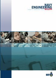
This computer-generated image shows the<br />
general characteristics of the <strong>Royal</strong> <strong>Navy</strong>’s<br />
Type 45 Destroyer. [Image from BAE Systems.]<br />
In line with the elimination of gearboxes, fluid couplings<br />
and CPPs, the RN also sees diesel engines as being high<br />
maintenance, unreliable machines and is keen to replace<br />
them with gas turbines. (This is probably due to their experience<br />
of diesel engines being limited to those manufactured<br />
within the UK. The RAN has had experience with<br />
diesel engines from many nations and found some to be<br />
quite reliable. IFEP will work just as well<br />
with diesel engines, or even with fuel<br />
cells, in place of gas turbines).<br />
The RN states that industry is developing<br />
the power electronics necessary for<br />
smaller and lighter controllers and considers<br />
that they will be available in time.<br />
Development work being pursued by<br />
the RN in conjunction with partners is<br />
the development of complex cycle<br />
cruise and harbour duty gas turbines<br />
and permanent magnet propulsion motors.<br />
The RN also sees the replacement of stored energy systems<br />
such as hydraulics and pneumatics by electrical systems<br />
as desirable due to improved reliability and practicality due<br />
to the stored energy available in the battery needed for<br />
MGO.<br />
The Future Carrier (CVF) would have two motors (similar<br />
to those of the Escort) per shaft and an increased power<br />
generator plant while the Future Attack Submarine (FASM)<br />
would also utilise some of the same electrical componentry.<br />
The carrier is one of the applications where the flexibility<br />
of electric propulsion can be exploited through the location<br />
of the propulsion gas turbines in the island superstructure.<br />
The Invincible class (CVS) in particular suffered from<br />
the loss of hangar space due to the intake and uptake<br />
ducting associated with the four Olympus gas turbines.<br />
Although the CVF is expected to be a larger vessel the space<br />
saving of Electric propulsion will allow a larger Carrier Air<br />
group for a given displacement.<br />
It is intended that the propulsion motors and large generators<br />
be a high voltage AC system and the ship services be<br />
on a medium voltage DC ring main. These two systems are<br />
interfaced by rectifier / inverter units enabling one system<br />
to supply the other. For example when a WR-21 is running,<br />
high voltage AC is supplied directly to the propulsion motors<br />
and DC to the ship services via the rectifiers. If the running<br />
machine fails then the battery will supply the DC ring<br />
main directly and the propulsion via the inverters. Additional<br />
redundancy is provided by having ship services arranged<br />
in zones; within each zone are two power supply<br />
The demise of Common New Generation Frigate (CNGF) was<br />
the latest in a long line of abortive efforts to replace the<br />
RN’s ageing Type 42 AAW destroyers and their GWS 30 Sea<br />
Dart area defence missile system. The proposed Type 43<br />
and Type 44 destroyer designs fell by the wayside by the<br />
early 1980s. The UK pulled out of the eight-nation NFR-90<br />
program in 1989 as a result of a perceived misalignment<br />
between the platform and weapon system; and the national<br />
Future Frigate program of the early 1990s was quickly subsumed<br />
into the Anglo-French Future Frigate program. This<br />
eventually became, with Italy joining in, the CNGF, also<br />
known as project Horizon.<br />
Following the demise of Project Horizon as the vehicle for<br />
the future escort, the UK <strong>Royal</strong> <strong>Navy</strong> is defining the requirements<br />
for a new anti-air warfare warship to replace its ageing<br />
Type 42 destroyers.<br />
As a national project, the likelihood of IFEP being adopted<br />
in the Type 45 is much greater, given the obvious satisfaction<br />
with the current Type 23 ships. The short timescale<br />
resulting from the delays due to the earlier projects will<br />
encourage the use of existing designs and concepts, includ-<br />
14
Naval <strong>Engineering</strong> Bulletin • June 2001<br />
ing IFEP. However, the need to place the ships in service may<br />
see the adoption of less advanced electrical technology than<br />
planned for in the IFEP program, and that proposed by the<br />
USN. Alstom’s most recent multi pole, fifteen phase AC<br />
motor appears more likely to be adopted than permanent<br />
magnet technology.<br />
Current USN Plans for the<br />
DD21<br />
The US <strong>Navy</strong> (USN) plans to introduce the<br />
first of 32 Zumwalt-class (DD 21) destroyers<br />
into service in Fiscal Year 2011 (FY11).<br />
The vessels, with a projected life of at least<br />
35 years, will replace Oliver Hazard Perryclass<br />
(FFG 7) frigates and Spruance-class<br />
(DD 963) destroyers. The design will also<br />
act as the basis for the CG 21 ‘air-dominance’<br />
cruiser, development of which will<br />
start in the next decade, that is intended<br />
to replace the Ticonderoga-class (CG 47)<br />
Aegis guided-missile cruiser.<br />
The DD 21 will employ electric drive, using<br />
an integrated power system (IPS). The<br />
commercial marine industry has already<br />
adopted such an approach for applications such as cruise<br />
liners, where it is known as the ‘Power Station’ concept. Until<br />
recently, the USN had ruled out the use of DC motor electric<br />
propulsion for combatants because of its inherent design<br />
limitations, which were generally agreed to be an<br />
output power of 5-6MW at 150-250rpm propeller speed.<br />
These ratings are well below the 15-20MW per shaft required<br />
by a typical surface warship. Another drawback was<br />
that, before about 1990, there were no AC variable-speed<br />
drives of adequate power and reliability that could be used<br />
as an alternative to DC drives.<br />
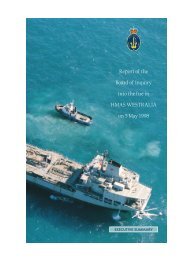
The US <strong>Navy</strong>’s proposed DD21 is a<br />
much more radical design than the<br />
Type 45 and this may be reflected in<br />
its propulsion technology.<br />
[Image from the DD21 “Blue Team”.]<br />
The use of DC power is an important part of this concept,<br />
for several reasons. The use of multiple sources provides<br />
uninterrupted power to user loads without the need for<br />
phase matching. This design approach also effectively separates<br />
propulsion power from ship’s service power. Naval user<br />
loads require power to a high standard, which cannot be<br />
provided directly from the propulsion bus. Other methods<br />
of providing this quality of separation were examined, but<br />
were found to be less desirable than DC distribution. They<br />
included the use of motor-generator sets, split distribution<br />
buses and filtering. Additional benefits stem from the fact<br />
that inverting DC to the appropriate frequency near the user<br />
loads limits the effects of electrical system disturbances,<br />
and eliminates the need for electromechanical switchgear.<br />
The two industry consortia competing to build DD-21—one<br />
led by Bath Iron Works of Maine, the other by Ingalls Shipbuilding<br />
of Mississippi—have both been striving to develop<br />
designs for IPS and electric drive for the new ship.<br />
The USN has placed heavy emphasis on reducing costs in<br />
terms of both acquisition and operations and support. Many<br />
of the savings will come from reductions in manning, since<br />
personnel historically account for about 60% of a ship’s lifecycle<br />
cost. The DD 21 is planned to have a crew of 95, including<br />
the helicopter detachment, compared with<br />
approximately 320 for the DDG 51. Additional berthing accommodation<br />
is also required for temporarily<br />
assigned personnel, such as an<br />
embarked commander and staff, together<br />
with special operations forces.<br />
The US <strong>Navy</strong> plans called for a choice between<br />
the two DD21 teams in April 2001.<br />
The selected DD 21 lead contractor will select<br />
the various constituents of the IPS on<br />
the basis of the technology available at the<br />
time. Candidates include power electronic<br />
building blocks, permanent-magnet motors,<br />
pulsed power systems, fuel cells, energy<br />
storage devices, and podded<br />
propulsion.<br />
The USN has investigated the Azipod, a commercial<br />
azimuthing propulsor. ABB, Kvaerner Masa-Yards and<br />
Fincantieri formed ABB Azipod Oy, a new company that<br />
will manage the business activities of the Azipod electric<br />
propulsion system. Under the agreement, ABB Industry will<br />
own 55 percent of the company, and Kvaerner and<br />
Fincantieri will each own 22.5 percent. ABB Azipod Oy commenced<br />
its activities in a new manufacturing facility in<br />
Helsinki, Finland.<br />
This type of podded propulsor has been investigated by the<br />
U.S.<strong>Navy</strong> for application to future vessels in the destroyer<br />
category. The Project Executive Officer of the DD21 project,<br />
as well as other USN representatives visited ABB Azipod and<br />
Kvaerner Masa Shipyards of Helsinki, Finland, in June 1998.<br />
The design, manufacture, and installation procedures of<br />
Azipod were discussed at length together with the associated<br />
hydrodynamic attributes leading to substantial gains<br />
in ship propulsive efficiency, turning-circle diameter, and<br />
crash-stop distance. The post-construction installation procedure<br />
of the Azipod was explained at the Kvaerner Masa<br />
Shipyards, where 14MW units were being installed on a<br />
twin-screw cruise ship.<br />
15
Naval <strong>Engineering</strong> Bulletin • June 2001<br />
Complex Cycle Gas Turbines<br />
The RN’s IFEP program, and to a lesser degree the USN’s IPS<br />
program, hinges on the development of complex cycle gas<br />
turbines, as they theoretically offer much greater fuel efficiency,<br />
especially at part loads, than do simple cycle machines<br />
and they promise similar fuel economy to a diesel.<br />
Other advantages are lighter weight than equivalent diesel<br />
engines and better atmospheric emissions without the need<br />
for secondary exhaust gas treatment, which could become<br />
a requirement for diesel engines in the future, particularly<br />
in Europe.<br />
The WR-21<br />
In December 1991 the USN awarded a design and development<br />
contract to a Westinghouse led team for an<br />
intercooled and recuperated gas turbine. The team members<br />
were: Westinghouse - prime contractor and system<br />
integrator; Rolls Royce - gas turbine design and development;<br />
AlliedSignal - recuperator and intercooler; and CAE<br />
Electronics - controls. The engine is intended as a replacement<br />
for the current simple cycle GE LM 2500 and as such<br />
has the same footprint although it is taller, as the recuperator<br />
sits on top of the engine, and it is considerably heavier.<br />
A US / UK Memorandum of Understanding (MOU) was<br />
signed in 1994 and a US / French MOU in 1995 to defray the<br />
developmental costs and obtain a wider market for the engine.<br />
Westinghouse’s defence interests were taken over by<br />
Northrop Grumman about 1995/6. Currently the engine is<br />
believed to be running successfully with further work being<br />
carried out on the recuperator design before production<br />
commences. Fuel consumption savings are so far not<br />
as high as expected.<br />
Significant fuel savings are claimed for the WR-21 compared<br />
to the LM 2500, but the LM2500 fuel consumption figures<br />
used in the comparison are higher than those claimed by<br />
General Electric themselves for the LM2500. While the WR-<br />
21 fuel consumption figures are claimed to be equal to a<br />
diesel, they are higher than many modern diesels, and still<br />
rise significantly at lower powers, not unlike the LM2500.<br />
Below 10% power, a saving of 57% against the LM2500 is<br />
claimed, but the actual specific fuel consumption figure is<br />
still three times that of a diesel at a similar power.<br />
The weight of the WR-21 in its enclosure is twice that of an<br />
LM2500, although the space occupied is similar, since the<br />
recuperator occupies what would be uptake space in a simple<br />
cycle turbine. A WR-21 would result in significant fuel<br />
savings, but with a penalty in weight and complexity. The<br />
weight penalty is lower than that incurred by additional<br />
diesel cruise engines, but the weight of auxiliary electric<br />
motors as used on the <strong>Royal</strong> <strong>Navy</strong> Type 23 would be in the<br />
same order of magnitude. This use of auxiliary electric drive<br />
in conjunction with an LM2500 may provide similar fuel<br />
savings without the additional complexity of the WR-21.<br />
GE’s past success in propelling USN Destroyers and Frigates<br />
would seem to suggest that the WR-21 is unlikely to be the<br />
only gas turbine selected for the DD-21 and its successors,<br />
regardless of its improved fuel economy. At least some of<br />
these vessels are likely to have the LM2500 or some derivative<br />
as main propulsion gas turbines.<br />
The <strong>Royal</strong> <strong>Australian</strong> <strong>Navy</strong><br />
The RAN has had quite successful experience of electric<br />
propulsion in non-combatant surface ships dating back to<br />
the Second World War. The Fleet Tugs SPRIGHTLY and RE-<br />
SERVE were obtained from a group built for the Admiralty<br />
under Lend Lease arrangements but these were similar to<br />
many contemporary USN vessels. This was the first use of<br />
electric propulsion in the RAN surface fleet and utilised<br />
General Motor’s diesels developed for locomotive use. The<br />
better known application was the survey ship MORESBY,<br />
which had three English Electric 16CSVM diesel engines<br />
driving two DC propulsion motors from the same manufacturer.<br />
Again, the equipment was developed from contemporary<br />
railway locomotive practice. The success and<br />
long life of MORESBY, in clear contrast to her conventionally<br />
powered half-sister COOK, influenced the selection of<br />
electric propulsion for the current hydrographic ships.<br />
Submarines<br />
The RAN has operated Oberon and Collins class diesel electric<br />
submarines. These submarines could be said to have<br />
an IFEP system as both the boat’s services and propulsion<br />
are supplied from the same batteries. However there is a<br />
difference in that the diesel generators recharge the batteries<br />
when the boats are on the surface or at schnorkel<br />
depth and never supply the load directly, unlike the proposed<br />
surface ship IFEP systems where the battery is used<br />
for backup only.<br />
Two 440-volt DC batteries with a large, twin armature, direct-drive<br />
DC motor on each propeller shaft supply the<br />
Oberon propulsion system. Variable speed is achieved by<br />
different groupings of batteries and armatures to give different<br />
speed ranges and within each range by varying the<br />
motors’ field current.<br />
Collins has two 440-volt DC batteries and a single twin armature,<br />
direct-drive DC motor weighing 87 tonnes. It has<br />
different groupings of batteries and armatures to achieve<br />
different speed ranges. To achieve its lowest speed range it<br />
uses some solid state electronics, namely a chopper to reduce<br />
the voltage to the motor.<br />
16
Naval <strong>Engineering</strong> Bulletin • June 2001<br />
In the tendering process for the new submarine project the<br />
German consortium offered a Siemens permanent magnet<br />
motor which at 46 tonnes was nearly half the weight of<br />
Collins’s conventional DC motor. This was new technology<br />
and would have offered a lead in to the more powerful<br />
motors needed for surface ships had the tender been successful.<br />
Hydrographic Ship<br />
The recently built Hydrographic<br />
Ships have electric propulsion and<br />
use commercial off the shelf<br />
(COTS) technology. There are two<br />
propeller shafts each with a 1200-<br />
rpm GEC Alsthom 1000 kW AC induction<br />
propulsion motor driving<br />
through a reduction gearbox. The<br />
two variable speed power supplies<br />
are 12 pulse diode series Pulse<br />
Width Modulated voltage source<br />
inverter through IGBT with 700 Hz<br />
fixed chopping frequency. There<br />
are four main diesel generator sets<br />
of 800 kW each; one 350 kW harbour generator set; one<br />
160 kW emergency generator set; three ship service transformers;<br />
two propulsion transformers; one main switchboard;<br />
one ship service switchboard; and one emergency /<br />
harbour switchboard. As well as the propulsion motors there<br />
is a 380 kW bow thruster with its variable speed drive, and<br />
four harmonic filters to isolate propulsion and bow thruster<br />
harmonics from the ship’s services. The relatively low power<br />
and relatively poor acoustic signature of the system, due<br />
to the geared drive, makes it unsuitable for an ASW frigate<br />
but it is an IFEP system.<br />
Lessons from History<br />
It now seems appropriate to consider some historical examples<br />
of electrically propelled major warships, and to look<br />
for any lessons learned. The US <strong>Navy</strong> has long been a supporter<br />
of electric drive for surface warships.<br />
The former collier Jupiter was converted to become the<br />
small aircraft carrier Langley (CV-1) which entered service<br />
in 1922. Two proposed battle cruisers survived the Washington<br />
treaty to be completed as the (nominally) 33,000 ton<br />
aircraft carriers Lexington (CV-2) and Saratoga (CV-3) in<br />
1927. They had four 3-phase 40,000 kVA 6250 volt turbogenerators<br />
driving eight 16,000 kW propulsion motors, two<br />
per shaft, for a top speed of 34 knots. It appears that all<br />
these early systems were variable frequency (without complex<br />
power electronics!) The speed of the steam turbine and<br />
thus the frequency of the directly coupled generator was<br />
varied, to give good speed control of the motors and ship.<br />
The USS Lexington was the USN’s second Aircraft Carrier<br />
and was one of the most powerful electrically powered<br />
ships in the world for its time. [Photo - US <strong>Navy</strong>.]<br />
(The frequency range included 60Hz, and the Lexington was<br />
used to supplement the city power supply in Bremerton<br />
during a drought when hydroelectric power was unavailable.)<br />
The Lexington and Saratoga played an important part in<br />
the Second World War, and both suffered considerable battle<br />
damage from bombs and torpedoes. While the electric<br />
propulsion allowed good subdivision of the hull and aided<br />
damage control, the high voltages required for the high<br />
power resulted in a hazard not<br />
present in a conventional ship.<br />
The Lexington was lost on 8 May<br />
1942 during the battle of the Coral<br />
Sea, after being hit by two bombs<br />
and two air launched torpedoes.<br />
One torpedo hit forward, adjacent<br />
to the aviation gasoline (avgas)<br />
tanks. Although these tanks were<br />
protected by water ballast tanks<br />
outboard, the shock ruptured the<br />
bulkhead seams and allowed<br />
avgas vapour to escape. This eventually seeped into the forward<br />
motor generator room, where 3125 volts was reduced<br />
to 110 volts for domestic services and lighting, resulting in a<br />
series of explosions and fires that effectively destroyed the<br />
ship. It must be admitted that the avgas was the problem,<br />
and it could easily have been ignited by other than an electrical<br />
source in a different vessel.<br />
The somewhat luckier Saratoga was hit by a submarine<br />
launched torpedo on 31 August 1942, and the shock was<br />
such that a “shockproof” normally open breaker momentarily<br />
closed. This short-circuited the two operating (of four)<br />
main turbo alternators, resulting in an electrical explosion<br />
causing the protective breakers to operate and resulted in<br />
a complete loss of propulsive power. While power was<br />
quickly restored, the damage and carbon tracking caused<br />
by the previous explosion caused two more explosions in<br />
the high-tension circuitry as efforts were made to get under<br />
way. The ship was taken in tow for three hours while<br />
repairs were carried out. The ship did not return to normal<br />
propulsion conditions until 4 September, although the hull<br />
damage caused by the torpedo resulted only in the flooding<br />
of one boiler room (of sixteen) and the partial flooding<br />
of another.<br />
It should not be forgotten that the high voltages and currents<br />
required for electric propulsion pose an additional<br />
hazard over that of normal ship electrical distribution, particularly<br />
after battle damage, and this can pose an additional<br />
risk for inflammable fuels and chemicals.<br />
17
Naval <strong>Engineering</strong> Bulletin • June 2001<br />
A Comparison of New and<br />
Current Technology Propulsion<br />
Motors<br />
In the article, some of the technologies expected to assist in<br />
reducing the weight involved in electric propulsion have<br />
been discussed. To indicate the magnitude of the weight<br />
savings, the following example is provided. At present, it<br />
seems likely that the current generation of technology will<br />
be used in the RN Type 45, and possibly also in the USN<br />
DD21.<br />
The large size of the Alstom conventional<br />
technology 19 MW propulsion<br />
motor is reflected in its weight of 117<br />
tonnes. [Photo from Alstom.]<br />
A 19 MW Destroyer Propulsion Motor<br />
Current AC Permanent High Temperature<br />
Variable Frequency Magnet Superconductor<br />
Rating 19 MW at 150 rpm 19 MW at 100rpm 19 MW at 100 rpm<br />
Outside Diameter 4.5 m x 4.0 m 4.2 m 2.3 m<br />
Axial Length 4.8 m 1.2 m 1.0m<br />
Motor Weight 117 tonnes 50 tonnes 19 tonnes<br />
Design Alstom Kaman American<br />
Electromagnetic<br />
Superconductor<br />
Only the Alstom motor has been built, as part of the US<br />
<strong>Navy</strong> Electric Propulsion Full-Scale Development program.<br />
Kaman has built smaller motors for marine propulsion, up<br />
to 3000 hp (2240 kW) at 300 rpm. American Superconductor<br />
are currently constructing experimental motors of 200<br />
hp and 1000 hp.<br />
(Data from Papers presented at Naval Symposium on Electric<br />
Machines, Annapolis Maryland October 26-29 1998)<br />
About the Author<br />
Peter Clark works for the Directorate of Naval Platform<br />
Systems within <strong>Navy</strong> Systems Branch, and is the Project<br />
Liaison Officer for Amphibious and Afloat Support<br />
Projects. He has previously worked with Naval Aviation<br />
<strong>Engineering</strong>, the RAAF Tactical Fighter Project and the<br />
Guided Missile Frigate Project.<br />
The General Atomics permanent magnet motor promises a smaller<br />
and lighter motor, but requires additional cooling equipment for<br />
the superconducting elements. No full size motor has yet been built.<br />
[Photo - General Atomics.]<br />
18
Naval <strong>Engineering</strong> Bulletin • June 2001<br />
A schematic diagram of the proposed Type 45 IFEP propulsion solution - Alstom<br />
19
Naval <strong>Engineering</strong> Bulletin • June 2001<br />
Managing <strong>Engineering</strong> & Supply<br />
Categories<br />
By Warrant Officer Bruce Tunnah<br />
As the RAN reshapes for the new century with the introduction<br />
of new platforms and material capability, along with<br />
resized personnel ceiling, <strong>Navy</strong> is presented with a significantly<br />
altered environment for workforce management.<br />
Additionally, the day to day issues involved in the management<br />
of categories require sound specialist knowledge,<br />
which is both platform and equipment specific.<br />
The Directorate of Naval Professional Requirements (<strong>Engineering</strong><br />
and Logistics) (DNPR (E&L)), headed by CAPT Craig<br />
Kerr, are the <strong>Engineering</strong> and Supply Category Sponsors and<br />
they make policy to manage the category size, and capabilities.<br />
These requirements are entered into the total Naval<br />
Workforce Plan and form the basis for the management<br />
of our people’s careers.<br />
The Role of the Category<br />
Sponsor<br />
The role of the category sponsor is wide-ranging. A primary<br />
role is to liaise with all elements of the navy workforce<br />
pipeline, acting as a ‘system manager’; tuning the pipeline<br />
to achieve the Naval Workforce Plan outcomes in the most<br />
successful manner possible. Further, category sponsors<br />
identify potential problem areas, analysis and develop plans<br />
to resolve them.<br />
In order to fulfil their role, the category sponsors must maintain<br />
currency with the Fleet and the issues effecting our<br />
people. They also use data from a variety of sources to assist<br />
in identifying problem areas and support the development<br />
of Workforce planning to provide data on total<br />
numbers. This enables the Directorate of Sailors Career<br />
Management (DSCM) and Directorate of Naval Officers’<br />
Posting (DNOP) to undertake the day to day management<br />
according to category sponsor guidelines.<br />
What Does all this Mean to<br />
Me?<br />
For Technical and Supply personnel, DNPR (E&L) is your<br />
voice in Canberra, and your adviser regarding category<br />
sponsorship issues. DNPR (E&L) is also involved in:<br />
• Pay cases to go before the DFRT,<br />
• Competency Standards in consultation with the relevant<br />
training authorities,<br />
• Civil accreditation,<br />
• Career progression profiles,<br />
• Changes to the Category Structure, and<br />
• Providing direction to the posters on category specific<br />
posting issues. Etc<br />
Taking into account all of the above, Category Sponsors are<br />
your ‘one stop shop’ when it comes to confirming any policy<br />
issues related to technical & supply categories. If you have<br />
a question on the application of the policy talk to DSCM or<br />
DNOP first. If you are still unhappy or have some good ideas,<br />
call DNPR’s personnel line-up.<br />
Any questions regarding Technical and Supply category<br />
sponsorship in the RAN can be directed to the DNPR(E&L)<br />
personnel below:<br />
Marine <strong>Engineering</strong><br />
ADNPR (ME) (ME Category Sponsor)<br />
CMDR Andy HAMILTON 6266 4793 CP4-7-122<br />
Andy.Hamilton@cbr.defence.gov.au<br />
SO Marine Technical<br />
CPOMT Danny Chouffot 6266 4211 CP4-7-130<br />
Danny.Chouffot@cbr.defence.gov.au<br />
SO Marine Technical 2<br />
CPOMT Gary LEISFIELD 6266 4071 CP4-7-131<br />
Gary.Leisfield@cbr.defence.gov.au<br />
Weapons <strong>Engineering</strong><br />
ADNPR (WE) (WE Category Sponsor)<br />
CMDR Richard JONES 6266 3048 CP4-7-123<br />
Richard.Jones@cbr.defence.gov.au<br />
SO Electronic Technical<br />
CPOET Antenor GORDON-COOKE 6266 2704 CP4-7-133<br />
Antenor.Gordon-Cooke@cbr.defence.gov.au<br />
20
Naval <strong>Engineering</strong> Bulletin • June 2001<br />
SO Electronic Technical<br />
WOET Jacqui BRYANT 6266 3489 CP4-7-134<br />
Jaqui.Bryant@cbr.defence.gov.au<br />
Aviation <strong>Engineering</strong><br />
ADNPR(AE) (AE Category Sponsor)<br />
CMDR Darryl VARCOE 6266 2097 CP4-7-124<br />
Darryl.Varcoe@cbr.defence.gov.au<br />
SO Aviation Technical<br />
WOAT Bruce TUNNAH 6266 4584 CP4-7-136<br />
Bruce.Tunnah@cbr.defence.gov.au<br />
SO Aviation Technical<br />
POATV Robert MILLER 6266 2570 CP4-7-137<br />
Robert.Miller@cbr.defence.gov.au<br />
<strong>Engineering</strong> Employment and Training<br />
ADNPR (<strong>Engineering</strong> Employment and Training)<br />
LCDR Clyde WHEATLAND 6266 3495 CP4-7-139<br />
Clyde.Wheatland@cbr.defence.gov.au<br />
SO <strong>Engineering</strong> Employment and Training<br />
Mr Rob ALLARD 6266 4110 CP1-4-B2<br />
Rob.Allard@cbr.defence.gov.au<br />
Supply<br />
ADNPR(SU) (SU Category Sponsor)<br />
CMDR Paul KINGHORNE 6266 4159 CP4-7-093<br />
Paul.Kinghorne@cbr.defence.gov.au<br />
SO ILS Policy<br />
LCDR Rory MCCARTNEY 6266 3281 CP4-7-128<br />
Rory.McCarthy@cbr.defence.gov.au<br />
SOTP (Transition Planning)<br />
LEUT Nathan ROBB 6266 4154 CP4-7-129<br />
Nathan.Robb@cbr.defence.gov.au<br />
SOSS (Ship Support)<br />
LEUT Stephanie CANNON 6266 3281 CP4-7-104<br />
SO Professional Development (SU PQ Sponsor)<br />
LCDR Graham FALLS 6266 4196 CP4-7-102<br />
Graham.Falls@cbr.defence.gov.au<br />
A/SO Afloat Support (SN Category Sponsor)<br />
WOSN Allan THOMAS 6266 2500 CP4-7-100<br />
Allan.Thomas@cbr.defence.gov.au<br />
A/SO Ship Support (STD Category Sponsor)<br />
WOSTD Carl ANDERSON 6266 4157 CP4-7-103<br />
Carl.Anderson@cbr.defence.gov.au<br />
A/SO Transition Planning (CK Category Sponsor)<br />
WOCK William MATTHEWS 6266 63064 CP4-7-127<br />
William.Matthews@cbr.defence.gov.au<br />
(WTR Category Sponsor)<br />
CPOWTR Kim VAN-WETERING 6266 3586 CP4-5-175<br />
Kim.Van-Wetering@cbr.defence.gov.au<br />
SOAS (SO Afloat Support)<br />
LCDR Christian BRETMAISSER 6266 2483 CP4-7-105<br />
Christian.Bretmaisser@cbr.defence.gov.au<br />
21
Naval <strong>Engineering</strong> Bulletin • June 2001<br />
FIMA Sydney Circuit Card Assembly—Test<br />
and Repair Facility<br />
By LEUT Kirsten DAVIS, RAN<br />
What is the CCA-TRF?<br />
Test Equipment<br />
The Fleet Intermediate Maintenance Activity - Sydney<br />
(FIMA-S) is responsible to Commander Fleet Maintenance<br />
(CFM) for providing intermediate maintenance assistance<br />
for rectification of defects beyond the normal capacity or<br />
capabilities of ships’ staff.<br />
Within FIMA-S is the Circuit Card Assembly Test and Repair<br />
Facility (CCA-TRF), commonly referred to as the ‘FIMA<br />
PCB Lab’. It is the primary facility for Intermediate Level<br />
test and repair of Circuit Card Assemblies (CCAs).<br />
Capabilities of the CCA-TRF<br />
Last year, the FIMA CCA-TRF received approximately 200<br />
analogue and digital Circuit Card Assemblies (CCAs) for testing<br />
and repair. Most of these CCAs came from the Logistics<br />
Support Organisation (LSA), directly off ships (on a Maintenance<br />
Control Record (TM200) basis) and from system trainers<br />
on Garden Island. Recently, the lab has also undertaken<br />
an Ordnance Alteration (ORDALTS) and Report of Defective<br />
Material or Design (TM179) action for the LSA and Mobile<br />
Operational Technical Unit (MOTU).<br />
Located on Level 3 in Building 79 at Fleet Base East, the<br />
CCA-TRF also operates as a ‘drop in’ centre offering troubleshooting<br />
assistance for urgent repair work for ships<br />
alongside.<br />
There are over 1400 Test Program Sets (TPSs) that support<br />
CCAs from numerous systems including Mk-92 Fire Control<br />
System, Mark 15 Close-In<br />
Weapon System (CIWS), SPS-49 Radar<br />
and Peripheral Control Systems.<br />
The CCA-TRF uses these test programs<br />
to diagnose and pinpoint the<br />
location of possible components that<br />
may be causing the CCA to fail.<br />
Two types of automatic test stations are currently used by<br />
the CCA-TRF to functionally test the CCAs. These are the<br />
M3-ATS and the Genrad 2225. Both these stations run test<br />
programs that determine whether or not a CCA is serviceable.<br />
If the CCA is non-serviceable a list of possible faulty<br />
components is generated which are then tested individually<br />
to isolate the faulty components.<br />
The M3 Automatic Test Station is a freestanding unit that<br />
contains a suite of VXI and GPIB instruments. All TPSs for<br />
the M3-ATS are developed in TestBasic and are used to control<br />
the instruments to exercise the CCA with predetermined<br />
stimuli and then compare the measured response against<br />
the expected response.<br />
The RAN’s main method of in circuit testing is the GenRad<br />
2225. The Genrad 2225 is a digital circuit tested with limited<br />
analogue capability. It was first introduced in to the<br />
RAN in the early 1980s and has proved to be a reliable and<br />
effective test station. TPSs that run on this station can isolate<br />
to individual component level.<br />
FIMA Sydney CCA-TRF is the also only designated <strong>Australian</strong><br />
Defence Force repair agent for the Genrad. The USN no<br />
longer supports the Genrad or by Genrad Inc. and as the<br />
predominant user of the Genrad, the RAN provides user<br />
training and maintenance, repair and calibration actions on<br />
the Genrad for both the RAAF and the Army.<br />
Following fault detection on an automatic test station, diagnostic<br />
tools are used to further isolate the faulty component.<br />
The RAN’s most commonly<br />
used diagnostic tools are the<br />
Huntron range of instruments including<br />
the Huntron 5100DS. The<br />
5100DS interfaces with a computer,<br />
where the signature of a component<br />
being tested is compared with<br />
a signature stored in a computer<br />
database. These stored signatures<br />
are part of a signature set for the<br />
entire CCA, which is known as a<br />
22
Naval <strong>Engineering</strong> Bulletin • June 2001<br />
RAN Gold Disk. RAN Gold Disks are developed by the CCA-<br />
TRF and contractors.<br />
If a RAN Gold Disk has not been developed for the CCA then<br />
the technician may use the Huntron Tracker 2000. The<br />
Tracker 2000 works on the same principle as the 5200DS<br />
but does not interface with a computer. Instead, technicians<br />
compare suspect components on a faulty CCA with those<br />
on a known serviceable CCA. Either way, both instruments<br />
are powerful fault finding tools.<br />
Repair<br />
When a faulty component has been isolated a technician<br />
replaces it. All technicians working at the CCA-TRF gain<br />
their qualifications from HMAS Albatross, Nowra and repair<br />
to the ANSI IPC A 610, J-STD-001 Standard. Once a component<br />
has been replaced, the CCA is functionally tested<br />
and if serviceable, it can be repackaged and sent back to<br />
the customer. In addition to repairing faulty CCAs the CCA-<br />
TRF are also capable of repairing damaged Printed Circuit<br />
Boards (PCBs), from through hole repair to track replacement.<br />
The Pie chart represents the percentage of CCCAS received<br />
that were repaired and other percentage of CCAs that were<br />
found to be serviceable after initial testing. The high percentage<br />
of ‘No Fault Found’ CCAs which would ordinarily<br />
be sent to commercial contractors for repair indicates the<br />
significant cost benefits the CCA-TRF provides.<br />
Maintenance and Retrieval<br />
Data<br />
All CCAs received by the CCA-TRF for repair are added to a<br />
database known as SupportTrack. SupportTrack was specifically<br />
designed for the CCA-TRF and keeps a detailed<br />
history of all CCAs that pass through the establishment. It<br />
tracks inventory and CCA repair, places automatic orders<br />
and lists all TPSs. SupportTrack can also present vital statistics<br />
about the CCA-TRFs performance; from the number<br />
of CCAs repaired to the number of CCAs from each customer.<br />
The FIMA Sydney CCA-TRF website provides greater visibility<br />
to the support organisation of the capability of the<br />
laboratory and access to repair specifications and standards.<br />
The web site is accessed through the Centre for Maritime<br />
<strong>Engineering</strong> website at http://defweb.cbr.<br />
defence.gov.au/navycme/fimaccatrf/home.htm.<br />
Daily operation of the FIMA CCA-TRF is overseen by POET<br />
Adam Smith (Ph: 02 9359 3670) with ATE and TPS acquisition<br />
and support managed by LEUT Kirsten Davis of CME.<br />
About the Author<br />
Lieutenant Kirsten Davis joined the <strong>Navy</strong> in 1995 as a WE<br />
officer through the Undergraduate Scholarship program. I<br />
completed my degree at the end of 1997 and then commenced<br />
initial entry at HMAS CRESWELL and application course at<br />
HMAS CERBERUS.I received my WECC in September 1999,<br />
having completed my AWEEO time. I then posted to the Centre<br />
for Maritime <strong>Engineering</strong> (formally MMES) as the Weapon<br />
Systems Engineer where I was responsible for support of Automatic<br />
Test Equipment for the RAN Surface Fleet. In April<br />
2001, I posted to HMAS TOBRUK where I am currently the<br />
Deputy <strong>Engineering</strong> Officer.<br />
23
Naval <strong>Engineering</strong> Bulletin • June 2001<br />
ADF Aerospace <strong>Engineering</strong><br />
Professional Development<br />
By CMDR Darryl Varcoe, RAN (Assistant Director <strong>Navy</strong> Professional Requirements - Aviation <strong>Engineering</strong>)<br />
On 18 Oct 00, the Chiefs Of Staff Committee endorsed recommendations<br />
from the Senior Review Team report on improvements<br />
to the ADF Aviation capability. An endorsed<br />
recommendation was “Air Force’s <strong>Engineering</strong><br />
Sustainability Project be widened to an ADF Aerospace <strong>Engineering</strong><br />
Sustainability Project”. A subsequent project was<br />
initiated by Chief of Air Force to develop and implement<br />
long-term strategies for improved retention of Air Force’s<br />
Aerospace Engineers. The three key areas were:<br />
• Remuneration<br />
• Career Management, and<br />
• Professional Development which is designed to allow<br />
Aerospace Engineers to remain abreast of current<br />
aviation technology and further develop their<br />
technology management expertise, particularly with<br />
the continuing introduction of state-of-the art<br />
weapon systems.<br />
As part of the project, Air Force also identified four key initiatives<br />
for professional development of its Aerospace Engineers:<br />
• Dedicated full-time civil schooling<br />
• Short courses<br />
• Seminars<br />
• Professional recognition.<br />
A short course that contributes towards a Masters Degree<br />
is being developed by ADFA and an agreement has been<br />
signed with IEAust for a Graduate Development Program<br />
(GDP). Through completion of the Competency Based Assessment<br />
system administered by IEAust, tertiary qualified<br />
engineers can gain accreditation as Chartered Professional<br />
Engineers (CPEng) and registration on the National Professional<br />
Engineers Register (NPER). Non-tertiary qualified Engineers<br />
(AD(T) or equivalent) can gain accreditation as<br />
Chartered <strong>Engineering</strong> Officers (CengO).<br />
As all ADF Aerospace Engineers<br />
perform equivalent<br />
functions and require<br />
continuing professional<br />
development to remain<br />
current with aerospace<br />
technology and management<br />
skills, it was proposed<br />
that the three services adopt equivalent initiatives to<br />
ensure equity differences do not spread further between<br />
Air Force and the smaller categories within <strong>Navy</strong> and Army.<br />
CN has endorsed a similar program for <strong>Navy</strong> to that being<br />
conducted by the RAAF for the development of Aerospace<br />
Engineers. This initiative aligns with strategies identified<br />
for <strong>Navy</strong> Key Result Area 10: Learning organisation, by cultivating<br />
the intellectual capital of its Aerospace Engineers.<br />
The precedence set by this initiative may cause a flow-on<br />
to ME and WE stream Officers. Negotiations between<br />
DNPR(E&L) and IEAust will commence on 1 Jun 01 for participation<br />
in a similar program for MEO and WEEOs.<br />
This education is suited to ensuring that <strong>Navy</strong> continues to<br />
be an ‘informed customer’ with access to the latest technological<br />
advances. Directorate of Naval Personnel Requirements<br />
(<strong>Engineering</strong> & Logistic) will be responsible for<br />
defining detailed professional development requirements,<br />
coordinating the program and liaising with Air Force whilst<br />
DGNPT will be responsible for management of officers<br />
through full-time schooling. POC for DNPR (E&L) on this<br />
matter is CMDR Darryl Varcoe on (02) 62662097 or e-mail<br />
darryl.varcoe@cbr.defence.gov.au<br />
24
Naval <strong>Engineering</strong> Bulletin • June 2001<br />
Professional Engineers in the<br />
<strong>Royal</strong> <strong>Australian</strong> <strong>Navy</strong><br />
By LEUT Robert Elphick, RAN<br />
If, as a graduate of a four-year engineering degree, I was<br />
employed in a civilian engineering practice, in many instances<br />
I would be encouraged, during the years following<br />
graduation, to be part of a program which would develop<br />
and extend the foundations of engineering knowledge laid<br />
at university 1 . This is not the case in the RAN. While there is<br />
a program for the Continual Professional Development<br />
(CPD) of engineers it is pitched at an intellectual level far<br />
below university engineering and could not be said to extend<br />
or develop the foundations of engineering knowledge<br />
laid at university. And where knowledge is not put into practice<br />
and developed, it is often lost.<br />
My purpose in contributing this article to the Naval <strong>Engineering</strong><br />
Bulletin is to provoke discussion on the training progression<br />
of the professional engineers 2 in the RAN. Since all<br />
training should be aimed at developing an officer for future<br />
employment, out of this may flow discussion on the<br />
role of the Naval Engineer and the training required to build<br />
this type of person.<br />
My thinking in this matter was stimulated through an article<br />
published by IEAust on the topic of professional practice<br />
3 . The article discussed the terms Cosmopolitan and<br />
Local with respect to one’s profession and used these terms<br />
to describe a professional person’s disposition regarding his<br />
career. A person valuing themselves (for want of a better<br />
expression) primarily in relationship to his immediate work<br />
place and organisation is described as having a strong local<br />
disposition. A person with a highly cosmopolitan disposition<br />
sees himself primarily in relationship to his profession.<br />
Most junior naval engineers posted to sea going vessels will<br />
very soon develop a strong local disposition. This is not surprising<br />
given that they are required to work in a close team<br />
with other officers, the large majority of whom are not engineers.<br />
The highly operational focus of a sea-going billet,<br />
together with the many collateral tasks (divisional and<br />
whole ship) is not at all conducive to the consolidation and<br />
extension of the foundations laid during the engineering<br />
degree. Consequently in this environment a junior officer<br />
will operate (and see themselves) more as a member of the<br />
Profession of Arms and develop more as a Naval Officer than<br />
they will as an Engineer.<br />
The situation is somewhat similar when the young engineer<br />
is then posted to a shore establishment in that loyalty<br />
to, and teamwork with, officers of different specialisations<br />
remain central tenets of the work. However, a shore job<br />
generally has a lesser operational focus and this factor, combined<br />
with the opportunity to work in an area with a larger<br />
percentage of engineers, increases the scope for a greater<br />
focus on purely engineering matters. While this allows an<br />
engineer to hold a slightly more cosmopolitan disposition<br />
than what he or she would hold at sea, the complexity of<br />
engineering practiced is still well below, or at least of a vastly<br />
different type, to what they will have studied at university.<br />
Even ashore there is no consolidation or extension of the<br />
skills gained at university.<br />
Have we decided that many of the specialised skills gained<br />
during university are not required of RAN engineers? If so,<br />
should there be a greater emphasis on management skills<br />
in the engineering degrees offered at the <strong>Australian</strong> Defence<br />
Force Academy? Should units be introduced at the Defence<br />
Force Academy, which deal with “operations engineers”<br />
related competencies (eg. configuration management,<br />
maintenance management, terotechnology, quality management,<br />
technical administration, and methods of performance<br />
analysis, environmental issues)? Could we better<br />
employ our young engineers? By not employing and developing<br />
their university learnt skills, are we contributing<br />
to retention problems?<br />
1 The end result of this program may be gaining status as a Certified Professional Engineer (CPEng) under the auspices of the Institution of Engineers,<br />
Australia (IEAust).<br />
2 A Professional Engineer, according to IEAust, is a graduate of a four-year engineering degree from a recognised university.<br />
3 Key Competencies in <strong>Engineering</strong> Practice Part A Chapter 1 p12 by Prof B. Lloydd, IEAust, 1999<br />
25
Naval <strong>Engineering</strong> Bulletin • June 2001<br />
I am in no doubt that the experience I have gained during<br />
my sea postings as a WE officer has developed my understanding<br />
of engineering practice. However, I have difficulty<br />
articulating exactly how this engineering relates to the<br />
majority of what I studied at university. Furthermore, I<br />
would have to admit that a lot of what I studied at university,<br />
because it has not been consolidated during the intervening<br />
years, is very faint.<br />
About the Author<br />
Lieutenant Robert Elphick BE (Elec) Hons. graduated from<br />
the <strong>Australian</strong> Defence Force Academy in 1994 and completed<br />
his WECC on HMAS Brisbane in 1996. He served as a Systems<br />
Engineer Officer in HMAS HOBART and is currently DWEO<br />
of HMAS BRISBANE. His shore postings have included CDSC<br />
and the Tactical Development and Analysis Group (TDAG),<br />
MHQ.<br />
I understand there is discussion in progress to determine<br />
how the cumulative experiences of a WE Officer on gaining<br />
their CQ may make him or her eligible to apply for recognition<br />
as a Certified Professional Engineer with IEAust. I<br />
think such an arrangement would greatly improve the vision<br />
of young naval engineers. In many cases the extra<br />
study required to be eligible for to gain CPEng would be<br />
accepted as a challenge.<br />
What do you think?<br />
Editor’s Note: Refer to article by CMDR Varcoe (page 24).<br />
26
Naval <strong>Engineering</strong> Bulletin • June 2001<br />
DNOP NEWS<br />
By LCDR Michael SIMPSON, RAN<br />
Enhancement of DNOP<br />
Engineers Career Management<br />
Section<br />
One outcome of the PERSAT and CN’s Leadership conference<br />
last year was that an additional position has been created<br />
at DNOP for management of junior <strong>Engineering</strong> Officer<br />
careers. This enhancement is aimed at providing a better<br />
service to officers by reducing the number of personnel<br />
managed by each position.<br />
After being gapped for some time the new position has been<br />
filled and from 23 April 2001 the cell was re-organised as<br />
follows:<br />
• DNOP Staff Officer <strong>Engineering</strong> 1 (SOE1, LCDR Mike<br />
Simpson) is responsible for career management of<br />
all <strong>Engineering</strong> Officers of LCDR Rank and all LEUTs<br />
possessing an <strong>Engineering</strong> Charge Qualification.<br />
• DNOP Staff Officer <strong>Engineering</strong> 2 (SOE 2, LEUT<br />
Andrew Payne) is responsible for all other <strong>Engineering</strong><br />
Officers.<br />
• <strong>Engineering</strong> officers who are still studying or as yet<br />
have not commenced the appropriate application<br />
course will continue to be managed by Staff Officer<br />
Undergraduates until commencement of that<br />
course.<br />
Introduction of the New Performance Appraisal System<br />
Defence has been developing a new tri-service performance<br />
appraisal system for sailors and officers since 1998. The introduction<br />
of the new system means that everyone in the<br />
ADF will participate in the one scheme rather than having<br />
a number of different systems that can cause confusion<br />
when people from other services are involved in the appraisal<br />
process.<br />
operates through Web Forms and has been developed to<br />
interface directly with Defence’s new Human Resources<br />
system, PMKEYS. For those who don’t have access to Web<br />
Forms, such as those on board ship, it will be available<br />
through your local area network rather than through Web<br />
Forms. The forms can be used as hard copy versions where<br />
they are not available electronically.<br />
In many respects the new system is not that different from<br />
the PERS1 and PR5 systems. It is designed to assess your<br />
performance and potential and will be used by DNOP and<br />
DSCM for posting, promotion and development purposes.<br />
What it does do is formalise a number of processes that<br />
were under utilised by <strong>Navy</strong>. At the start of a new performance<br />
cycle, you will be required to complete a Preliminary<br />
Review of Performance, which provides the opportunity for<br />
you and your assessor (supervisor, HOD or CO) to set goals<br />
for the forthcoming year. About half way through the performance<br />
cycle, you will have the opportunity to review<br />
your performance with your supervisor and receive feedback<br />
on the goals you have set. At the end of the cycle, you<br />
will be assessed on your overall performance throughout<br />
the reporting period, just as you have been in the past. However,<br />
now you will have an improved method of seeking<br />
changes to your annual or bi-annual assessment if you are<br />
not satisfied with it through an enhanced representation<br />
process.<br />
A number of signals have been issued regarding the <strong>Navy</strong><br />
specific policy and the transition from PERS1s and PR5s to<br />
the new system. These signals and further information on<br />
the new system are available on the DNOP and DSCM Web<br />
Sites (http://defweb.cbr.defence.gov.au/dpedscm and<br />
http://defweb.cbr.defence.gov.au/dpednop) or by contacting<br />
in DNOP, CMDR Pam Price (pam.price@cbr.<br />
defence.gov.au) and in DSCM, LCDR Tony Franklin<br />
(anthony.franklin@cbr.defence.gov.au)<br />
The new system will be available for all <strong>Navy</strong> personnel from<br />
April this year. It has been developed to improve the way<br />
we assess performance in the ADF. It makes use of the most<br />
up to date technology available and has been designed with<br />
future improvements in mind. The appraisal instrument<br />
27
Naval <strong>Engineering</strong> Bulletin • June 2001<br />
Revised Officers Selective<br />
Promotion System<br />
Introduction<br />
The current Officers Selective Promotion System has been<br />
operating for a number of years and has been supported<br />
PR 5 performance appraisal system and personnel data<br />
provided through NPEMS. The introduction of the ADF Officers<br />
Performance Appraisal System (AOPAS) and PMKEYS<br />
in 2001 has provided the impetus for <strong>Navy</strong> to review the promotion<br />
system. In doing so CN has directed DNOP to undertake<br />
a full review of the promotion system with a view<br />
to fitting it into a more holistic career management continuum.<br />
During 2000 a review was undertaken. Input received from<br />
the officer community showed a common perception that<br />
the current system unduly relies on Promotion Board members<br />
knowledge of individuals and Board members taking<br />
on an advocacy role for those for whom they have Section<br />
6 responsibility.<br />
The review team developed proposals for a revised promotion<br />
system, which were cleared by CNSAC in December<br />
2000. Detailed development of the various components of<br />
the system is currently underway and <strong>Navy</strong> will complete<br />
transition to the new system in December 2002.<br />
Key Components of the<br />
System<br />
There are seven key components of the Revised Officers’<br />
Selective Promotion System:<br />
• The development of published Selection Criteria<br />
upon which to base promotion decisions.<br />
• Qualification Based Boards (QBB) which replace<br />
Command based mini-boards.<br />
• A Career Advancement Board (CAB) which not only<br />
considers promotion but can also address other career<br />
development issues.<br />
• The opportunity for individuals<br />
to have input to the QBB<br />
and CAB.<br />
• More meaningful feedback on<br />
career development issues, not<br />
just promotion prospects,<br />
which is the current case.<br />
• Introduction of a Positive Career<br />
Management (PCM) system<br />
for selected officers.<br />
• One promotion seniority date.<br />
DNOP <strong>Engineering</strong> Staff Officers, LEUT Andrew<br />
Payne and LCDR Michael Simpson<br />
It is within these components that development work continues<br />
prior to publication of the detailed policy in ABR 6289<br />
in the latter part of 2001/early 2002. The following paragraphs<br />
provide a brief explanation of the key components<br />
of the system as they currently stand.<br />
Selection Criteria<br />
A requirement of the new system is that it be more objective<br />
and transparent. This is partially achieved by having<br />
enduring selection criteria that are known by the officer<br />
community and form the basis of promotion decisions. The<br />
selection criteria are yet to be fully developed and agreed<br />
by CNSAC. They will vary across the ranks and PQs however,<br />
for the purposes of equity and assessments across a<br />
PQ they will be kept as comparative as possible. It is probable<br />
that a weighting process will be applied to the selection<br />
criteria and this too will need to vary across the ranks.<br />
Proposed selection criteria endorsed by CNSAC in late 2000<br />
for further development were PQ Experience and Currency,<br />
Current Performance, Past Performance, Education and<br />
Qualifications, Command and Charge Experience, Breadth<br />
of Experience and Future Potential. While these criteria are<br />
fairly generic the expectations within each and the weighting<br />
would vary with rank and PQ.<br />
Qualification Based Boards (QBB)<br />
QBBs are PQ based boards that will assess all officers of a<br />
particular rank and PQ against the selection criteria. The<br />
prime task of the QBBs will be to produce an order of merit<br />
that the CAB will use to guide them in making personnel<br />
management decisions, including promotion decisions and<br />
development recommendations (. A database will be used<br />
to record the assessments, apply weightings and produce<br />
an order of merit. Benefits of the QBB process is that the<br />
members have detailed knowledge of PQ requirements and<br />
can equally represent all officers under consideration. In<br />
addition to producing an order of merit for the CAB the QBB<br />
can make other career development recommendations to<br />
the CAB and DNOP. The QBB will not be privy to promotion<br />
vacancy information when creating its order of merit. QBB<br />
members will normally be two ranks above those officers<br />
they are assessing, of at least CAPT rank and cannot also<br />
be a member of the CAB. The proposed<br />
QBB structure and composition<br />
is attached below.<br />
Career Advancement<br />
Board (CAB)<br />
There will be one CAB that meets to<br />
consider each rank. The CAB will<br />
comprise all, or a subset of, <strong>Australian</strong><br />
based RADMs and the Systems<br />
Commander. They have the best<br />
knowledge of <strong>Navy</strong>’s corporate re-<br />
28
Naval <strong>Engineering</strong> Bulletin • June 2001<br />
quirements and will be provided with promotion vacancy<br />
data. The CAB will not only make promotion recommendations<br />
to CN. They will also consider other career management<br />
issues such as PCM, extension of appointments<br />
and MIER and can make specific career development recommendations<br />
to DNOP.<br />
Individual Input<br />
It has been recognised that a number of officers want to<br />
have some input to the promotion system. This will probably<br />
increase following the introduction of AOPAS and the<br />
demise of Section 6 officers. It has been decided that this is<br />
best achieved by providing officers the opportunity to provide<br />
a written submission that will be included in the information<br />
provided to the QBB and CAB. The submission will<br />
need to be kept brief due to the volume of information provided<br />
to the Boards and to enable electronic presentation.<br />
About one page is envisaged.<br />
Inputs will be voluntary and the content an individual’s<br />
decision. It is envisaged that issues such as why an officer<br />
has not yet met PQ requirements or why an officer was<br />
required to remain in a posting for a protracted period would<br />
be the kind of information provided.<br />
Feedback<br />
The review confirmed that Promotion Board feedback is<br />
an emotive subject in the officer community. Having considered<br />
the many issues involved, <strong>Navy</strong> has decided to continue<br />
with feedback but will make it broader and more<br />
meaningful. In addition to information on the individual’s<br />
relative promotion competitiveness additional information<br />
may be provided on why an officer was not selected and<br />
how they may improve their competitiveness. Career development<br />
advice may also be provided. The CAB will be<br />
responsible for feedback content.<br />
Single Promotion Seniority Date<br />
The introduction of a single seniority date for promotion to<br />
LCDR occurred in 1997 with the introduction of the now<br />
defunct Phased Batch Promotion system and annual Promotion<br />
Boards. The Jun 01 Promotion Board will be the last<br />
time that two 6 monthly lists of CMDR and CAPT promotions<br />
will occur. Officers selected for promotion from Dec<br />
02 on will all have a substantive seniority date of 1 Jan twelve<br />
months hence. Annual December promotion lists with 12<br />
months notice of promotion fits better with the majority of<br />
postings occurring at the end of the year, the yearlong ACSC<br />
and the Command and Charge programs and also provides<br />
increased posting stability. Temporary promotion would<br />
continue to be used for officers who are already in, or posted<br />
to a billet at the higher rank prior to the substantive date.<br />
Revised Promotion System Timeline<br />
The new system will be fully operational for the first time<br />
in 2003. The timetable of events will be:<br />
• 01 Jan 03 Officers selected for promotion at Jun 02<br />
transitional Promotion Board are substantively promoted.<br />
• 30 Jun 03 Promotion reports due.<br />
• Aug/Sep 03 QBBs meet.<br />
• Oct/Nov 03 CAB meets.<br />
• Dec 03 Promotion List announced for substantive<br />
seniority date of 01 Jan 05.<br />
Further information regarding the revised promotion system<br />
is available on the DNOP web page http://<br />
defweb.cbr.defence.gov.au/dpednop. The Project Officer is<br />
CMDR Brian Cowden who can be contacted at<br />
Brian.Cowden@cbr.defence.gov.au or on 02 6265 2004.<br />
Positive Career Management (PCM)<br />
To complement CDF’s policy on senior officer development<br />
and succession planning CN has decided to introduce a PCM<br />
system. PCM involves the identification and career development<br />
of officers who display the most potential for progressing<br />
to Flag rank. The QBBs and CAB will be responsible<br />
for identifying PCM candidates and recommending special<br />
career development requirements. It will then become the<br />
individual and DNOP’s responsibility to develop and implement<br />
a suitable career plan. In general a PCM career plan<br />
will involve accelerated PQ progression in conjunction with<br />
opportunities for Command, higher education, key staff<br />
postings and staff college attendance. As participation in<br />
the program will be demanding it will be voluntary and<br />
regularly reviewed.<br />
29
Naval <strong>Engineering</strong> Bulletin • June 2001<br />
Officers’ Promotions<br />
Incumbent Rank Name Seniority Establishment<br />
LEUT GL AE TADICH, J K 05-Jul-00 DMO<br />
T/LCDR GL ME AE Q CAPPER, C L 13-Nov-00 HS 817 SQDN<br />
T/LCDR GL WE Q MILLS, S J 07-Dec-00 DMO<br />
LEUT GL WE DAVIDSON, C B 01-Jan-01 DMO<br />
LEUT GL WE WING, G A 01-Jan-01 DMO<br />
LEUT GL WE STRACK, G L 01-Jan-01 MARITIME COMMAND<br />
LEUT GL WE SEKULITCH, M P 01-Jan-01 SYSCOM - C4ISREW<br />
LEUT GL WE GODWIN, J W 01-Jan-01 SC FEG<br />
LEUT GL WE DRUMMOND, S I 01-Jan-01 SYSCOM - C4ISREW<br />
P/LEUT GL (ME) CASLICK, R D 01-Jan-01 SYDNEY<br />
LEUT GL WE DALKIN, E L 01-Jan-01 SHEEAN<br />
LEUT GL WE CHUNG, G T 01-Jan-01 DIO<br />
LEUT GL WE BROWN, D G 01-Jan-01 DMO<br />
LEUT GL AE SOAMES, N C 01-Jan-01 NTC-NEW<br />
LEUT GL AE DAWES, A R 01-Jan-01 HC 723 SQDN<br />
P/LEUT GL (ME) LOIZOU, R A N 01-Jan-01 MANOORA<br />
LEUT GL WEA LARSEN, G A 01-Jan-01 RAAF<br />
LEUT GL WE GEORGE, B D 01-Jan-01 DMO<br />
LCDR GL WE Q ELLIOTT, R M 01-Jan-01 NEWCASTLE<br />
P/LEUT GL (ME) AUSTIN, R J 01-Jan-01 ANZAC<br />
LCDR GL EOE WE Q CLARK, A R 01-Jan-01 SYSCOM<br />
LCDR GL MTH ANDERSON, P D 01-Jan-01 DMO<br />
LCDR GL ET ZEITLHOFER, R A 01-Jan-01 SYSCOM<br />
LCDR GL WE SM Q STRANGWARD, D T 01-Jan-01 DMO<br />
LCDR GL MTH YOUNG, A J 01-Jan-01 DMO<br />
LCDR GL WE DOVER, C 01-Jan-01 DMO<br />
LCDR GL IT AE Q LOCKEY, S J 01-Jan-01 JOINT ED/TRAIN<br />
LCDR GL WE VEHLOW, D R 01-Jan-01 ADELAIDE<br />
LCDR GL IT ME Q DAY, G W 01-Jan-01 NEWCASTLE<br />
LCDR GL WE Q HEARD, V A 01-Jan-01 NTC<br />
LCDR GL WE Q LAXTON, G A 01-Jan-01 MARITIME COMMAND<br />
LCDR GL WE Q LONG, T R 01-Jan-01 OVERSEAS<br />
LCDR GL WE Q PAESLER, C B 01-Jan-01 SYSCOM - C4ISREW<br />
LCDR GL WE Q STEELE, B S 01-Jan-01 MARITIME COMMAND<br />
LCDR GL MTH COYSH, N A 01-Jan-01 NTC-NEW<br />
LCDR GL WE SM Q JIMMIESON, I D 01-Jan-01 SHEEAN<br />
LCDR GL WE SHINDY, M 01-Jan-01 DMO<br />
LCDR GL ME Q OVERMEYER, R A 01-Jan-01 ADELAIDE<br />
P/LEUT GL (ME) MUTCH, J S 01-Jan-01 ADELAIDE<br />
P/LEUT GL (ME) CASEY, D L 01-Jan-01 DMO<br />
P/LEUT GL (ME) DE WIT, S G 01-Jan-01 DMO<br />
P/LEUT GL (ME) ANDERSON, C J 01-Jan-01 ANZAC<br />
P/LEUT GL (ME) SMITH, S A 01-Jan-01 NEWCASTLE<br />
P/LEUT GL (ME) CHRISTIE-JOHNSTON, S E 01-Jan-01 MANOORA<br />
P/LEUT GL (WE) ARMITAGE, P 01-Jan-01 WARRAMUNGA<br />
P/LEUT GL (WE) DELANY, P W 01-Jan-01 SYDNEY<br />
LCDR GL ETS THIELE, D A 01-Jan-01 PERS EXEC<br />
P/LEUT GL WEA BROWN, C J 01-Jan-01 KANIMBLA<br />
30
Naval <strong>Engineering</strong> Bulletin • June 2001<br />
Incumbent Rank Name Seniority Establishment<br />
P/LEUT GL (ME) WILSON, G I 01-Jan-01 ARUNTA<br />
LCDR GL MT Q SM SLAPE, B K 01-Jan-01 SYSCOM<br />
LCDR GL ME SM Q BROWN, R D 01-Jan-01 DMO<br />
LCDR GL EOE WE O’DONOGHUE, A J 01-Jan-01 SYSCOM<br />
LCDR GL ME Q SWAN, D M 01-Jan-01 DMO<br />
LCDR GL ME Q ROBERTSON, D 01-Jan-01 HS SHIP RED CREW<br />
LCDR GL ME Q RICHARDS, K A R 01-Jan-01 HS SHIP BLUE CREW<br />
LCDR GL ME Q MINGAY, P J 01-Jan-01 MCD FEG<br />
T/LCDR GL ME Q GRIFFITHS, D W 06-Feb-01 DMO<br />
LEUT GL WE PARRY, M M 07-Mar-01 NTC<br />
T/LCDR GL WE WILSON, P W 06-Apr-01 NTC-NEW<br />
T/LCDR GL WE Q KAVANAGH, D J 12-Apr-01 DMO<br />
T/LCDR GL AE Q CORNISH, D J 26-Apr-01 723 SQN<br />
Sailors’ Promotions<br />
Initials Name From To Location Date<br />
A T CALDERAZZO ABATV LSATV ALBATROSS 31 JAN 01<br />
A J LUCK ABATV LSATV ALBATROSS 31 JAN 01<br />
K M KARGER POATA CPOATA ALBATROSS 31 JAN 01<br />
A W BUCKMAN ABATA LSATA ALBATROSS 31 JAN 01<br />
S L GANNON LSATA POATA ALBATROSS 31 JAN 01<br />
M CANNING POATA CPOATA HARMAN 31 JAN 01<br />
D J FAY POATA CPOATA HARMAN 31 JAN 01<br />
G K WHALLEY ABATA LSATA HARMAN 31 JAN 01<br />
R B SAMUEL ABATV LSATV NEWCASTLE 31 JAN 01<br />
S R CHIPMAN ABATA LSATA NEWCASTLE 31 JAN 01<br />
C C RANGA POATV CPOATV NHQ STH QLD 31 JAN 01<br />
S A MARGETTS LSATA POATA SUCCESS 31 JAN 01<br />
R J DOREY ABATV LSATV SUCCESS 31 JAN 01<br />
J F KICK ABATV LSATV SUCCESS 31 JAN 01<br />
S T HUSTWIT ABATA LSATA SUCCESS 31 JAN 01<br />
G L SHEPHARD POATA CPOATA SYDNEY 31 JAN 01<br />
C B LOVETT LSATV POATV 723 SQN 31 JAN 01<br />
L A STEWART LSATA POATA 723 SQN 31 JAN 01<br />
S N BATES ABATA LSATA 723 SQN 31 JAN 01<br />
H DALE ABATA LSATA 723 SQN 31 JAN 01<br />
D P LIBERALE LSATA POATA 816 SQN 31 JAN 01<br />
D C HAZELL LSATA POATA 816 SQN 31 JAN 01<br />
C M HIGGS LSATA POATA 816 SQN 31 JAN 01<br />
J T WHEELER ABATA LSATA 816 SQN 31 JAN 01<br />
P J MERCER ABATA LSATA 816 SQN 31 JAN 01<br />
D B TEBBIT LSATA POATA 817 SQN 31 JAN 01<br />
G A SCHMIDT ABATA LSATA 817 SQN 31 JAN 01<br />
M CULLIS ABATA LSATA 817 SQN 31 JAN 01<br />
31
Naval <strong>Engineering</strong> Bulletin • June 2001<br />
Initials Name From To Location Date<br />
D L SAUNDERS ABATA LSATA 818 SQN 31 JAN 01<br />
D BLATTNER LSATV POATV HS 723 SQN 31 JAN 01<br />
I M WILLIAMS POATV CPOATV KANIMBLA 31 JAN 01<br />
CUNNINGHAM POET CPOET CERBERUS 31 MAR 01<br />
BORGO POET CPOET HARMAN 31 MAR 01<br />
ANDERSON POET CPOET KUTTABUL 31 MAR 01<br />
SPEED POET CPOET KUTTABUL 31 MAR 01<br />
LANSDELL POET CPOET MELBOURNE 31 MAR 01<br />
EDMONDSTON POET CPOET NEWCASTLE 31 MAR 01<br />
HARRISON A/CPOET CPOET NEWCASTLE 31 MAR 01<br />
SCHAUER POET CPOET WESTRALIA 31 MAR 01<br />
CAREY POETSM CPOETSM WALLER 31 MAR 01<br />
CROCKENBERG POMT CPOMT ADELAIDE 31 MAR 01<br />
HERBERT POMT CPOMT ANZAC 31 MAR 01<br />
PARRY POMT CPOMT ARUNTA 31 MAR 01<br />
DINGLE POMT CPOMT CAIRNS 31 MAR 01<br />
LEGG POMT CPOMT CERBERUS 31 MAR 01<br />
COLBOURNE POMT CPOMT COONAWARRA 31 MAR 01<br />
COOKSLEY A/CPOMT CPOMT CRESWELL 31 MAR 01<br />
CLAESSENS POMT CPOMT DARWIN 31 MAR 01<br />
SPARKS POMT CPOMT KANIMBLA 31 MAR 01<br />
CRANDON POMT CPOMT SYDNEY 31 MAR 01<br />
BARTELS POMTSM CPOMTSM COLLINS 31 MAR 01<br />
BEETON POMTSM CPOMTSM HHQ-SA 31 MAR 01<br />
HERRINGER POMTSM CPOMTSM SHEEAN 31 MAR 01<br />
COSTELLO A/CPOMTSM CPOMTSM STIRLING 31 MAR 01<br />
RYAN POMTSM CPOMTSM STIRLING 31 MAR 01<br />
HILLS ABET LSET ANZAC 31 MAR 01<br />
HOLLOWAY ABET LSET AUSTDEF WASHINGTON 31 MAR 01<br />
VANDERSLUYS ABET LSET AUSTDEF WASHINGTON 31 MAR 01<br />
SQUIRE ABET LSET BRISBANE 31 MAR 01<br />
DELTON ABET LSET BRISBANE 31 MAR 01<br />
GEARY A/LSET LSET BRISBANE 31 MAR 01<br />
CLARK A/LSET LSET BRISBANE 31 MAR 01<br />
BARNES ABET LSET BRISBANE 31 MAR 01<br />
VAN AAKEN A/LSET LSET BRISBANE 31 MAR 01<br />
DIXON ABET LSET BRISBANE 31 MAR 01<br />
HILL ABET LSET BRISBANE 31 MAR 01<br />
WAKELIN ABET LSET BRISBANE 31 MAR 01<br />
CLARK ABET LSET BRISBANE 31 MAR 01<br />
EXTON-JONES ABET LSET CAIRNS 31 MAR 01<br />
CHISHOLM ABET LSET CANBERRA 31 MAR 01<br />
SHARMAN ABET LSET CANBERRA 31 MAR 01<br />
LORRAWAY ABET LSET CERBERUS 31 MAR 01<br />
GORAY ABET LSET CERBERUS 31 MAR 01<br />
ROOMES ABET LSET CERBERUS 31 MAR 01<br />
VAN LEEUWEN ABET LSET CERBERUS 31 MAR 01<br />
CONSTABLE ABET LSET CERBERUS 31 MAR 01<br />
PROKOPIWSKYI ABET LSET COONAWARRA 31 MAR 01<br />
HUNTER ABET LSET COONAWARRA 31 MAR 01<br />
JACKSON ABET LSET DARWIN 31 MAR 01<br />
MCCALL ABET LSET GLADSTONE 31 MAR 01<br />
LAW ABET LSET HARMAN 31 MAR 01<br />
32
Naval <strong>Engineering</strong> Bulletin • June 2001<br />
Initials Name From To Location Date<br />
BOHAN ABET LSET HARMAN 31 MAR 01<br />
SMITH ABET LSET HARMAN 31 MAR 01<br />
TOHA ABET LSET HARMAN 31 MAR 01<br />
ROSS ABET LSET HARMAN 31 MAR 01<br />
CLARK ABET LSET HARMAN 31 MAR 01<br />
MCCROHAN A/LSET LSET IPSWICH 31 MAR 01<br />
KLOTZ ABET LSET KANIMBLA 31 MAR 01<br />
TADULALA ABET LSET KUTTABUL 31 MAR 01<br />
FOULKES ABET LSET KUTTABUL 31 MAR 01<br />
WHITE ABET LSET KUTTABUL 31 MAR 01<br />
INNES ABET LSET KUTTABUL 31 MAR 01<br />
COOK ABET LSET KUTTABUL 31 MAR 01<br />
WOODS ABET LSET KUTTABUL 31 MAR 01<br />
RAY ABET LSET LABUAN 31 MAR 01<br />
DAWSON ABET LSET MANOORA 31 MAR 01<br />
TAYLOR ABET LSET MANOORA 31 MAR 01<br />
PANTEHIS A/LSET LSET NORMAN 31 MAR 01<br />
MARIOTTO ABET LSET NUSHIP WARRAMUNGA 31 MAR 01<br />
WILLIAMS ABET LSET STIRLING 31 MAR 01<br />
CROTHERS ABET LSET STIRLING 31 MAR 01<br />
TURNER ABET LSET STIRLING 31 MAR 01<br />
CHEFFINS ABET LSET STIRLING 31 MAR 01<br />
DONALD ABET LSET STIRLING 31 MAR 01<br />
JUSTICE ABET LSET STIRLING 31 MAR 01<br />
HELDERMAN ABET LSET SUCCESS 31 MAR 01<br />
KIRK ABET LSET SUCCESS 31 MAR 01<br />
DEANE ABET LSET TOBRUK 31 MAR 01<br />
TITMUS ABET LSET WATERHEN 31 MAR 01<br />
HILL ABET LSET WATSON 31 MAR 01<br />
COTT ABET LSET WATSON 31 MAR 01<br />
HANCOCK ABET LSET WESTRALIA 31 MAR 01<br />
PICKARD ABET LSET WHYALLA 31 MAR 01<br />
TORPSTROM ABETSM LSETSM COLLINS 31 MAR 01<br />
CLIST ABETSM LSETSM DECHAINEUX 31 MAR 01<br />
MATHEWS ABMT LSMT ADELAIDE 31 MAR 01<br />
GRAME ABMT LSMT ADELAIDE 31 MAR 01<br />
CHRISTENSEN ABMT LSMT ANZAC 31 MAR 01<br />
RODGER ABMT LSMT ANZAC 31 MAR 01<br />
VELNOWETH ABMT LSMT ANZAC 31 MAR 01<br />
KINGWELL ABMT LSMT ARUNTA 31 MAR 01<br />
YORK ABMT LSMT ARUNTA 31 MAR 01<br />
WOODARD ABMT LSMT ARUNTA 31 MAR 01<br />
CLARK ABMT LSMT ARUNTA 31 MAR 01<br />
PADMORE ABMT LSMT BENDIGO 31 MAR 01<br />
DOWNING ABMT LSMT BRISBANE 31 MAR 01<br />
BROCK ABMT LSMT BRISBANE 31 MAR 01<br />
ROBERTSON ABMT LSMT BRISBANE 31 MAR 01<br />
RADZI ABMT LSMT BRUNEI 31 MAR 01<br />
BISHOP ABMT LSMT BUNBURY 31 MAR 01<br />
MONSIGNEUR A/LSMT LSMT CAIRNS 31 MAR 01<br />
NYSEN ABMT LSMT CANBERRA 31 MAR 01<br />
FOLKES A/LSMT LSMT CERBERUS 31 MAR 01<br />
BRODIE ABMT LSMT CERBERUS 31 MAR 01<br />
33
Naval <strong>Engineering</strong> Bulletin • June 2001<br />
Initials Name From To Location Date<br />
COSTER ABMT LSMT CERBERUS 31 MAR 01<br />
SYMONS ABMT LSMT COONAWARRA 31 MAR 01<br />
PAICE ABMT LSMT COONAWARRA 31 MAR 01<br />
MARSDEN ABMT LSMT CRESWELL 31 MAR 01<br />
ROSENGREN ABMT LSMT CRESWELL 31 MAR 01<br />
MURFETT ABMT LSMT CRESWELL 31 MAR 01<br />
SHARRETT ABMT LSMT DARWIN 31 MAR 01<br />
REIGER ABMT LSMT DARWIN 31 MAR 01<br />
RICHARDS ABMT LSMT DARWIN 31 MAR 01<br />
CARTER ABMT LSMT FREMANTLE 31 MAR 01<br />
JANKOWSKI ABMT LSMT GAWLER 31 MAR 01<br />
CLARK ABMT LSMT GEELONG 31 MAR 01<br />
MOORE ABMT LSMT GEELONG 31 MAR 01<br />
JURGENS ABMT LSMT HARMAN 31 MAR 01<br />
MAXWELL ABMT LSMT JERVIS BAY 31 MAR 01<br />
HUNT ABMT LSMT KANIMBLA 31 MAR 01<br />
FOX ABMT LSMT KANIMBLA 31 MAR 01<br />
GIBLING ABMT LSMT KUTTABUL 31 MAR 01<br />
BELL ABMT LSMT KUTTABUL 31 MAR 01<br />
POZZEBON ABMT LSMT KUTTABUL 31 MAR 01<br />
SHERER ABMT LSMT KUTTABUL 31 MAR 01<br />
HOWARD ABMT LSMT KUTTABUL 31 MAR 01<br />
CRIDLAND ABMT LSMT KUTTABUL 31 MAR 01<br />
MACDONALD ABMT LSMT KUTTABUL 31 MAR 01<br />
MCKIE ABMT LSMT KUTTABUL 31 MAR 01<br />
LANGLOIS ABMT LSMT KUTTABUL 31 MAR 01<br />
HILLMAN ABMT LSMT LABUAN 31 MAR 01<br />
WATKINS ABMT LSMT MANOORA 31 MAR 01<br />
BARTLETT A/LSMT LSMT MELBOURNE 31 MAR 01<br />
BENBOW ABMT LSMT MELBOURNE 31 MAR 01<br />
HORAN ABMT LSMT MELBOURNE 31 MAR 01<br />
SMITH ABMT LSMT NORMAN 31 MAR 01<br />
BEST ABMT LSMT NUSHIP GASCOYNE 31 MAR 01<br />
MUIR ABMT LSMT NUSHIP WARRAMUNGA 31 MAR 01<br />
DAVISON ABMT LSMT SHEPPARTON 31 MAR 01<br />
BOURDON ABMT LSMT STIRLING 31 MAR 01<br />
TOMES ABMT LSMT STIRLING 31 MAR 01<br />
HARRIS ABMT LSMT STIRLING 31 MAR 01<br />
HOWELL ABMT LSMT STIRLING 31 MAR 01<br />
BASSIE ABMT LSMT STIRLING 31 MAR 01<br />
LOVELL A/LSMT LSMT SUCCESS 31 MAR 01<br />
WHITBREAD ABMT LSMT SUCCESS 31 MAR 01<br />
SEATS ABMT LSMT TOWNSVILLE 31 MAR 01<br />
CLAYTON ABMT LSMT WARRNAMBOOL 31 MAR 01<br />
BLOOMFIELD ABMT LSMT WATERHEN 31 MAR 01<br />
CORLIS ABMT LSMT WATERHEN 31 MAR 01<br />
BRYANT ABMT LSMT WATERHEN 31 MAR 01<br />
BEACH ABMT LSMT WATERHEN 31 MAR 01<br />
PIPPIN ABMT LSMT WATERHEN 31 MAR 01<br />
MERIVALE ABMT LSMT WESTRALIA 31 MAR 01<br />
PELHAM ABMT LSMT WESTRALIA 31 MAR 01<br />
SALZMANN ABMT LSMT WHYALLA 31 MAR 01<br />
VAN BAAK ABMT LSMT WHYALLA 31 MAR 01<br />
34
Naval <strong>Engineering</strong> Bulletin • June 2001<br />
Initials Name From To Location Date<br />
WESTON ABMTSM LSMTSM SHEEAN 31 MAR 01<br />
JEFFERSON ABMTSM LSMTSM STIRLING 31 MAR 01<br />
HELLER ABMTSM LSMTSM STIRLING 31 MAR 01<br />
MARTIN ABMTSM LSMTSM STIRLING 31 MAR 01<br />
CLIFFORD P/LSMT P/POMT BALIKPAPAN 31 MAR 01<br />
GODFREY LSET POET ADELAIDE 31 MAR 01<br />
KILBURN LSET POET BENALLA 31 MAR 01<br />
BOX LSET POET BRISBANE 31 MAR 01<br />
MITCHELL LSET POET CAIRNS 31 MAR 01<br />
BATH LSET POET CAIRNS 31 MAR 01<br />
BAKER LSET POET CERBERUS 31 MAR 01<br />
JENNER LSET POET COONAWARRA 31 MAR 01<br />
KNIGHT LSET POET HARMAN 31 MAR 01<br />
BRYANT LSET POET KUTTABUL 31 MAR 01<br />
BOUNDS LSET POET KUTTABUL 31 MAR 01<br />
CAMPBELL LSET POET KUTTABUL 31 MAR 01<br />
MCLEAN LSET POET SUCCESS 31 MAR 01<br />
HUGHES LSET POET WALLER 31 MAR 01<br />
FORSTER LSET POET WALLER 31 MAR 01<br />
CROFFT LSMT POMT BETANO 31 MAR 01<br />
CLARK LSMT POMT BRISBANE 31 MAR 01<br />
JANSEN LSMT POMT CAIRNS 31 MAR 01<br />
ARMITAGE LSMT POMT CANBERRA 31 MAR 01<br />
VERVAART LSMT POMT CERBERUS 31 MAR 01<br />
BYRNES LSMT POMT CRESWELL 31 MAR 01<br />
PUSEY LSMT POMT DUBBO 31 MAR 01<br />
RUDD LSMT POMT GAWLER 31 MAR 01<br />
ADAMS LSMT POMT GAWLER 31 MAR 01<br />
QUIRKE LSMT POMT IPSWICH 31 MAR 01<br />
DAVIS LSMT POMT KANIMBLA 31 MAR 01<br />
MULLANE LSMT POMT KANIMBLA 31 MAR 01<br />
JEFFERS LSMT POMT KUTTABUL 31 MAR 01<br />
PAGE LSMT POMT KUTTABUL 31 MAR 01<br />
DORWARD LSMT POMT PENGUIN 31 MAR 01<br />
WILLETT LSMT POMT STIRLING 31 MAR 01<br />
JONES LSMT POMT STIRLING 31 MAR 01<br />
HOGARTH LSMTSM POMTSM DECHAINEUX 31 MAR 01<br />
HOWIE LSMTSM POMTSM SHEEAN 31 MAR 01<br />
HYDE LSMTSM POMTSM SHEEAN 31 MAR 01<br />
SOUTH LSMTSM POMTSM STIRLING 31 MAR 01<br />
ROWLEY LSMTSM POMTSM STIRLING 31 MAR 01<br />
NEST LSMTSM POMTSM STIRLING 31 MAR 01<br />
MEARS LSMT POMT CESSNOCK 31 MAR 01<br />
AHERN LSMT POMT KUTTABUL 31 MAR 01<br />
WORDSWORTH LSET POET WATERHEN 31 MAR 01<br />
MILLS ABET LSET HARMAN 31 MAR 01<br />
BISHOP ABET LSET WATERHEN 31 MAR 01<br />
35
Naval <strong>Engineering</strong> Bulletin • June 2001<br />
LPA’s, The Opportunity Beckons<br />
By LEUT Richard Loizou, RAN<br />
With the exception of the DDG’s the two LPA’s HMAS<br />
MANOORA and KANIMBLA have the largest technical department<br />
in the RAN. For the technical sailor MANOORA<br />
provides some unique challenges and advantages beyond<br />
serving on other RAN major fleet units.<br />
ploy a fully operational command headquarters to anywhere<br />
in the world. This now means that for the ET technical<br />
sailor MANOORA is longer a poor posting. It can only be<br />
seen as an opportunity to work with the most advanced<br />
communications equipment in the ADF.<br />
The LPA’s are perhaps the only vessels left in the RAN where<br />
traditional means of engineering occurs. Ships’ staffs are<br />
regularly involved in <strong>Engineering</strong> Casualty Control Drill’s<br />
that typically involve identification and rectification of<br />
faults both major and minor. Other engineering activities<br />
on board include planned maintenance routines and repair<br />
of faulty equipment where it is in the capability of the ships<br />
staff. MANOORA has fitted a fully functional machine<br />
workshop, which includes a drill press, a lathe, an electric<br />
hacksaw and a mill. This allows the ship to undertake a<br />
range of repair and maintenance activities that are far beyond<br />
the capabilities of other major fleet units.<br />
HMAS MANOORA is a major fleet unit of the HMA Ships<br />
grouped in the Amphibious and Afloat Support Force Element<br />
Group. The ship is designated as an Amphibious<br />
Transport (LPA), derived from the USN Newport Class LST.<br />
Essentially the ship is a multi purpose troop, stores, and<br />
equipment carrier capable of supporting amphibious and<br />
transports operations. The ship design allows for the loading<br />
and discharge of troops, stores and equipment from an<br />
established port or when at anchor, when supported by either<br />
LCM8/LCH and/or helicopters.<br />
A special feature of the Ship’s heavy lift capability is a heavy<br />
lift crane cable of loads up to 70 tonnes. This enable<br />
MANOORA to embark Leopard Main battle tanks plus a<br />
number of wheeled vehicles and artillery in addition to the<br />
troop lift capability.<br />
When the LPA’s were procured from the USN it is fair to say<br />
that they were in a poor state. This is no longer the case.<br />
The LPA is one of the most valuable assets of the RAN. HMAS<br />
MANOORA has also recently been fitted with a communications<br />
suite that makes it the RAN’s most capable command<br />
and control ship. It has filled the ADF’s void of a<br />
mobile (floating) command centre. The ADF can now de-<br />
HMAS MANOORA combines two ages of technological advancement.<br />
Above the weather deck, MANOORA is a modern<br />
ship that utilises state of the art technological<br />
equipment. It has been fitted with modern facilities such<br />
as a fully functional hospital and operating facilities that<br />
will be the only ADF afloat medical facility with the ability<br />
to take X-rays. Given this extensive medical and communications<br />
fit one could be forgiven in forgetting that<br />
MANOORA was built in the 1960’s given the equipment that<br />
is now fitted.<br />
Below the weather deck is separate issue and this is what<br />
provides the challenge to the Technical sailor who is posted<br />
to one of the LPA’s. Both, MANOORA and KANIMBLA make<br />
use of their original engineering fit. The main propulsion<br />
engines are ALCO V16 Turbo Diesel engines with each LPA<br />
being fitted with six (that’s correct) six engines. In addition<br />
to this the LPA’s have four V8 Turbo diesel generators. This<br />
means that across the four separate main engineering<br />
spaces of the LPA, up to 10 diesel engines may be running<br />
at once. (In addition there may also be running 4 fire pumps,<br />
two CHT’s, 4 air compressors, an RO plant and 3 main airconditioning<br />
units. In fast transit mode HMAS MANOORA<br />
runs all six main propulsion engines and two generators<br />
with the remaining generators at immediate notice. Most<br />
of the systems fitted make use of original as fitted technology.<br />
For example, to transfer fuel or oil, valves have to be<br />
manually open and shut for correct system alignment, this<br />
requires a qualified stoker to enter the space and physically<br />
turn the valve as is the case on DDG’s.<br />
On the other hand, some of the systems on board are at<br />
technological level that is expected of a ship built in the<br />
1990’s. PLC’s control the potable water distribution pumps,<br />
the air conditioning, reverse osmosis plant, the main engine<br />
controls and air compressors on board. MANOORA has also<br />
been fitted with what must be the most effective Reverse<br />
Osmosis plant in the fleet (the personnel on board appreci-<br />
36
Naval <strong>Engineering</strong> Bulletin • June 2001<br />
ate 10-minute showers after every watch in any case). This<br />
plant at full operation can produce in excess of 200 tons of<br />
water a day, which is almost a ton of water per crewmember<br />
a day. The reason for fitting such a plant is due to the ships<br />
troop lift capability where when fully loaded the ship can<br />
have 650 personnel on board.<br />
The wide fit of equipment that is utilised on the LPA makes<br />
the LPA a very diverse and challenging platform to work<br />
on. Personnel who are posted to MANOORA are expected<br />
to maintain equipment that is man power intensive and requires<br />
lateral thinking to upkeep. On board maintenance is<br />
usually only limited to stores and the expertise of the Technical<br />
department. Personnel are also expected to remain<br />
abreast of the latest in technological advances and be prepared<br />
to work on modern, repair by replacement type<br />
equipment.<br />
The LPA’s provide a unique opportunity to people who are<br />
looking for challenge. For those technical personnel in the<br />
fleet who think the are ready for the opportunity to serve<br />
on one the most progressive units in the fleet MANOORA<br />
and KANIMBLA are ready. The question is have you got what<br />
it takes?<br />
37
Naval <strong>Engineering</strong> Bulletin • June 2001<br />
A Mine for Posterity<br />
By LCDR Mike Rashleigh, RAN (OIC FIMA Cairns)<br />
Late last year HMAS Cairns was approached by the local<br />
chapter of ROTARY to assist in setting up an above ground<br />
‘Time Capsule’ in a Cairns park. The request for assistance<br />
was sent South and duly the <strong>Navy</strong> donated an old, and<br />
rather dilapidated, Mk 17 WW2 Buoyant mine and carriage,<br />
to become the actual time capsule. Job done? Hardly, now<br />
the real work began of refurbishing the mine. Not only did<br />
the mine have to look good, but had to be made accessible<br />
for the encapsulated items and to last the required twentyfive<br />
years.<br />
About the Author<br />
LCDR Mike Rashleigh started his “<strong>Navy</strong>” life as an Engineer<br />
in the Merchant Marine in 1964 for 11 years, then served in<br />
the RNZN, transferring to the RAN in 1990. Presently proudly<br />
serving as the CO of FIMA Cairns, the best bunch of Techo’s<br />
North of Sydney and East of Darwin.<br />
The FIMA team volunteered to undertake the task as a training<br />
project. The mine was stripped, replacement horns were<br />
machined, all interior baffles removed, end caps made accessible<br />
and air/water tight, mine secured and made people<br />
proof, grit blasted and finally corrosion controlled to last<br />
for many years. To acknowledge the project and give the<br />
<strong>Navy</strong> some ongoing public visibility, a bronze plaque was<br />
cast and fitted to the mine. Sometime mid this year the<br />
carriage and mine will become a commemorative monument<br />
and time capsule on public view for twenty-five years.<br />
Along with it, the skills and efforts of the FIMA Cairns Techo’s<br />
will also be remembered. My personal thanks to the FIMA<br />
Team for a job you can all be proud of.<br />
The mine ready to go.<br />
The mine and the boys from Corrosion Control (Kneeling in front, left: CPOBM ‘Dixie’<br />
Lee, right, LSBM ‘Ronny’ Regan. Standing left to right: ABBM ‘Pops’ Greer, ABBM<br />
‘Mal’ Dorwood, and ABBM ‘Vinny’ Manser)<br />
38
Naval <strong>Engineering</strong> Bulletin • June 2001<br />
HMAS WALLER’s Brush with the<br />
Cookie Cutter Shark<br />
By LCDR Forbes PETERS, RAN<br />
On the 14 May 00 a priority 3 defect signal was received<br />
from HMAS WALLER. A 2.5cm ‘gouge’ had appeared on<br />
the Intercept array protective moulding. Two other<br />
‘delamination’ were observed that hadn’t penetrated the<br />
surface of the moulding. Initial technical prognosis was<br />
difficult without photographic evidence.<br />
On the 31 May 00 several images arrived by e-mail. The<br />
damage was immediately identified by the FEG technical<br />
department as the bite marks of the Cookie Cutter shark.<br />
One of our beloved steel sharks had fallen pray to a 50cm<br />
long shark (Isistus brasiliensis or the Cookie Cutter Shark)<br />
with eyes bigger than his stomach.<br />
The Cookie Cutter Shark<br />
The shark is named after the neat cookie shaped wounds<br />
that it leaves on the bodies of larger fish and marine mammals.<br />
The species has a small cigar-shaped body (up to 50<br />
cm in length), a conical snout and two low, spineless dorsal<br />
fins positioned posteriorly on the body. It is dark brown<br />
dorsally, lighter below, and has a distinct dark collar around<br />
the gill region. The entire ventral Surface is covered in a<br />
dense network of tiny photophores (light producing organs),<br />
which in life<br />
produce an<br />
even greenish<br />
glow.<br />
The shark<br />
has small<br />
erect teeth in<br />
the upper<br />
jaw and<br />
Cookie Cutter Shark Bite from HMAS WALLER’s<br />
Intercept Array Sonar Dome<br />
larger triangular teeth in the lower jaw. The cookie cutter<br />
shark attaches itself to its prey with its suctorial lips, and<br />
then spins to cut out a cookie shaped plug of flesh from<br />
the larger animal (In this case, quite a bit larger). The shark<br />
lives below 1000m during the day and vertically migrates<br />
at night into the surface waters. There have been numerous<br />
reports from the USN on damage caused to submarine<br />
sonar domes. Further information for the ichthyological<br />
inclined can be found in www.austmus.gov.au/fish/species/ibrasil.htm<br />
The moral of the story is “check your towed array” and don’t<br />
always blame the RIB!<br />
39
Naval <strong>Engineering</strong> Bulletin • June 2001<br />
A Word from the <strong>Engineering</strong><br />
Sailor’s Poster<br />
By WOET Simon Luck, OIC CMC3<br />
For those of you whom my team or I have not met, I would<br />
like to introduce my highly dedicated staff members and<br />
myself. The Technical Career Management Cell 3 team consists<br />
of the following members:<br />
• CPOMT Shane Biddle AUXMT Junior Sailors<br />
• CPOMT Graeme Light AUXMT Senior Sailors<br />
• CPOET James Levay ANZET<br />
• POET Shaun Beetham FFGET<br />
• CPOET Danni Snow GENCOM<br />
• CPOMT Michael Nilon ANZMT<br />
• CPOMT Michael Burton FFGMT<br />
• POMT Jeffrey Hutchinson Training Co-ordinator<br />
• POWTR Peter Schultz ET Promotions<br />
• POWTR Patrick Mills MT Promotions<br />
• ABET Jennifer Parnell ET Admin<br />
• ABMT Cath Karlsson MT Admin<br />
Having recently been promoted, on the 18th December 2000,<br />
I have taken over the reigns as OIC CMC 3 at Directorate of<br />
Sailors Career Management (DSCM) from WOET Dave<br />
“Titch” Turner. My previous employment was a stint as the<br />
FFG ET Career Manager.<br />
This year is shaping up to be busier than ever, we are less<br />
than 5 months into the year and already we have well over<br />
11,000 promulgated movements for MT/ET technical sailors.<br />
The Career Managers have been continually on the road<br />
visiting as many units as possible. The Ships/Establishments<br />
visited to date, in no particular order, include:<br />
• HMAS CESSNOCK, HMAS GAWLER, HMAS DUBBO,<br />
HMAS WOLLONGONG, HMAS GEELONG<br />
• HMAS BALIKAPAPAN, HMAS BETANO<br />
• HMAS KANIMBLA, HMAS MANOORA, HMAS JERVIS<br />
BAY<br />
• HMAS BRISBANE, HMAS SYDNEY<br />
• HMAS ANZAC, HMAS ARUNTA<br />
• HMAS WESTRALIA, , HMAS SUCCESS &<br />
• HMAS KUTTABUL, HMAS CERBERUS, FIMA SYDNEY,<br />
NAVCOMMSTA, SHOALBAY RECEIVING STATION,<br />
FIMA DARWIN<br />
If you have not yet been visited by your respective friendly<br />
Career Managers and are unaware of visit plans to your Ship<br />
or Establishment, please contact myself via (02) 62653300<br />
The team from DSCM:<br />
Back Row (L-R) CPOET James Levay, CPOET Shaun Beetham, POWTR Patrick<br />
Mills. Front Row (L-R) CPOET Michael Burton, WOET Simon Luck, ABET<br />
Jennifer Parnell, ABMT Catherine Karlsson. Absent on Career Visits: CPOMT<br />
Shane Biddle, CPOMT Graeme Light, CPOMT Michael Nilon, A/CPOET Dani<br />
Snow, POWTR Peter Schultz<br />
40
Naval <strong>Engineering</strong> Bulletin • June 2001<br />
or e-mail Simon.Luck@cbr.defence.gov.au. Otherwise, your<br />
unit can request a visit by signal to DSCM.<br />
Major events for us this year include:<br />
• Formulation and implementation of a plan to reduce<br />
the number of provisionally protected sailors,<br />
• Decommissioning of HMAS BRISBANE and HMAS<br />
JERVIS BAY,<br />
• Introduction of PMKEYS,<br />
• Introduction of TRI-SERVICE appraisal’s,<br />
• Introduction of Rank Based Promotion System,<br />
• Continuing introduction of New platforms MHC’s and<br />
ANZAC’s, and<br />
• Formulation of FFG UP HR plan.<br />
PMKEYS<br />
The single biggest transformation for RAN human resource<br />
management is about to take place, with the advent of the<br />
introduction of PMKEYS and the closure of NPEMS. As we<br />
go to print, NPEMS personnel data will be migrated to<br />
PMKEYS on the 02 May 2001 and PMKEYS will go live on 07<br />
MAY 01 with NPEMS placed into read only mode.<br />
conducting system reliability testing and checking the accuracy<br />
of data migration. Shortly, a signal will be released<br />
outlining emergency contact details for DSCM during this<br />
period and I ask that you remain patient.<br />
DSCM Contact Details<br />
If you have any questions, your first point of contact should<br />
be the following respective Able Seaman:<br />
• MT sailors (02) 62653305, and<br />
• ET sailors (02) 62653300.<br />
These contacts are AB Parnell and Karlsson and are well<br />
versed in the workings of NPEMS (and will be with PMKEYS<br />
on its introduction) and I rely on them for the secretarial<br />
running of the cell. They are more than happy to answer<br />
any general questions you may have.<br />
Remember: The way to win a war is to make certain it never<br />
starts<br />
I look forward to meeting you in the future.<br />
During the above stated period and for an additional two<br />
weeks, DSCM will be in transition phase. The team will be<br />
NAVSYS Professional Officer<br />
Development<br />
By Mr Charles A. Manu<br />
NAVSYS Branch has established an ongoing Professional Officer Development Program based on competencies recognised<br />
by the Institution of Engineers Australia (IEAust) and the <strong>Australian</strong> Public Service for competent engineers. The<br />
Program aims to provide the Department with a pool of well-qualified, trained, professional engineers capable of meeting<br />
the needs of NAVSYS Branch and the Department of Defence in a changing environment.<br />
In line with the guidelines from IEAust, young graduates (PO1s) who join the Branch enter into a three year Development<br />
Program utilising 6-month rotations plus a secondment to any recognised and relevant organisation involved in<br />
engineering to support Defence for practical training. Professional officers are required to prepare reports after their<br />
industrial rotation and make a presentation to the relevant staff of the Branch. Effective FY 2001/2002 DGNAVSYS has<br />
given his approval for PO2s to travel overseas to undergo 6-month industrial training.<br />
Military engineering staffs with the requisite qualifications that meet IEAust graduate membership requirements are<br />
encouraged to apply for these positions, as they become available. Any enquiry regarding Professional Officer’s development<br />
can be directed to Mr Charles A. Manu, Assistant Director Professional Development, CP4-7-121, ( (02) 6266 2018<br />
or e-mail charles.manu@cbr.defence.gov.au<br />
41
Naval <strong>Engineering</strong> Bulletin • June 2001<br />
2000 Graduates<br />
Mechanical Engineers Application Course<br />
Posted to:<br />
SBLT Lucy Guerin<br />
HMAS Kanimbla<br />
SBLT Richard Loizou HMAS Manoora<br />
SBLT Christian Neurauter<br />
SBLT Bradley Smith<br />
SBLT Russel Smith<br />
HMAS Tobruk<br />
HMAS Success<br />
HMAS Darwin<br />
Weapons Engineers Application Course<br />
Posted to:<br />
LEUT Dan Gram<br />
HMAS Canberra<br />
SBLT Michael Davis<br />
HMAS Brisbane<br />
SBLT Claire Jones<br />
HMAS Newcastle<br />
SBLT Jason Nissen<br />
HMAS Anzac<br />
SBLT Joshua Wilkinson<br />
HMAS Anzac<br />
Aviation Engineer’s—Certificate of<br />
Competency<br />
Posted to:<br />
SBLT Sands Skinner 816 Squadron<br />
LEUT Jason Becker<br />
HMAS Harman (DMO)<br />
SBLT Simon Levy<br />
LEUT Mark Simmonds<br />
LEUT Glen Larsen<br />
LEUT Peter Duffy<br />
LEUT Gary Holgate<br />
HMAS Albatross (AVN FEG)<br />
HMAS Albatross (AVN FEG)<br />
HMAS Cerberus (RAAF)<br />
HMAS Albatross<br />
HMAS Albatross (AVN FEG)<br />
Defence Force Qualifications<br />
Recognised<br />
The recently published Guidelines for the Recognition<br />
of <strong>Australian</strong> Defence Force (ADF) Marine Qualifications<br />
has created a great deal of interest amongst defence<br />
force personnel, whose skills and training have not previously<br />
been recognised by marine authorities for<br />
awarding Certificates of Competency.<br />
The Guideline, which was published in November 2000,<br />
is designed to provide a consistent approach to the recognition<br />
of ADF training, qualifications and sea service<br />
by marine authorities.<br />
To obtain a copy of the guidelines please contact NMSC,<br />
or go to www.nmsc.gov.au. ADF personnel will need to<br />
liaise with the marine authority in their state or territory<br />
to obtain recognition and, when all requirements<br />
have been met, apply for a Certificate of Competency.<br />
NMSC does not assess applications or issue Certificates<br />
of Competency.<br />
42
Naval <strong>Engineering</strong> Bulletin • June 2001<br />
Hot Corrosion of Marine Gas<br />
Turbine Blades<br />
An <strong>Engineering</strong> Plant Component in a Hostile Environment<br />
By LCDR Andrew Fysh, RAN<br />
Introduction<br />
Gas turbine engines are in widespread use today, because<br />
of their combination of performance, lightweight, low maintenance<br />
requirement, and efficiency. Developed primarily<br />
for the aircraft industry, they have found more recent application<br />
in warships (and, more recently still, in commercial<br />
shipping). Many internal components of the gas turbine<br />
are subjected to temperatures well in excess of 500 0 C, necessitating<br />
careful design and in-service management to<br />
ensure reliability and to avoid expensive repairs. This report<br />
outlines the corrosion effects of these temperatures, in<br />
the marine operating environment, with specific reference<br />
to the General Electric LM2500 gas turbine in use in the<br />
<strong>Royal</strong> <strong>Australian</strong> <strong>Navy</strong>’s surface fleet.<br />
Development of Gas Turbine<br />
Hot Section Materials<br />
The Hot Section Environment<br />
The performance requirements of gas turbine engines has<br />
increased considerably since the Whittle engine of the 1930s,<br />
to the end that turbine entry temperatures have more than<br />
doubled. Of all turbine engine components, it is undoubtedly<br />
the high-pressure turbine (HPT) 1 blades, which operate<br />
under the most arduous conditions:<br />
• high temperature (up to 1000 0 C)<br />
• high rotational forces and direct stress<br />
• rapid temperature transients (especially in aircraft<br />
engines)<br />
• hot corrosive combustion gases<br />
• erosive particles entrained in the gases (combustion<br />
by-products such as carbon, airborne particles such<br />
as sand 2 and salt)<br />
The combination of direct stress and temperature encourages<br />
blade creep, while the rapid temperature transients<br />
ultimately cause thermal fatigue. It was these phenomena<br />
that first dictated material requirements for HPT blades.<br />
The Whittle engine commenced service using austenitic<br />
steel; this was found to have insufficient creep strength.<br />
Development of cobalt-based alloys followed, leading to the<br />
now widespread use of cobalt-based and nickel-based<br />
superalloys. Nickel-based superalloys can be routinely used<br />
at temperatures up to 0.8 times melting temperature, and<br />
can have a service life of up to 100 000 hrs at slightly lower<br />
temperatures.<br />
Nickel-Based Superalloys<br />
Table 1 shows the various alloying elements used in nickelbased<br />
superalloys for gas turbine hot-section components,<br />
and their principal characteristics. The composition of two<br />
common alloys is shown for comparison. Inconel® 718 is<br />
an earlier alloy (1960s), and is still used widely in the LM2500<br />
engine for HPT rotor and stator structural components.<br />
René 80 (introduced by General Electric in 1980) has superior<br />
properties designed for use in the LM2500 first-stage<br />
HPT blades. In addition to changes in composition of nickelbased<br />
superalloys since their introduction, further improvements<br />
in properties have arisen from optimisation of<br />
melting, casting and forming methods, hot-working processes<br />
and heat treatments.<br />
In the pursuit of even greater engine performance efficiency,<br />
the stress/temperature environment in some engines is<br />
such that first-stage (and, more recently, second-stage) turbine<br />
blades also require air cooling, by convection through<br />
radial passages. Later blade stages, though less likely to<br />
1 The ‘hot section’ components of a gas turbine engine are the combustor, turbine inlet nozzles, turbine rotor blades, and associated structure and assemblies.<br />
The HPT, consisting of one or more stages of nozzles and rotor blades, receives the hot pressurised gases from the combustor to provide power to<br />
drive the compressor section (enabling the engine to be self-sustaining after start-up). Downstream of the HPT is a propulsion jet (in aircraft engines), or<br />
a mechanically independent low-pressure turbine to drive a propeller shaft (marine engine) or alternator rotor (power generation). The HPT inlet temperature<br />
represents the hottest part of the gas turbine cycle.<br />
2 While predominantly a problem for land-based or marine gas turbines, airborne sand particles have been known to exist at an altitude of 30 000 ft in the<br />
Middle East!<br />
43
Naval <strong>Engineering</strong> Bulletin • June 2001<br />
Table 1 - Common elements of nickel-based superalloys, and composition of typical alloys<br />
Element % in % in Characteristics<br />
Inconel® 718 René 80<br />
Ni 50.0-55.0 Balance • principal constituent - superior mechanical properties and<br />
endurance for high high thermal stress applications.<br />
Cr 17.0-21.0 14.0 • forms protective scale of Cr 2<br />
O 3<br />
when heated in oxygen-rich<br />
environment (better for hot corrosion prevention than Al 2<br />
O 3<br />
,<br />
but is volatile above 95 0 C.<br />
• forms chromium carbides for strength at high temperatures<br />
• primary contributor to hot corrosion resistance.<br />
Fe Balance - • some alloys still contain high iron content for reduced cost.<br />
• less oxidation resistance as Fe 2<br />
O 3<br />
is less adherent oxide scale.<br />
Ti 4.75-5.50 5.0 • strengthens by forming y’ (gamma prime: Ni 3<br />
(Al,Ti), Ni 3<br />
Nb).<br />
Al 0.65-1.15 3.0 • Nb, Ti form strong carbides.<br />
Nb 0.20-0.80 - • Al forms stable Al 2<br />
O 3<br />
protective oxide scale (better for oxidation<br />
prevention than Cr 2<br />
O 3<br />
).<br />
• more recent developments have seen decrease in Cr to<br />
optimise creep rupture resistance of y’ - Al compensates for<br />
loss of oxidation resistance from this reduction in Cr content.<br />
Mo 2.80-3.30 4.0 • provide solid solution strengthening at high temperatures.<br />
W (trace) 4.0 • form complex carbides.<br />
Ta ( n il) -<br />
Co 1.0 max. 9.5 • helps maintain strength at elevated temperatures (reduces<br />
solubility of Al and Ti in the Ni-Cr matrix).<br />
• greater solubility for carbon than Ni.<br />
C 0.08 max. 0.17 • forms carbides with some alloying elements, for improved<br />
microstructural strength.<br />
B 0.006 max. 0.015 • improve creep strength and ductility.<br />
Zr (nil) 0.03 • but, weldability can be adversely affected.<br />
Ca (nil/trace) - • improve workability.<br />
Mg (nil/trace) - • improve oxidation resistance.<br />
Y (nil/trace) -<br />
Hf (nil) - • added in recent years, in small amounts, mainly to cast alloys.<br />
• Improves ductility and strength at low/medium temperatures.<br />
• raises hot tear resistance in directional solidification.<br />
need cooling, may nonetheless contain radial holes to reduce<br />
weight. Given the high temperatures, at which modern<br />
turbines must operate to achieve superior<br />
power-to-weight ratio, this cooling must reduce metal temperatures<br />
to a level several hundred degrees below the local<br />
gas temperature. This results in an extreme temperature<br />
gradient across the blade (which can be reduced by film<br />
cooling techniques, in which air is passed through the blade<br />
wall via discrete holes to form an air film on the blade surface).<br />
Thus, in modern gas turbine engines, the hot section components<br />
are extremely light, hollow (thin-walled) sections<br />
of high-strength superalloy. Corrosion, if allowed to take<br />
44
Naval <strong>Engineering</strong> Bulletin • June 2001<br />
hold, can cause very rapid degradation and, ultimately, expensive<br />
catastrophic failure from ‘domestic object damage’ 3 .<br />
Corrosion can also accelerate the effects of other failure<br />
mechanisms, such as creep and thermal fatigue. In hot section<br />
components of gas turbines, the particular form of corrosion<br />
most prevalent and most destructive is known as hot<br />
corrosion.<br />
Hot Corrosion and its<br />
Consequences<br />
Chemical degradation of hot section components of gas<br />
turbines can be classed as either oxidation or hot corrosion.<br />
Oxidation in marine gas turbines is less predominant<br />
than in industrial or aircraft gas turbines because of their<br />
relatively lower operating temperatures, and will not be<br />
dealt with in this report.<br />
Hot Corrosion pProcess<br />
Because the combustor and HP/LP turbines are supplied<br />
with excess air for cooling, the hot combustion gases are<br />
constantly oxidising. Hot corrosion - sometimes referred<br />
to as turbine sulphidation - is an electrochemical process<br />
of accelerated degradation by oxidation of superalloys and<br />
coatings in combustion gases, which contain impurities<br />
such as sulphur, alkali metals, chloride and vanadium salts,<br />
as well as unburned carbon. It is more prevalent in lowflying<br />
aircraft engines (e.g. helicopters) and marine propulsion<br />
gas turbine engines, which are more susceptible to<br />
seawater ingestion. The basic chemical reaction is:<br />
2NaCl (from sea salt) +S (from fuel) 4 + 2O 2<br />
(from cooling air) → Na 2<br />
SO 4<br />
+ Cl 2<br />
• Type 2 corrosion (low-temperature), which typically<br />
occurs in the range 590 0 C to 820 0 C, with a maximum<br />
at about 700 0 C, characterised by uniform pitting<br />
corrosion attack with no denudation of alloying<br />
elements, and no sulphide formation observed in the<br />
microstructure.<br />
The LM2500 engine has a maximum HPT inlet temperature<br />
in excess of 900 0 C; hence it is potentially susceptible<br />
to both types of hot corrosion.<br />
Phases of Hot Corrosion<br />
Hot corrosion has been observed to occur in two distinct<br />
phases:<br />
• Initiation stage<br />
• Propagation stage<br />
In the initiation stage, the alloy is oxidised to form a protective<br />
barrier of Al 2<br />
O 3<br />
or Cr 2<br />
O 3<br />
, but sulphur penetrates this<br />
scale to form sulfides with the alloy. Over time, growth<br />
stresses develop in the oxide coating, and the oxides dissolve<br />
in the salt deposit. If allowed to continue, the initiation<br />
stage culminates in local salt penetration through the<br />
oxide scale to the alloy surface, causing rapid propagation.<br />
The propagation stage is associated with severe corrosive<br />
attack on the alloy by the Na 2<br />
SO 4<br />
. With today’s thin-walled,<br />
internally cooled turbine blades, catastrophic structural<br />
breakdown would not take long after the onset of rapid<br />
propagation - therefore, the alloy and/or coating of the<br />
blade must be selected so as to maximise the length of the<br />
initiation stage.<br />
Factors affecting the length of the initiation stage - which<br />
can vary from a matter of seconds to thousands of hours -<br />
include:<br />
Deposition of molten flux, based primarily on Na 2<br />
SO 4<br />
but<br />
also containing molten unreacted NaCl, dissolves the normally<br />
stable protective oxides on the turbine blades.<br />
Types of Hot Corrosion<br />
Two types of hot corrosion are generally recognised:<br />
• Type 1 corrosion (high-temperature), which typically<br />
occurs in the range 820 0 C to 920 0 C, with a maximum<br />
at about 870 0 C, characterised by the build-up<br />
of a non-protective oxide layer as oxidation and<br />
sulphidation destroy the metal substrate<br />
• alloy composition<br />
• fabrication methods<br />
• gas composition and velocity<br />
• salt composition<br />
• salt deposition rate<br />
• condition of salt<br />
• temperature<br />
• co-existence of erosion<br />
• specimen geometry in relation to gas path<br />
Consequences of Hot Corrosion<br />
Annex A contains photographs that illustrate the various<br />
effects of hot corrosion on HPT blades.<br />
3 Turbine blade failure can cause up to $500,000 damage downstream.<br />
4 Less predominant, but equally corrosive in its consequence, is the formation of vanadates by similar chemical reaction of vanadium in lower-grade fuels.<br />
45
Naval <strong>Engineering</strong> Bulletin • June 2001<br />
Prevention of Hot Corrosion<br />
To minimise the likelihood of hot corrosion, a number of<br />
‘external’ drivers of the process can be managed in their<br />
design or implementation.<br />
Combustor and Turbine Design (gas flow<br />
dynamics)<br />
Good aerodynamic design of gas path components ensures<br />
that laminar flow is maintained, as the onset of turbulent<br />
flow patterns would be likely to accelerate the corrosion<br />
process.<br />
Air Filtration<br />
Only 30% of the intake air is used for combustion in the<br />
LM2500 engine: the remaining 70% is used for cooling. All<br />
intake air, nonetheless, needs to be filtered to remove foreign<br />
particles and airborne salt. This has the undesirable<br />
effect of reducing engine efficiency as excessively negative<br />
intake pressures are generated. The filters, then, are<br />
designed for a trade-off between effectiveness and air flow<br />
efficiency, and must be regularly and thoroughly washed<br />
down to remove salt deposits. This is not always achievable<br />
during extended ocean transits.<br />
Fuel Quality<br />
Marine gas turbines use marine diesel fuel, with specific<br />
requirements for low sulphur and vanadium content. Once<br />
embarked into ship’s bunkers, the fuel must be purified prior<br />
to consumption, to remove particulate matter and free<br />
water (caused by internal condensation of tanks).<br />
Water-Washing<br />
The LM2500, like most marine gas turbine engines, requires<br />
regular water-washing using a specialised detergent mixture<br />
to remove salt deposits from compressor and turbine<br />
gas-path components. The benefits of this are two-fold:<br />
potentially corrosive deposits are removed, and engine efficiency<br />
is improved by restoring the blade and vane surfaces<br />
to their designed laminar-flow profile.<br />
Inhibition of Hot Corrosion<br />
The inhibition of hot corrosion by the HPT blades themselves<br />
is achieved through the selection of appropriate alloying<br />
elements in the substrate metal. Progressive changes<br />
in alloy chemistry necessary to increase temperature capability<br />
and reliability have resulted in a very significant<br />
decrease in hot corrosion resistance in salt-contaminated<br />
environments: this trade-off in alloy properties has necessitated<br />
the introduction of corrosion-resistant protective<br />
coatings applied to the alloy substrate.<br />
Effect of Alloy Composition<br />
The most important alloying constituent to protect against<br />
hot corrosion is chromium; in particular, the protective layer<br />
of Cr2O3 is self-healing after breakdown, thus prolonging<br />
the initiation stage of the corrosion process. Cobalt-based<br />
superalloys are traditionally regarded as being superior to<br />
nickel-based alloys in corrosion resistance, but the latter has<br />
outstanding strength and oxidation resistance over a much<br />
wider temperature range. The use of chromium as the<br />
major alloying element in nickel-based superalloys, then,<br />
provides an optimal balance of properties. Table 1 has already<br />
shown the various constituents of hot-section alloys.<br />
Protective Coatings<br />
Increases in engine operating temperatures have dictated<br />
the path of development of hot-section superalloys towards<br />
maximising creep strength and minimising weight through<br />
internal cooling channels. Many of these alloys ultimately<br />
have inadequate hot-corrosion resistance, and must rely on<br />
coatings to prevent severe and life-shortening damage.<br />
By specifying low levels of contaminants (sulphur, vanadium)<br />
in fuels, simple diffused aluminide coatings are often<br />
sufficient for aero engines. However, the high and<br />
extremely transient temperature effects are still contributors<br />
to reduced service life - the situation is worse for marine<br />
propulsion gas turbines, where sea water ingestion<br />
accelerates hot corrosion processes. The reality of marine<br />
gas turbine operation also results in lower-grade fuels being<br />
used (there being little choice in many foreign ports of<br />
call).<br />
The principal selection criteria for coatings are:<br />
• high resistance to oxidation and/or corrosion<br />
• minimisation of solubility of molten salt<br />
• adequate ductility to withstand operational strains<br />
without cracking (i.e. must be matched well to mechanical<br />
properties of substrate alloy)<br />
• low rate of interdiffusion between coating and<br />
substrate<br />
• ease of application<br />
• low cost relative to LCC savings from improved service<br />
life<br />
Protective coatings in common use in hot-section applications<br />
can be grouped as follows (in ascending order of cost):<br />
• Aluminide coatings - most effective where metal<br />
temperature and/or environment are not extreme;<br />
easy to strip coatings off during refurbishment; able<br />
to form, and replenish, protective coatings of<br />
alumina; however, prone to brittle cracking at lower<br />
temperatures in high Al concentrations.<br />
46
Naval <strong>Engineering</strong> Bulletin • June 2001<br />
• Platinum-aluminide coatings - enhanced variant<br />
of aluminide coating; inter-diffusion of Pt and Al creates<br />
microstructural features that improve hot-corrosion<br />
resistive properties of coating.<br />
• Overlay coatings - superior ductility; wider range<br />
of chemical compositions (can be tailored to produce<br />
different protective oxide scales depending on service<br />
environment).<br />
Overlay coatings, despite their very high cost, are becoming<br />
more widespread in their application to the most critically<br />
stressed of hot-section components (i.e. HPT blades).<br />
The most common form is MCrAlY (where M is usually cobalt,<br />
nickel, or iron) - the chromium and aluminium provide<br />
corrosion resistance, while yttrium improves oxide<br />
scale adhesion.<br />
In recognition of potential corrosion problems in the marine<br />
application, GE uses two such overlay coatings (BC21<br />
and BC23) on the LM2500 engine HPT blades, applied using<br />
a plasma-coating process.<br />
Coating technology is under continuous development, and<br />
the focus of recent research has been on:<br />
• quality control and non-destructive evaluation of<br />
coated components post-production<br />
• investigation of new coating application processes<br />
(laser glazing, ion implantation)<br />
• development of new coating materials (including ceramics).<br />
Condition Monitoring and<br />
Assessment<br />
In the in-service environment, it is important to be able to<br />
non-destructively assess the condition of hot-section components,<br />
to provide a measure of remaining service life and<br />
to take corrective action to prevent the progress of hot corrosion.<br />
The costs associated with catastrophic internal failure<br />
of gas turbine components are considerably high.<br />
Engine Operating Parameter Monitoring<br />
The most critical operating parameter for hot-corrosion is<br />
the HPT inlet temperature. GE research has shown that<br />
slight increases in HPT inlet temperature in the upper operating<br />
range can have a dramatic effect on hot-corrosion<br />
susceptibility. For the LM2500 engine, GE specifies hot-section<br />
repair intervals based on the operating profile of the<br />
engine (combined effects of inlet temperature value, and<br />
cumulative operating time at that temperature). These<br />
operating-profile-based hot-section repair intervals enable<br />
maximum service life between overhauls, while still minimising<br />
risk of catastrophic failure as a consequence of hot<br />
corrosion.<br />
Borescope Inspection and Limiting<br />
Criteria<br />
GE specifies a comprehensive borescope inspection regime<br />
for all critical components of the LM2500 engine. Its technical<br />
instructions give quite comprehensive guidance on the<br />
limiting criteria for acceptability of defects, once observed.<br />
In particular, no corrosion (or erosion) of the blade coating<br />
is permissible, and the engine must be exchanged and overhauled<br />
should such coating degradation be evident.<br />
The changeout of a gas turbine engine is an expensive and<br />
time-consuming evolution. Borescope inspection is an effective<br />
means of detecting defects before the onset of catastrophic<br />
failure, but is ultimately only as effective as the<br />
naked eye in the initial detection process.<br />
Other Non-destructive Evaluation<br />
Techniques<br />
The challenge in determining remaining life of hot-section<br />
components is to be able to gain sufficient and accurate<br />
data with minimal downtime, so as to maximise the ‘P-F<br />
interval’ 5 . A number of techniques are the subject of current<br />
research, such as optical thermography (identification<br />
of hot-spots on stationary components, indicating localised<br />
breakdown of coatings). Ultrasonic, eddy-current, and X-<br />
ray methods are also applicable, and could be successfully<br />
applied in the field (albeit, with the engine shutdown). As<br />
described earlier, continued improvements in the use of NDE<br />
in the component production phase also provides a higher<br />
level of reliability in the field.<br />
Conclusion and Future<br />
Directions<br />
The requirements for yet further improvements in gas turbine<br />
engine performance remain as strong as they have<br />
been since the 1940s. However, the HPT blades will always<br />
remain the most highly stressed components in the engine,<br />
and hence are still the focus of research and development.<br />
Nickel-based superalloys are already being employed up<br />
to the limit of their temperature capability, so no great improvements<br />
in temperature of operation can be expected<br />
without an entirely new direction in materials development.<br />
5 ‘P-F interval’ is a concept used in Reliability Centred Maintenance and condition monitoring; it refers to the time period between detection of a potential<br />
failure (‘P’) and the actual failure event (‘F’). For condition monitoring to be worthwhile, this interval must be longer than the time needed for predictive<br />
maintenance action to avert the failure. Extending the P-F interval (i.e. by detecting the potential failure earlier) also affords flexibility in scheduling repair<br />
action so as to minimise the operational effects of downtime.<br />
47
Naval <strong>Engineering</strong> Bulletin • June 2001<br />
For now, in the 500-1050 0 C operating range, no other alloy<br />
system has the required combination of strength and corrosion<br />
resistance. The introduction of overlay coatings has<br />
been an essential contributor to this.<br />
Annex A - Hot Corrosion<br />
Photographs 6<br />
In parallel with performance improvements, is the demand<br />
for longer service life and reduced life-cycle costs. Manufacturers<br />
continue to optimise processes to reduce costs of<br />
production and refurbishment of alloy components. Increasing<br />
engine efficiency is also an effective means of reducing<br />
life-cycle costs (specifically, operating costs), but this<br />
is best achieved by reducing the demands for component<br />
cooling air - requiring even better thermal strength properties<br />
of the alloys and their coatings.<br />
Figure 1 - Convex side of a Rene 80 blade<br />
from the 1st stage HP section of a gas<br />
turbine. The orange colour represents<br />
the platinum-aluminide exterior coating.<br />
The green area has experienced hot<br />
corrosion from molten sodium sulfate.<br />
The holes in the blade are trailing edge<br />
cooling holes.<br />
Given all of this, the continued development of innovative<br />
condition monitoring and assessment methods is essential<br />
if all of these competing requirements are to be optimised.<br />
The ability to accurately detect failure, coupled with improved<br />
production and overhaul processes that facilitate<br />
component-level replacement at reduced downtime and<br />
cost, is the main driver for this development.<br />
To date (to the author’s knowledge), the <strong>Royal</strong> <strong>Australian</strong><br />
<strong>Navy</strong> has suffered no catastrophic engine failures attributable<br />
to hot corrosion. This would suggest that the GE inspection,<br />
maintenance and engine changeout regime works<br />
well: in reality, it could well be too conservative. The RAN<br />
could benefit from the future directions described above,<br />
with the possibility of extending changeout intervals even<br />
further through the use of technologically advanced condition-monitoring<br />
techniques.<br />
Figure 2 - Microstructure of<br />
a Rene 80 nickel alloy blade<br />
from the 1st stage HP section<br />
of a gas turbine. The blade<br />
suffered hot corrosion from<br />
exposure to molten sodium<br />
sulfate. The exfoliated, porous<br />
oxide scale can be seen<br />
at the top of the photograph<br />
with sulfide particles in the<br />
white layer underneath. The base metal contains unresolved brown<br />
gamma prime particles in the nickel alloy matrix. (Electrolytic<br />
Cr2O3, 400X)<br />
Figure 3 - Aluminide coating<br />
on a gas turbine 2ndstage<br />
HP nozzle showing<br />
coating blisters caused by<br />
formation of corrosion<br />
products under the coating.<br />
(SEM photograph 70X).<br />
Figure 4 - Microstructure of<br />
a Rene 80 blade from the<br />
2nd stage high-pressure<br />
section of a gas turbine that<br />
has experienced hot corrosion<br />
from molten sodium<br />
sulfate. (Kallings Etch, 200X)<br />
6 All photographs and edited narratives are reproduced (without permission) from The Hendrix Group Inc. (Houston) electronic data library (see References).<br />
48
Naval <strong>Engineering</strong> Bulletin • June 2001<br />
References<br />
Allison Engine Company ?1996, 1996 Hercules Operations: Safety Briefing & Presentation, Rolls Royce Aerospace Group<br />
(brochure/handbook).<br />
ALSTOM Industrial Gas Turbines 1998, The Need for High Temperature Coatings in Industrial Gas Turbines, paper published<br />
at SurfaceWeb internet site (http://www.surfaceweb.com/surfaceweb/papers/coatings/gas_turbine.html).<br />
Department of Defence, Support Command Australia (<strong>Navy</strong>), Marine Gas Turbine Maintenance Management Cell ?1996,<br />
LM2500 Knowledge-Base (electronic reference document), Version 2.0, Sydney.<br />
GE Marine and Industrial Engines 1999, Technical Manual GEK 50502: LM2500 Gas Turbine System: Corrective Maintenance:<br />
Shipboard Level Maintenance, Rev. A Change 4, GE Aircraft Engines Inc., Cincinnati, Ohio.<br />
Gupta, A. K., Immarigeon, J.-P. & Patnaik, P. C. 1989, ‘A review of factors controlling the gas turbine hot section environment<br />
and their influence on hot salt corrosion test methods’, High Temperature Technology, vol. 7, no. 4, pp. 173-186.<br />
Hendrix Group Inc. 2000, Corrosion and Materials Reference Library, electronic library of data and photographs available<br />
from internet (http://www.hghouston.com/photoset.html).<br />
Meetham, G. W. (ed.) 1981, The Development of Gas Turbine Materials, Applied Science Publishers Ltd, Barking, Essex, England.<br />
National Research Council, Commission on <strong>Engineering</strong> and Technical Systems, National Materials Advisory Board, Committee<br />
on Coatings for High-Temperature Structural Materials 1996, Coatings for High-Temperature Structural Material:<br />
Trends and Opportunities (Robert V. Hillery, Chair), National Academy Press, Washington, DC. Available from internet (http:/<br />
/www.nap.edu/catalog/5038.html).<br />
Patnaik, P. C. 1985, High Temperature Oxidation and Hot Corrosion of Nickel and Cobalt Based Superalloys, Aeronautical<br />
Note NAE-AN-033 (NRC-25075), National Research Council Canada, National Aeronautical Establishment, Ottawa, Ontario.<br />
Sawyer, John W. 1972, Sawyer’s Gas Turbine <strong>Engineering</strong> Handbook, vol. 1, Gas Turbine Publications Inc., Stamford, Connecticut.<br />
Van Vlack, Lawrence H. 1982, Materials for <strong>Engineering</strong>: Concepts and Applications, Addison-Wesley Publishing Company<br />
Inc., Reading, Massachusetts.<br />
About the Author<br />
LCDR Andrew Fysh joined the RAN as an undergraduate engineer<br />
in 1985. He has served in HMA Ships ADELAIDE and<br />
SUCCESS, and most recently as MEO of HMAS ANZAC. His<br />
shore postings have included the <strong>Australian</strong> Frigate Project<br />
at Williamstown, and <strong>Engineering</strong> Faculty HMAS CERBERUS<br />
as OIC Officer and Senior Sailor Training. Since 1999 he has<br />
been Platform System Manager in the Anzac Sustainment<br />
Management Office, and is completing the final year of a<br />
Master of Maintenance and Reliability <strong>Engineering</strong> degree<br />
through Monash University with a thesis entitled “Risk-Based<br />
Maintenance”. This paper was originally submitted as an<br />
assignment on hostile plant environments for the subject<br />
Machine Condition Monitoring and Fault Diagnosis.<br />
49
Naval <strong>Engineering</strong> Bulletin • June 2001<br />
Solar Sailor<br />
Submitted by the Sydney Division of the Institution of Engineers, Australia<br />
The first Solar Sailor sailed into Sydney Harbour in June 2000<br />
and in September escorted the Olympic flame across Sydney<br />
Harbour. Solar Sailor Pty Ltd manufactured the world’s<br />
first solar and wind powered ferry at its factory in Ulladulla<br />
on the NSW South Coast.<br />
Solar Sailor was built in partnership with the NSW and Commonwealth<br />
Governments and private sector supporters.<br />
Twenty jobs were created during its design and construction.<br />
With worldwide interest, orders for further vessels are<br />
expected to follow. Total investment in this initiative has<br />
been $3.3 million.<br />
Pictures courtesy of Dr Robert Dane<br />
Solar Sailor features mounted wings which harness the sun<br />
and the wind and can be adjusted to adapt to the prevailing<br />
weather conditions at any time. Solar Sailor produces<br />
no water pollution, low wash, minimal noise and low fumes,<br />
thereby allowing operators to access the world’s most environmentally<br />
sensitive waterways previously off-limits to<br />
traditional craft.<br />
Solar Sailor features four sources of power: solar, wind, battery<br />
and a back up liquefied petroleum gas (LPG) generator.<br />
These can be used individually or in combination to<br />
maximise the reliability of the vessel in all conditions.<br />
When loaded with 100 passengers, the Solar Sailor will reach<br />
service speeds of 5 knots on solar power alone.<br />
50
Naval <strong>Engineering</strong> Bulletin • June 2001<br />
Maintaining Proficiency Levels in<br />
<strong>Engineering</strong><br />
By LEUT S.E. Christie-Johnson, RAN<br />
Just like any industry, the <strong>Navy</strong> employs people to do a specific<br />
job. In order for that person to carry out that task they<br />
require appropriate training and continual consolidation of<br />
it. The <strong>Navy</strong> is currently developing a good training regime,<br />
however the skills learnt are often not put into practice. This<br />
has two effects. It limits the ship’s ability to repair defects<br />
away from port and it hinders the personal development of<br />
the sailor. This last point is an important consideration as it<br />
is major reason sailors are leaving the <strong>Navy</strong>. On the job consolidation<br />
of training is largely a ship’s responsibility and<br />
maintenance managers must ensure that ship’s staff completes<br />
some major jobs.<br />
The <strong>Navy</strong> has adopted the TTP training and accreditation<br />
system. This has the advantage of enabling a qualification<br />
to be tailored to what the <strong>Navy</strong> requires. The sailor therefor<br />
only learns skills that he is likely to use in the <strong>Navy</strong>, but at<br />
the same time is given a certificate that is recognised in the<br />
civilian environment. As the sailor advances he or she is<br />
given further training as their position warrants. It is on<br />
the onus of the sailor to obtain other qualifications they<br />
desire for outside employment or for personal development.<br />
However the sailor has the opportunity to receive funding<br />
under SVET or DFASS to do this. The accredited training<br />
scheme is complimented by <strong>Navy</strong> specific training in the<br />
form of AMOCs, MWCs and ERWCs. These are designed to<br />
give the sailor the operating knowledge of naval equipment<br />
and an understanding on Naval engineering practice. Using<br />
this training, a ship should have diesel mechanics qualified<br />
to work on Naval diesels, fridge maintainers capable<br />
of repairing fridges and air conditioners, and electricians<br />
with an understanding of ship’s wiring.<br />
This impacts on the ship when it is at sea and away from its<br />
support base of contractors. If a critical system fails, the<br />
ship suddenly finds that there is insufficient knowledge<br />
onboard to effect a repair or develop a work around. The<br />
ship may find itself in the position of not being able to remain<br />
on station because nobody knows how to fix the<br />
fridge. All ship’s continually practice ECCDs, to ensure engineering<br />
staff can prevent a main engine fault damaging<br />
further equipment or causing injury. Consequently the<br />
ability of on watch personnel to carry out emergency procedures<br />
on running machinery is good. However the ability<br />
to repair an engine after a casualty is not necessarily<br />
available. The <strong>Navy</strong> puts considerable effort into ECCDs,<br />
but not into repair. Engineers are becoming operators rather<br />
than operator maintainers.<br />
The philosophy of contracting out all work is large reason<br />
personnel are discharging. Sailors want to continually develop<br />
their skills and are not being given the chance to do<br />
so. Consequently they look for an employer who will give<br />
them this opportunity. A person who requests to do a fridge<br />
and air conditioning course wants to work on fridges. If a<br />
contractor is given all the maintenance work on it then the<br />
sailor is left wondering why he was trained in the first place.<br />
In the past, consolidation of training has been a major function<br />
of the FIMA organisation. With the current deficiency<br />
in manning levels, FIMA is only able to undertake a fraction<br />
of the workload it used to. Consolidation is therefor up to<br />
the individual ships. This is difficult with manning levels<br />
extending to ships and leave periods allocated during maintenance<br />
periods. However if ships want the capability to<br />
repair themselves, then they must develop it in house.<br />
Training however requires on the job work, to fully develop<br />
the skills obtained. If the sailor is not given the opportunity<br />
to use their training, then it is forgotten. The <strong>Navy</strong> invests<br />
considerably in time, money and effort to develop training<br />
programs, only for a large portion of that investment to be<br />
lost when the sailor goes to sea. A large reason this is occurring<br />
is that most maintenance is being given to civilian<br />
contractors. There is currently an attitude that if a defect<br />
or large planned maintenance routine arises, then a TM200<br />
is automatically raised without considering wether ship’s<br />
staff can do it.<br />
Operation and maintenance of equipment is the major reason<br />
why engineering sailors are sent to sea. It is important<br />
that the ship be capable of operating as well as maintaining<br />
equipment, as contractors are not on call in the middle<br />
of the Pacific Ocean. Sailors have the training to do the<br />
work, but they need the opportunity to keep their skills<br />
current. This is up to the ship to provide. Unfortunately<br />
with the number of people who have already left the <strong>Navy</strong>,<br />
the number of personnel remaining who have deep maintenance<br />
skills is limited. The longer this issue is put off the<br />
worse the <strong>Navy</strong>’s position becomes.<br />
51
Naval <strong>Engineering</strong> Bulletin • June 2001<br />
Warfare Division NBCD Cell in Maritime<br />
Headquarters<br />
By CPO Vic YOUNG<br />
Warfare Division (WD) is responsible to the Maritime Commander<br />
(MC) for developing and providing advice on warfare<br />
doctrine, concepts for operations, operational policy and<br />
initiating and sponsoring minor projects in close consultation<br />
with the primary customer (Maritime Command) and<br />
the ultimate principle customers (RAN Fleet Units). In particular<br />
WD has the responsibility to enhance operational<br />
readiness safety and combat survivability so that the units<br />
can safely train and survive against any threat. Major business<br />
activities involve determining where change or improvement<br />
is required through liaison, negotiation and<br />
bench marking. Perhaps the most important function of<br />
every desk officer is to develop operational policy of which<br />
there are two principal aspects:<br />
• Review of existing policy (<strong>Australian</strong> Books of References<br />
(ABRs), Defence Instructions (<strong>Navy</strong>) (DI-N),<br />
<strong>Australian</strong> Defence Force Publications (ADFPs) etc,<br />
and<br />
• Formulation of new policy.<br />
The Nuclear, Biological & Chemical Defence (NBCD) Cell is<br />
specifically responsible for and sponsor the RAN NBCD<br />
Manual, <strong>Australian</strong> Book of Reference (ABR) 5476, Volumes<br />
1-5. The cell has a staff of four with each specialist desk<br />
having responsibility for a number of specific documents.<br />
The members are:<br />
• Staff Officer NBCD: LCDR Garry Prince,<br />
(02) 9359 3278<br />
• Assistant Staff Officer NBCD: LEUT Ron Rowe,<br />
(02) 9359 3279<br />
• Assistant Staff Officer Firefighting: CPO Vic Young<br />
(02) 9359 3280, and<br />
• Assistant Staff Officer Firefighting2: PO Peter<br />
Armour (02) 9359 6139<br />
The following is a brief summary of the projects currently<br />
being undertaken by the cell:<br />
• Thermal Imaging Camera (TIC) - This project was developed<br />
to identify a replacement TIC for the EVA<br />
and Argus devices, which have various shortcomings<br />
as highlighted by the HMAS WESTRALIA Board<br />
of Inquiry. Present distribution of equipment is being<br />
held in abeyance due to limited stock and due to<br />
the impact of defective items having had on available<br />
spares. Distribution will be ongoing when items,<br />
being repaired under warranty, are returned from<br />
manufacturer. Fleet units have been informed of the<br />
issue procedure.<br />
• Fire Boundary Thermometers - This project seeks<br />
to procure fire boundary thermometers for accurate<br />
temperature mapping of enclosed compartments<br />
during main machinery fires. Trials conducted at<br />
the RAN Sea Safety & Survival School (SSSS) Training<br />
Facility EAST (HMAS CRESWELL) have identified<br />
a suitable unit.<br />
• P250 Pump Replacement - The problems with the<br />
troublesome P250 pump are acknowledged and WD<br />
has reviewed the replacement-required specifications.<br />
Specifications include electric start diesel engine,<br />
self-priming, wheeled cradle and must not<br />
weigh more than 200kg. A number of companies<br />
have responded to requirements and trials are being<br />
conducted at RANSSSS.<br />
• Hands Free Lighting and Helmets - A recent incident<br />
where molten aluminium from a deckhead fell onto<br />
the shoulders of a firefighter clearly highlights the<br />
requirement for personal head protection. As there<br />
is currently no provision made for head protection<br />
and personnel are forced to carry bulky lanterns to<br />
and from the scenes of damage, a project has been<br />
started for the procurement of both Firefighting and<br />
Damage Control Helmets fitted with torchlight.<br />
In addition to the above, WD has also developed the following<br />
Naval Equipment Proposals:<br />
Breathing Apparatus (BA) Replacement - Following on from<br />
the WESTRALIA’s fire Board of Inquiry recommendations<br />
(replace BAs with fewer handwheels and lighter), WD is<br />
currently taking steps to provide a replacement for the Open<br />
Circuit Compressed Air Breathing Apparatus (OCCABA).<br />
Industry response has been sought and a number of solutions<br />
are available but as an interim the present OCCABA<br />
will soon incorporate carbon fibre cylinders, redesigned<br />
manifold and newer mask.<br />
52
Naval <strong>Engineering</strong> Bulletin • June 2001<br />
Immediate Use Emergency Escape Device - The Fleet NBCD<br />
Officer has highlighted Occupational Health & Safety<br />
(OH&S) concerns with the Emergency Life Safety Respirator<br />
Device (ELSRD) from Damage Control (DC) Rovers who<br />
are required to carry it for the duration of a DC incident.<br />
Consequently the Shipsafe Board directed that WD identify<br />
a suitable replacement personal escape device. This has<br />
resulted in an Invitation to Register Interest (ITR) to be released<br />
to industry and WD expects to go to trial by early<br />
May 01.<br />
Breathing Apparatus Communications Device - In combination<br />
with the BA replacement, suitable communications<br />
devices are being sought. These items will be either an individual<br />
attached device or more likely incorporated into<br />
the BA. RANSSSS has recently trialed re-configured Bone<br />
Microphones, with favourable results however, this is being<br />
held in abeyance until supportability issues are resolved<br />
with the Maxon radio.<br />
Portable Gas Detection Equipment (PGDE) - Due to deficiencies<br />
of the current in-service GX91 and HS91A PGDEs,<br />
age, cost, and recent advances in technology, WD has initiated<br />
a trial on alternatives. Four manufacturing companies<br />
have been identified and are requested to supply the RAN<br />
with a sample kit for a proposed trial.<br />
About the Author<br />
As a Recruit AVN CPO Young joined HMAS CERBERUS on<br />
the 22 Jul 1980, and his first sea posting was to HMAS MEL-<br />
BOURNE on the 11 Jan 1981, where he remained until October<br />
1983. A posting to the <strong>Royal</strong> <strong>Australian</strong> <strong>Navy</strong> Sailing Association,<br />
at Rushcutters Bay was followed by a further posting to<br />
HMAS PENGUIN; as an ambulance driver. A promotion and<br />
posting to HMAS CERBERUS Fire Section in 1987, coincided<br />
with the Seamanship Category Rationalisation Survey (SCRS)<br />
which presented him with the opportunity to change career.<br />
After completing the RAN Basic Firefighter’s course, in 1990,<br />
he volunteered for a posting to HMAS WATERHEN. In 1992<br />
another promotion saw him back at CERBERUS, as an instructor<br />
at the School of Survivability and Ships Safety, and<br />
while there he was nominated for Exercise Longlook; on exchange<br />
to the <strong>Royal</strong> <strong>Navy</strong>. In 1995 he was the Airmovements<br />
Officer at HMAS ALBATROSS. Post SCRS saw another career<br />
change, and as a newly trained Petty Officer Boatswains Mate,<br />
he was posted to HMAS NEWCASTLE where he spent twelve<br />
months consolidating his newly acquired skills. In 1998 he<br />
was posted to Maritime Headquarters Warfare Division (WD)<br />
as the Assistant Staff Officer Fire Fighting (ASOFF) and was<br />
subsequently promoted.<br />
Personal Protective Equipment (PPE) for FM200/NAFS3 By-<br />
Products - The Shipsafe Board has previously directed WD<br />
to identify and investigate suitable PPE for use in a toxic<br />
vapour environment. The identification of a suitable suit is<br />
complete and will be trialed by the Fleet NBCD Officer.<br />
Standard Operating Procedures (SOP) for its use will be<br />
developed in progression of the trial.<br />
Standardisation of Fleet Firefighting Equipment and Fittings<br />
- A standardisation program of all Major Fleets Unit’s (MFU)<br />
fire nozzles, hoses and couplings is in progress. Consequential,<br />
the Fleet will be fitted with STORTZ fittings and couplings<br />
and ELKHART nozzles.<br />
Electric Powered DC Fans - With the introduction of water<br />
powered fans, and the Red-Devil type fans being made obsolete,<br />
a requirement for an electric fan has arisen. This is<br />
due to that suitable firemain may not always be available.<br />
An alternative has been identified and a technical investigation<br />
is being conducted on suitability.<br />
Standardised Emergency Escape Signs - A WD investigation<br />
has identified that ships have local purchased emergency<br />
escape signs, which are of varying configuration. This<br />
is despite guidance contained within ABR 5476 Vol 1. WD<br />
has proposed to adopt a standard ‘photoluminescent’ sign<br />
that complies more closely with the Safety of Life at Sea<br />
(SOLAS) regulations.<br />
53
Naval <strong>Engineering</strong> Bulletin • June 2001<br />
Air Conditioning & Ventilation<br />
Systems on Surface Ships<br />
By F.J.P. GLAVIMANS 1 B. Eng ( Mech ) GradDip Elec M AIRAH NPER-3 MIE Aust CP Eng<br />
Abstract<br />
The aim of this paper is to convey the principle differences that would be encountered when designing HVAC systems for<br />
ships. This encompasses the different strategic imperatives that have to be considered as well as the operating environment<br />
and the resultant consequences for HVAC design. The strategic imperatives relate to reducing size, weight and<br />
volume as well as noise within the confines of safety requirements set by Classification Societies and International conventions<br />
such as the, “Safety of Life at Sea” convention (SOLAS). These have to be coupled with environmental requirements<br />
that are common to all seagoing transport, which not only include temperature and the corrosive environment but<br />
also include elements relating to the movement of the ship.<br />
Introduction<br />
Over the last few large cruise liners in the range of 70.000<br />
to 100,000 tons have become commonplace. This means<br />
that one single ship can have 50,000 to 70,000 square meters<br />
of air conditioned accommodation area and that some<br />
3,500 to 4,000 people will need to be supplied with adequately<br />
air conditioned spaces. These systems are of great<br />
importance in the economic viability of these ships.<br />
The Systems<br />
The primary function of marine heating, ventilation, and<br />
air conditioning (HVAC) systems is to provide comfort and<br />
healthy conditions for the crew and passengers and to<br />
maintain satisfactory operation of equipment ie. keep temperatures<br />
within the equipment’s operational limits, and<br />
prevent spoilage of perishables/garbage by maintaining<br />
storage temperatures within desirable limits.<br />
Naturally as in buildings there are a wide variety of approaches<br />
to air conditioning, ventilation design and installation<br />
depending on the country of build, the ship type, size<br />
and usage and any ventilation requirements/standards that<br />
are regarded as applicable when the design is undertaken.<br />
Firstly in the ship building industry there are a number of<br />
classification societies the best known of which from an<br />
English language viewpoint is the first however examples<br />
of others are as follows:<br />
• Lloyd’s Register of Shipping-UK<br />
• Det Norske Veritas-Norway<br />
• Germanisher Lloyd-Germany<br />
• Bureau Veritas - France<br />
• American Bureau of Shipping<br />
These generally set minimum requirements for ship design<br />
and construction in relation to safety issues, which includes<br />
ventilation and/or fresh air requirements and other requirements<br />
which impact on the design strategies for ships air<br />
conditioning and ventilation systems. Ship builders/owners<br />
want/need to comply with these requirements in order<br />
to obtain insurance.<br />
In addition each country also has its own peculiar regulations<br />
which in Australia are set and regulated by the <strong>Australian</strong><br />
Maritime Safety Authority. These regulations in<br />
Australia incorporate the Safety of Life at Sea (SOLAS) convention.<br />
The SOLAS convention is an International convention,<br />
which is published by the International Maritime<br />
Organisation.<br />
Whilst basically the problem of air conditioning on board a<br />
ship is similar to that of a hotel or block of flats the main<br />
difference being that a building is stationary and the climatic<br />
changes are seasonal. A ship however encounters<br />
rapid changes of climate as may be appreciated in its journeys<br />
from temperate to tropical zones. These changes may<br />
occur within a matter of hours.<br />
In addition, a marine installation does not only deal with<br />
rapid fluctuations in ambient conditions but there also exists<br />
a considerable heat load emanating from the main pro-<br />
1 F. Glavimans is the Technology Manager / HVAC in Directorate Naval Platform Systems.<br />
54
Naval <strong>Engineering</strong> Bulletin • June 2001<br />
pulsion unit. Maintenance of habitable conditions within<br />
machinery spaces is not addressed in this paper. However<br />
the heat leakage from these spaces cannot be ignored in<br />
designing air conditioning systems.<br />
Also the quantity of fresh air required for various spaces<br />
however typically it is not necessary to have as much fresh<br />
air as is required in buildings this is due to several factors:<br />
• A ship is moving generally in an unpolluted environment,<br />
which is not the case for a city, or urban<br />
environment.<br />
• Flushing the stale air takes place in a ship by opening<br />
external doors as the ship is generally moving<br />
not stationary creating typically areas of low pressure<br />
down the sides of the ship.<br />
The type and scale of air quality problems encountered on<br />
ships is dependent upon the type of vessel, age of vessel<br />
areas of operation; period and density of passenger occupation;<br />
heating type, design and maintenance. However at<br />
the end of the day as in any HVAC system, filter efficiency<br />
and ductwork cleanliness at any point in time are the key<br />
factors in determining indoor air quality.<br />
The other problems that must be considered in the design<br />
of air conditioning in ships are listed below. Whilst this list<br />
is not exhaustive and it does not list these problems in order<br />
of importance. These problems which should not be<br />
overlooked or ignored are never the less more peculiar to<br />
the design of air conditioning systems in ships:<br />
• The air conditioning equipment should function<br />
properly under all conditions of roll and pitch. In<br />
more precise terms this can translate into the following<br />
conditions according to American Society of<br />
Heating, Refrigeration and Air-Conditioning Engineers<br />
(ASHRAE);<br />
- Dynamic Conditions. Machinery shall withstand<br />
a 22.5-degree roll (each side) for a full ten second<br />
period and a 7.5-degree pitch (bow up to bow<br />
down) for a full 10-second period.<br />
- Static Conditions. Machinery shall withstand a 15-<br />
degree list (either side) and a 5-degree trim (by<br />
bow or stern).<br />
- External Forces and Deflections. Provision shall<br />
be made to ensure that all machinery components<br />
be secured to their foundations (not merely<br />
resting on them) in such a manner that in an<br />
emergency condition of list or trim, no machinery,<br />
component or spare part shall break loose<br />
from its foundation or stowage space.<br />
• Servicing ships en route cannot be easily undertaken<br />
therefore stand by capacity may be required/desired<br />
in critical components of the system.<br />
• Weight of the air conditioning equipment has to be<br />
kept to a minimum as with any equipment fitted to<br />
transport vehicles eg. cars and planes.<br />
• Ships air conditioning control systems should be<br />
flexible enough to compensate for rapid climatic<br />
changes without the attention of ship personnel.<br />
• Shock resistance is required as ships can be subject<br />
to such forces when being manoeuvred in harbour.<br />
• Corrosion rates due to seawater and salt laden air<br />
increase in the shipboard environment therefore<br />
materials of construction have to be carefully selected.<br />
• Installation space requirements should be kept to a<br />
minimum without affecting cost and reliability.<br />
• Noise generation or vibration in air conditioning systems<br />
has to be kept to a minimum due to consequent<br />
effect on passengers and crew. This is more important<br />
in naval vessels where the ability to reduce detection<br />
may be vital to success.<br />
• Watertight bulkheads require any air conditioning<br />
ductwork passing through them to be also watertight.<br />
• Electromagnetic Compatibility (EMC) and Electromagnetic<br />
Interference (EMI) Requirements relating<br />
to interference with or from radio/radar interception<br />
and broadcast as with aircraft are a particularly<br />
important item that cannot be overlooked in the<br />
shipboard environment.<br />
• Machinery maintenance requirements have to be<br />
clearly understood, as it is difficult to change compartments<br />
if there is insufficient room for maintenance<br />
access or activities such as removing tubes<br />
from a heat exchanger.<br />
• Configuration requirements typically entail as in<br />
buildings that compartments for the housing of air<br />
conditioning and ventilation equipment shall be so<br />
configured to occupy a minimum of vessel space<br />
commensurate with cost and reliability. Also foundations<br />
are to be arranged so that when a component<br />
of a piece of machinery is removed the<br />
remaining major components will be self-supporting.<br />
Also the major dimension of machinery shall be<br />
aligned with the longitudinal axis of the ship ie. fore<br />
and aft. Refrigerant circuit design shall ensure satisfactory<br />
performance regardless of vessel trim and<br />
motion.<br />
• Refrigeration leak detection is required in all spaces<br />
where refrigerant gases are present.<br />
55
Naval <strong>Engineering</strong> Bulletin • June 2001<br />
Compliance with Montreal<br />
Protocols<br />
There are typically between 150 and 300 kg of Cfc’s or<br />
HCFC’s banked in a typical ship’s air conditioning and provision<br />
plants.<br />
It is estimated that 80% of the world’s shipping fleet uses<br />
HCFC-based refrigerants, like R22, for primary air conditioning,<br />
provisions, storage, and cargo cooling (food products<br />
such as fish). It is anticipated that most existing ships<br />
will continue to operate R22 systems. However ships owners<br />
and operators will have to bear in mind that the reduction<br />
in manufacture of HCFC’s by 35% is to have taken place<br />
on a global scale by 2004.<br />
The Montreal Protocol requires the complete phase out of<br />
HCFC’s by 2030.<br />
Thus replacements for R22 generally at the moment consist<br />
of blends which constitute R134a, as one of the blends<br />
however there is no clear preferred alternative at this point<br />
in time.<br />
Typical Compartments to be<br />
Air Conditioned or Ventilated<br />
Compartments generally air conditioned on a ship consist<br />
of staterooms/cabins, lounges, recreation spaces, mess and<br />
dining rooms, offices, vital electronic equipment compartments,<br />
chart rooms, hospital or sick compartments, bridge<br />
or wheelhouse.<br />
Other compartments generally have ventilation requirements<br />
depending on usage but are typically not air-conditioned.<br />
Ventilation of the remaining compartments serves<br />
two purposes as follows:<br />
• Removal of heat.<br />
• Removal of odours or dangerous gases.<br />
Naturally as in air-conditioned compartments there have<br />
to be limits on the air change rate per hour due to the small<br />
compartment volumes.<br />
Design Criteria<br />
The design criteria for ships depend on the area of service<br />
that is envisaged; in general they are as follows:<br />
Cooling Cycle Outdoor Ambient<br />
Temperatures<br />
• North Atlantic; 350C Dry Bulb & 25.50C Wet Bulb.<br />
• Semi-Tropical; 350C Dry Bulb & 26.50C Wet Bulb.<br />
• Tropical; 350C Dry Bulb & 280C Wet Bulb.<br />
Heating Cycle Outdoor Ambient<br />
Temperatures<br />
• -180C Dry Bulb unless vessel will always operate in<br />
high temperature climates.<br />
Seawater Temperature (as this is the<br />
heat sink)<br />
• 300C in Summer & -20C in Winter. Although<br />
seawater temperatures can be hotter in various<br />
equatorial parts of the world.<br />
Compartment Temperatures<br />
• Inside design temperatures range from 24.50C Dry<br />
Bulb & 26.50C Wet Bulb with 50% relative humidity<br />
in Summer and from 180C Dry Bulb to 240C Dry Bulb<br />
in Winter.<br />
Thermal Comfort<br />
From a review undertaken by Lloyd’s Register it would appear<br />
that typically air conditioning temperatures on board<br />
ship are set lower than necessary due to high metabolic<br />
“overheating” resulting from high occupancy rates.<br />
Fresh Air Requirements<br />
Fresh air ventilation could meet such standards as deemed<br />
appropriate in the Flag State or alternatively a recognised<br />
standard such as ASHRAE Standard 62 or other standards<br />
such as ISO 7547 which relates specifically to ventilation<br />
for passenger accommodation onboard ships.<br />
Loyd’s Register have compiled guidelines that suggest the<br />
following ranges:<br />
• Dining rooms and bar areas 10 l/s to 15 l/s per person.<br />
• Cabins 8 l/s per person.<br />
• Smoking lounge 30 l/s per person.<br />
Therefore varying outside air provisions are a possibility that<br />
depends of course to some extent on the size and proposed<br />
role of the ship and more particularly depending on the<br />
compartment usage.<br />
56
Naval <strong>Engineering</strong> Bulletin • June 2001<br />
Air Conditioning Load<br />
Determination<br />
Load determination is dependent on the typical factors<br />
experienced in buildings however the following considerations<br />
are peculiar to the design of air conditioning systems<br />
on ships:<br />
• Heat gain from piping, machinery and equipment.<br />
• Sun load must be considered on all exposed surfaces<br />
above the waterline. If a compartment has more<br />
than one exposed surface, the surface with the greatest<br />
sun load is used and the other exposed boundary<br />
is calculated at outside ambient temperature.<br />
• It must also be borne in mind that unlike buildings<br />
where occupants come and go and as a result lighting/equipment<br />
is turned off and on, which results<br />
in a diversity factor when determining peak total<br />
cooling loads. This may not be as appropriate in ships<br />
where the people cannot leave and lighting/equipment<br />
is typically left turned on.<br />
• Infiltration through weather doors ie. doors that open<br />
to external walkways or decks is considered negligible<br />
however they may require an assumed infiltration<br />
load for heating steering gear rooms and air<br />
conditioning the bridge. As there are minimal windows<br />
or those that exist are watertight, infiltration is<br />
also regarded as being minimal.<br />
• When calculating winter heating loads, heat transmission<br />
through boundaries of machinery spaces in<br />
either direction is not considered.<br />
• For merchant ships, the cooling coil leaving air temperature<br />
is assumed to be 90C Dry Bulb and the Wet<br />
Bulb temperature is consistent with 95% relative<br />
humidity. This may be changed in summer if humidity<br />
control is deemed necessary.<br />
• The overall heat transfer coefficients for the composite<br />
structures common to ship construction do<br />
not lend themselves to theoretical derivation they<br />
are most commonly obtained from full-scale panel<br />
tests.<br />
• Heat dissipation from people typically depends on<br />
their activity levels and the ambient dry bulb temperature<br />
however values that can be used from<br />
ASHRAE are quoted in Table 1 as follows;<br />
Table 1. Heat Gain from Occupants in Watts<br />
Activity at 270C Sensible Latent Total<br />
Eating 64 97 161<br />
Moderate Activity 59 73 132<br />
Light Activity 57 60 117<br />
Workshops 73 149 222<br />
Table 2. HMAS IPSWICH and WHYALLA Temperature Comparison<br />
57
Naval <strong>Engineering</strong> Bulletin • June 2001<br />
Painting systems can also play an important part in the heat<br />
transmission as per the following case study however this<br />
is generally not a significant percentage of the total air conditioning<br />
load for larger ships.<br />
DSTO undertook a study comparing HMAS Ipswich was<br />
chosen for comparison with HMAS Whyalla as both ships<br />
have similar paint systems differing only in the topcoat<br />
application. Whyalla has a low gloss NIR reflecting Haze<br />
Grey polyurethane on all surfaces above the waterline, including<br />
a non-skid application on the decks. Ipswich has<br />
the current high gloss Storm Grey topcoat on surfaces above<br />
the waterline except the decks that are coated with the RAN<br />
dark grey Pewter non-skid coating. As both ships were<br />
painted in late 1996, it provides an excellent opportunity to<br />
compare paints of similar condition. The following table<br />
demonstrated the significant temperature difference.<br />
Air Conditioning System<br />
Components<br />
It is desirable as with any air conditioning system to group<br />
together those compartments having similar air conditioning<br />
or ventilation requirements.<br />
As in a building each ship has fire zones through which it is<br />
not desirable to penetrate ducting. Also ships have watertight<br />
bulkheads which it is also not desirable to penetrate<br />
ducting.<br />
As mentioned previously there is a desire to save weight<br />
and volume in the selection of equipment so when combined<br />
with the previously stated requirement generally results<br />
in piping delivering chilled water and /or steam to<br />
various strategically placed fan/coil units. These then provide<br />
air conditioning via direct supply to the compartment<br />
or via ducting to several compartments using the passageways<br />
and stairwells as return air paths.<br />
The other option is to install reverse cycle refrigerative plant<br />
for air conditioning on smaller ships or dedicated smaller<br />
compartments provided there is a suitable place to put the<br />
condensers.<br />
In general however equipment used for ships should be<br />
considerably more rugged than equipment for land applications,<br />
as highlighted previously it has to withstand a more<br />
aggressive environment which is both more corrosive and<br />
subject to shock loads. The shipbuilder, system designers<br />
and the owners of course determine this degree of<br />
ruggedisation.<br />
Air Distribution<br />
Good air distribution can be difficult because of low ceiling<br />
heights and generally compact space arrangements. To<br />
overcome such difficulties mock-ups or computational fluid<br />
dynamics techniques can be employed to determine design<br />
criteria for the location of ceiling diffusers. Naturally<br />
there is a need to minimise drafts and noise. There is also<br />
the possibility of condensation when the temperature difference<br />
between the initial space temperature and the discharge<br />
air temperature is too great.<br />
Air distribution can also be undertaken by the use of an<br />
induction system however these systems have experienced<br />
operational difficulties and have not been as successful.<br />
Air is typically returned via sight proof louvres in a doorway<br />
to the passageway.<br />
Duct is either manufactured from galvanised steel sheet or<br />
aluminium or for larger ducting for ventilation of engine<br />
rooms etc it is steel sheet.<br />
Air Quality in Ships<br />
There is a significant body of experience relating to air quality<br />
problems encountered in the land based environment<br />
due to air conditioning however on board ships the problems<br />
can also be widely variable depending on the:<br />
• Type of vessel;<br />
• Age of vessel;<br />
• Area of operation - climate, ambient air quality etc;<br />
• Period and density of passenger occupation;<br />
• System design and maintenance.<br />
Generally pollutants are more limited on board ships as<br />
stated previously. Lloyd’s register undertook a survey on<br />
board ships, which attempted to identify air quality problems.<br />
Carbon dioxide concentrations which can be used as a<br />
measurement of ventilation efficiency indicated that whilst<br />
there were high levels these were generally only peaks and<br />
overall ventilation efficiency was satisfactory<br />
Volatile organic compound levels were found to be comparatively<br />
low on board ships as compared to homes and<br />
offices.<br />
Particulate measurements were found to be particularly<br />
high compared to homes and offices however this may have<br />
been due to higher airflows causing re-suspensions of<br />
particulate matter.<br />
58
Naval <strong>Engineering</strong> Bulletin • June 2001<br />
Microbial contamination was found to be high on board<br />
ships due to proliferation of moulds and fungi. This mould<br />
typically appears in the form of black to brown deposits,<br />
which line the walls of the ducting where there is a source<br />
of water due to condensation etc. These moulds and fungi<br />
generally appear to gain entry through poorly fitted and<br />
or maintained filtration systems.<br />
Bacteria are not a problem due to the sterilising effect of<br />
salt laden atmosphere. They are generally only a problem<br />
if the occupants are unhygienic in their behaviour.<br />
Power Consumption<br />
HVAC plant is the largest consumer of electrical energy on<br />
passenger ships with the cooling machinery being the largest<br />
component of the system. The cooling machinery therefore<br />
has an indirect bearing on operational cost but also a<br />
direct bearing on the capital cost of a passenger ship. These<br />
ratios are naturally not so great for other typical types of<br />
surface ships however they can be also high for naval vessels<br />
where the people load is not so high but the electronic<br />
equipment is a major proportion of the cooling load.<br />
Conclusion<br />
As for buildings, ship air conditioning and ventilation systems<br />
are an important component of the overall success of<br />
the ship and therefore it is essential that design strategies<br />
address those requirements peculiar to the shipboard environment<br />
as outlined in this paper.<br />
References & Bibliography<br />
Books and Handbooks<br />
ASHRAE 1995. ASHRAE Handbook - 1995 HVAC Applications, American Society of Heating, Refrigeration and Air-Conditioning<br />
Engineers.<br />
The Institute of Marine Engineers, Conference Proceedings on Marine Refrigeration Volume 107,No 3, Aden Press Limited,<br />
Oxford, (1995).<br />
SNAME 1980. Recommended Practices for Merchant Ship Heating, Ventilation and Air Conditioning Design Calculations.<br />
Technical and Research Bulletin No. 4-16. Society of Naval Architects and Marine Engineers, Jersey City, NJ.<br />
USN. 1991. Heating, ventilation and air conditioning design criteria manual for surface ships of the United States <strong>Navy</strong>, Washington,<br />
D.C.<br />
USN. 1988. NAVSEA Design Practices and Criteria Manual for Air Conditioning, Ventilation and Heating of Surface Ships,<br />
Chapter 510, Washington, D.C.<br />
Journal Articles and Papers<br />
Lloyd’s Register by A.D.Webster, “The contribution of ventilation system design and maintenance to air quality on passenger<br />
ships” Transactions Institute of Marine Engineers, Volume 109 Part 2,1997.<br />
J.K.W. MacVicar & S.T. Fairweather, “Marine Air Conditioning some aspects of Modern Installations.” Technical Ships Association<br />
- Oslo, 1956.<br />
W.Hoskins & L.Wake, MPD AMRL DSTO “Temperature Comparisons of Fremantle Class Patrol Boats Painted with NIR<br />
Reflecting and Conventional Paint Schemes.<br />
Standards<br />
ANSI/ASHRAE STANDARD: ANSI/ASHRAE 26-1996, Mechanical Refrigeration and Air-Conditioning Installations Aboard<br />
Ships.<br />
ANSI/ASHRAE STANDARD: ANSI/ASHRAE 62-1989, Ventilation for Acceptable Indoor Air Quality. (Spilt into two parts SSPC<br />
62.1 & SSPC 62.2)<br />
59
Naval <strong>Engineering</strong> Bulletin • June 2001<br />
History of Maintenance in the RAN<br />
By LCDR Alan Legge, RAN<br />
Abstract<br />
The move from a rigid calendar or “hours run” preventative maintenance system to a more flexible condition based<br />
maintenance or predictive maintenance system for all maintenance activities in the RAN can no longer be ignored.<br />
This article discusses the history of maintenance management in the RAN and the problems, which lends itself to a shift<br />
in the time based maintenance paradigm. The difficulties in achieving it technically, and the lack of the necessary delegation<br />
of responsibility, will require the setting up of a committee and the establishment of a series of trials to determine:<br />
• the most effective maintenance techniques and procedures,<br />
• to confirm that a machines behaviour can be predicted with sufficient accuracy to enable it to be maintained on<br />
condition, and<br />
• to establish a maintenance database.<br />
Even when condition monitoring is proved to be effective it might not be cost effective to use in a warship environment. A<br />
follow on article, to be published in future NEB, discusses the factors affecting the cost effectiveness of condition based<br />
maintenance and condition monitoring in the RAN and attempts to predict those areas which will show the most savings.<br />
Introduction<br />
The subject of condition based maintenance is one which<br />
is receiving a great deal of attention throughout all branches<br />
of engineering in the RAN. Headquarters sees it as offering<br />
significant savings in manpower and maintenance costs.<br />
This interest at high level has at last led to the establishment<br />
of a condition-based maintenance and conditionmonitoring<br />
cell within Maritime Command. This cell is the<br />
focal point for condition based maintenance and the choice<br />
and development of condition monitoring techniques<br />
throughout the sea systems controllerate. However, this<br />
article concentrates solely on the marine engineering aspects.<br />
In all areas of marine engineering design techniques for<br />
condition monitoring, and its close relation engine health<br />
monitoring, are under active development. Such is the<br />
speed of progress and the concentration of effort that the<br />
combined paper, written some six months before its presentation,<br />
is only to indicate those areas in which research is<br />
under-way.<br />
This article chronicles the history of maintenance management<br />
in the RAN and describes the development of condition<br />
based maintenance policy and the use of condition<br />
monitoring techniques to the present day.<br />
History of Maintenance<br />
Management within the RAN<br />
In the earlier years when the <strong>Navy</strong>’s marine propulsion<br />
equipment was large, simple, manpower-intensive, contained<br />
massive redundancy, and, by today’s standards,<br />
hardly used, there was little need for a maintenance management<br />
system. Maintenance planning was principally<br />
at the whim of the section senior sailor. He generally had<br />
an extensive and intimate knowledge of his machinery,<br />
workshop equipment, facilities, skill (either his own or available<br />
to him) to manufacture replacement parts, together<br />
with the men to repair it should he fail to correctly assess<br />
its condition. Time was readily available and the downtime<br />
afforded by the frequent necessity to shut down and clean<br />
boilers allowed an element of what we now call preventative<br />
maintenance to be carried out. The Second World War<br />
led to rapid expansion (with a subsequent dilution of skill<br />
levels), expertise and experience, and increased usage (with<br />
a reduction of time available for maintenance and the need<br />
for increased availability and reliability). Some of the short-<br />
60
Naval <strong>Engineering</strong> Bulletin • June 2001<br />
comings caused by this were solved by the introduction,<br />
principally by the United States <strong>Navy</strong> (USN). The USN produced<br />
a paper based maintenance system, which required<br />
the semi-trained maintainer to religiously follow a set of<br />
instructions, mainly for what we would call today “servicing”,<br />
but also for some longer term maintenance routines.<br />
After the war, with the increasing complexity of marine<br />
propulsion equipment, this process recommended itself for<br />
development into a true maintenance system. The British<br />
<strong>Royal</strong> <strong>Navy</strong> (RN) pioneered this approach and the planned<br />
maintenance system was born. It was introduced fleet wide<br />
in 1953. It was based on the operational cycle of the ship<br />
(refit to refit) and consisted of a card based system in which<br />
maintenance routines were specified to be carried out at<br />
by three month intervals and planned by class of ship under<br />
the control of shore based Class Authorities. Generally<br />
the system was a success not least in that it allowed operating<br />
authorities to be aware of the mechanical state of their<br />
ships for the first time. The <strong>Navy</strong> was considered to lead<br />
the world in design and operation of preventative maintenance<br />
management systems.<br />
There were, however, drawbacks. No instructions as to job<br />
content were available, nor was, a simple and effective planning<br />
procedure. Further, the tendency was to err on the<br />
side of caution, over-maintenance was considered acceptable<br />
in the search for increased reliability, and hence availability,<br />
and the system was very manpower intensive.<br />
Indeed, the introduction of a formal system, with a requirement<br />
for a disciplined approach to maintenance, actually<br />
led to an increase in workload and manpower requirements.<br />
This necessitated the introduction of fleet maintenance<br />
units to undertake the work that the hard-pressed ship’s<br />
staffs of frigates, destroyers and small ships could not manage.<br />
Availability could not be shown to have increased noticeably<br />
- indeed the amount of down-time was arguably<br />
greater through a combination of time required for maintenance<br />
tasks and the increased corrective maintenance<br />
required through maintenance induced defects. Over a<br />
period of 25 years the system evolved steadily and improved<br />
markedly. The basic interval was increased gradually<br />
from three to six months (significantly reducing<br />
workload and increasing availability), the number of mandatory<br />
items were reduced, and the ships’ engineers were<br />
given more authority to determine the maintenance to be<br />
undertaken and when. Job Information Cards (JIC) were<br />
produced giving explicit instructions as to the work content<br />
and listing the tools, and spare gear required. A muchimproved<br />
planning system was introduced and better<br />
control of the history of plant and machinery became available.<br />
The end result was the maintenance management<br />
system, which is still in use today.<br />
Despite the fact that the maintenance management system<br />
was probably the best preventative maintenance system<br />
available many problems still existed. Not least was<br />
the difficulty in modifying the system in the light of experience.<br />
When setting up a given routine it is natural for all<br />
concerned to proceed with caution. The design authority<br />
must depend initially on the advice of the manufacturer<br />
who will have designed, or modified, his product to suit<br />
naval requirements, and will thus propose a shorter period<br />
in which major maintenance procedures are carried out to<br />
protect his guarantee liabilities. He will also be interested<br />
in increasing his spares supply possibilities. The design<br />
authority itself will build in a safety factor in the belief that<br />
experience will allow it to reduce periodicity as reliability is<br />
proved. The maintenance authority, which produces the<br />
JIC, will also add in “belts and braces”. All of this is entirely<br />
natural and occurs throughout the maintenance field<br />
worldwide. The problem occurs when expertise suggests<br />
that there is scope for increasing periodicities. Almost inevitably<br />
inertia and caution, coupled frequently with a lack<br />
of verifiable information, will cause the decision to be delayed<br />
or deferred indefinitely.<br />
Nowhere in the system was a place for the reporting of availability,<br />
reliability and maintainability data to help in the<br />
process of reduction in maintenance effort. Several attempts<br />
to rectify this deficiency foundered, generally on<br />
the increase in workload imposed on ship’s staff.<br />
With the advent of the gas turbine frigate in 1977, with a<br />
much-reduced complement and high availability requirements,<br />
depended on simpler, more dependable electrical<br />
auxiliaries. Coupled with the first perception of the need to<br />
reduce operating costs if the service was to maintain its<br />
fleet in being, combined to force a review of maintenance<br />
policy in the late 1970’s.<br />
61
Naval <strong>Engineering</strong> Bulletin • June 2001<br />
The Implications of Revised MARPOL<br />
Regulations on RAN Tankers<br />
By Lieutenant R.M. GISHUBL, RAN<br />
Due to increasing worldwide environmental awareness the<br />
international community has been tightening regulations<br />
for the protection of the environment. On 6 March 1992 the<br />
International Maritime Organisation adopted new amendments<br />
to its Marine Pollution (MARPOL) regulations. These<br />
regulations are designed to limit the amount of oil that could<br />
be released in the event of collision or grounding of oil tankers.<br />
These regulations apply to all new tankers ordered after<br />
6 July 1993 and existing tankers from 25 years after<br />
delivery.<br />
This article examines the impact of the MARPOL amendments<br />
on the <strong>Royal</strong> <strong>Australian</strong> <strong>Navy</strong>’s two tankers, HMA<br />
Ships SUCCESS and WESTRALIA. It will also look at the<br />
options available to the <strong>Royal</strong> <strong>Australian</strong> <strong>Navy</strong> and once the<br />
options have been outlined they will be compared using<br />
the squash ladder method to find which would give the<br />
most effective solution to the fleet.<br />
a double hull so if the outer hull is damaged the cargo tanks<br />
will remain intact preventing the escape of oil 1 . Other regulations<br />
limit the size and configuration of tanks and specify<br />
damage standards so that even if an oil tank is breached<br />
the outflow of oil is limited 2 .<br />
Due to the high cost of implementing these improvements<br />
smaller existing tankers are exempt from the requirement<br />
to have double hulls while larger tankers, above 30,000<br />
deadweight tons 3 , have 25 or 30 years from delivery depending<br />
on existing cargo tank protection 4 . Ships effected<br />
by these regulations that are over five years from delivery<br />
are subjected to increased regime of inspections to ensure<br />
the structural integrity of the ship. As SUCCESS is much<br />
smaller than the implementation deadweight, having a full<br />
load displacement of only 17,933 tons, this ship is not effected.<br />
WESTRALIA is larger with deadweight of 33,595<br />
tons and so falls under the regulations.<br />
Regrettably, due to the time and research limitations, the<br />
design or costing of options will not be examined. For the<br />
purpose of this article it is assumed that the <strong>Navy</strong> will continue<br />
with the two oceans <strong>Navy</strong> policy and every effort will<br />
be made to comply with the <strong>Royal</strong> <strong>Australian</strong> <strong>Navy</strong> Environment<br />
Policy. The aim is to determine impact of MARPOL<br />
4 amendments on the <strong>Royal</strong> <strong>Australian</strong> <strong>Navy</strong>’s tankers.<br />
Implications of MARPOL<br />
In order to prevent the escape of large quantities of oil escaping<br />
from tankers in the event of grounding or collision,<br />
with the consequent environmental damage such as the<br />
Exon Valdez incident in Alaska, stricter construction regulations<br />
have come into force. These requirements are contained<br />
in MARPOL Annex II and require oil tankers to have<br />
As WESTRALIA’s segregated ballast tanks are external wing<br />
tanks they protect the cargo tanks and as they extend the<br />
full depth of hull WESTRALIA qualifies has having partially<br />
protected cargo tanks 5 . Thus WESTRALIA has, at the latest,<br />
30 years from delivery to comply with these requirements.<br />
It is not clear when WESTRALIA was first delivered as<br />
meant by the MARPOL regulations, at the earliest it would<br />
be the date the ship was launched or any time up to commissioning<br />
in the RFA. In order to understand the difficulty<br />
in determining the delivery date an outline of the history<br />
of WESTRALIA will be useful.<br />
WESTRALIA was a merchant products tanker laid down in<br />
1974 by Cammell Laird shipbuilders of England as part of<br />
an order of four for the Hudson Fuel and Shipping Co. The<br />
1. MARPOL 73/78 Annex I regulation 13F<br />
2. MARPOL 73/78 Annex I regulations 22-25<br />
3. “Deadweight” (DW) means the difference in metric tons between the displacement of a ship in water of a specific gravity of 1.025 at the load waterline<br />
corresponding to the assigned summer freeboard (ie full load displacement) and the lightweight of the ship. ‘Lightweight’ means the displacement of a<br />
ship in metric tons without cargo, fuel, lubricating oil, ballast water, fresh water and feed water in tanks, consumable stores, and passengers and crew and<br />
their effects.<br />
4. MARPOL 73/78 Annex I regulation 13G<br />
5. See HMAS WESTRALIA Arrangement of Tanks<br />
62
Naval <strong>Engineering</strong> Bulletin • June 2001<br />
order was cancelled but Cammell Laird completed two<br />
ships, being the only orders held by the company, with the<br />
then named Hudson Cavalier being launched 24 July 1975.<br />
In 1979 the ship was leased by the RN and re-named<br />
APPLELEAF and converted to the underway replenishment<br />
role to be a strategic tanker in the RFA being commissioned<br />
in November 1979. On 9 October 1989 the ship again<br />
changed hands, this time to the <strong>Royal</strong> <strong>Australian</strong> <strong>Navy</strong> and<br />
was renamed HMAS WESTRALIA.<br />
Prior to commissioning in the RFA the ship was modified<br />
from original Hudson design to incorporate a segregated<br />
ballast system that provided partial protection to cargo<br />
tanks so as to provide the highest level of environmental<br />
protection then envisaged. At the time of commissioning<br />
into the RFA these measures were not required to be implemented<br />
on a ship of that age. This commitment environmental<br />
protection by the RN has allowed the <strong>Royal</strong><br />
<strong>Australian</strong> <strong>Navy</strong> an extra five years before compliance with<br />
the revised MARPOL regulations. Without the protective<br />
positioning of the segregated ballast tanks WESTRALIA<br />
would need to comply somewhere from 2000 to 2004.<br />
Therefore depending on the legal delivery date of delivery<br />
WESTRALIA will need to comply with MARPOL until sometime<br />
between 2005 and 2009, at the latest.<br />
Options Available<br />
The requirement for WESTRALIA to comply with the revised<br />
MARPOL has been outlined above. There are four<br />
possible options available:<br />
Comparison of Options<br />
Doing Nothing vs Modifying WESTRALIA<br />
Modifying WESTRALIA has several advantages over relying<br />
on a claim on Sovereign Immunity. Immunity can only<br />
be claimed when implementation of such measures would<br />
impair the operations of the ship, in any case every effort<br />
should be made to comply as far as possible. Compliance<br />
with the MARPOL regulations would reduce the cargo capacity<br />
of WESTRALIA but as it would remain much greater<br />
than that of SUCCESS the limitation could be seen as administrative<br />
complications of ordering fuel more often<br />
rather than impairment to operations. Claiming this immunity<br />
would thus be doubtful.<br />
Due to doubtful validity of a claim of Sovereign Immunity<br />
the <strong>Navy</strong> may well find that no country will allow<br />
WESTRALIA to visit due to the environmental danger it<br />
could pose. This would effectively limit the capability of<br />
the <strong>Navy</strong> and WESTRALIA may be seen as a liability.<br />
In addition to this the <strong>Navy</strong> Environmental Policy Statement<br />
7 states “In achieving its mission, the <strong>Royal</strong> <strong>Australian</strong><br />
<strong>Navy</strong> will conduct all activities at sea, in the air, and ashore<br />
in an environmentally responsible manner, governed by the<br />
principles of: intergenerational equity, environmental best<br />
practice, and continual improvement.” As implementation<br />
of MARPOL is clearly best practice in protecting the environment<br />
not doing so would make the <strong>Navy</strong> hypercritical<br />
in espousing a green image.<br />
• Do nothing, this is the least cost option and would<br />
require the <strong>Navy</strong> to claim Sovereign Immunity under<br />
UNCLOS 6 .<br />
• Modify WESTRALIA, This would involve extensive<br />
modification of WESTRALIA to provide a double hull<br />
along the entire length of the cargo tank section. The<br />
current cargo wing tanks would need to be converted<br />
to either ballast tanks or void spaces while<br />
the centre cargo tanks would need a double bottom<br />
fitted.<br />
• Purchase a second hand tanker that complies with<br />
the updated regulations and modify it to undertake<br />
underway replenishment. This would require fitting<br />
RAS stations with associated winches and hose handling<br />
equipment.<br />
• Build a replacement tanker to fulfil all replenishment<br />
roles required to fully support the fleet.<br />
6. UN Convention Laws of Sea, section 10 of Part XII.<br />
7. <strong>Royal</strong> <strong>Australian</strong> <strong>Navy</strong> Corporate Environment Plan 1997-2002<br />
63
Naval <strong>Engineering</strong> Bulletin • June 2001<br />
Modifying WESTRALIA vs Modifying<br />
Merchant Tanker<br />
Acquiring a Merchant tanker that has a double hull would<br />
provide many advantages over fitting a double bottom to<br />
WESTRALIA. The modifications to WESTRALIA would be<br />
extensive and complex and therefore costly. Among the<br />
more challenging tasks would be to re-route the cargo handling<br />
system while allowing adequate access to double<br />
bottoms for inspection and maintenance. Cargo wing tanks<br />
could not be used for cargo and a double bottom would<br />
need to be put in centre cargo tanks, significantly reducing<br />
cargo capacity and raising the centre of gravity when<br />
loaded. Reducing WESTRALIA’s cargo capacity might be<br />
seen as removing the ship’s only purpose, that of a strategic<br />
tanker, as its ability to support the fleet with stores, victuals,<br />
and ammunition are strictly limited.<br />
The modifications to allow Underway Replenishment of a<br />
merchant ship is much less extensive as the ship would already<br />
have cargo capacity and pumping arrangements for<br />
off loading fuel in port. Thus only the Replenishment At<br />
Sea rig would need to be added which is a relatively minor<br />
matter of adding a gantry, winches and hoses.<br />
In addition WESTRALIA is an old ship and already suffering<br />
form age, requiring increased maintenance, thus modification<br />
could only be a short-term measure. As the hull of<br />
the replacement merchant tanker would be relatively<br />
young the expected life would be much greater than a<br />
modified WESTRALIA so this would provide a much more<br />
effective solution.<br />
Modifying Merchant Tanker vs Building<br />
Purpose Built Replenishment Ship<br />
Building a new tanker to the <strong>Navy</strong>’s requirements will provide<br />
substantial benefits over acquiring and modifying a<br />
merchant tanker. This would enable the <strong>Navy</strong> to acquire a<br />
tanker that could keep up with the rest of the fleet in terms<br />
of speed and manoeuvrability. Moderate improvements in<br />
redundancy and separation of vital equipment would also<br />
dramatically improve surviveability and availability with<br />
only a small cost penalty.<br />
The major advantage of getting a purpose built tanker<br />
would be the ability to improve the support to the fleet of<br />
victuals, stores and ammunition, that at the moment is sadly<br />
lacking. There are also several other benefits as SUCCESS<br />
will be due for replacement in 10 to 20 years this would be a<br />
reasonable time frame for a second of class to be built.<br />
Having both tankers of the same design would make replacing<br />
SUCCESS much simpler and provide substantial<br />
training and logistic benefits.<br />
Conclusion<br />
Recent MARPOL amendments require double bottoms on<br />
most oil tankers to limit pollution in the event of collision or<br />
grounding. SUCCESS is not effected by these changes due<br />
to its small size. However the <strong>Royal</strong> <strong>Australian</strong> <strong>Navy</strong> has<br />
between eight and 12 years to either modify or replace<br />
WESTRALIA to comply with the new regulations.<br />
Building a new tanker to the <strong>Navy</strong>’s performance standards<br />
would provide the most effective solution to the <strong>Navy</strong>’s requirements.<br />
Not only would it be the best way of complying<br />
with the MARPOL requirements it would provide<br />
capability enhancement and improve the training and logistic<br />
overhead for the tanker fleet. As ship acquisition takes<br />
a considerable time, normally in the order of 10 years, it is<br />
highly desirable that the <strong>Royal</strong> <strong>Australian</strong> <strong>Navy</strong> starts planning<br />
a new tanker now.<br />
Added Postscript<br />
Recent International trends have shown that by using commercial<br />
classification Societies and commercial standards<br />
for the construction of naval vessels can save considerable<br />
amounts of money. Two good examples of this have been<br />
the <strong>Royal</strong> <strong>Navy</strong> Amphibious Assault ship OCEAN and the<br />
Dutch Spanish collaboration on LPD Rotterdam. Long held<br />
concerns over the lack of redundancy and separation of<br />
vital equipment on commercial build ships has been made<br />
redundant by the introduction of enhanced reliability class<br />
notations from most of the major classification societies.<br />
This introduces the traditional naval requirements of redundant<br />
systems separated by fire and flood boundaries; the<br />
ability to cross connect vital systems is also included.<br />
There are of course some military requirements that need<br />
to be incorporated such as weapons, communications and<br />
aviation facilities. A careful balance needs to be made between<br />
capability and cost, you can get a new 80 000 Dwt<br />
commercial tanker for $US 40 million ($AUS 85 million) or<br />
a full milspec AOR for $AUS 500 million, clearly a standard<br />
commercial tanker will not meet our needs but we can not<br />
afford a full milspec AOR or two, so a compromise needs to<br />
be made to achieve the capability we need at a cost we can<br />
afford. In this time of constrained budgets it is critical that<br />
we do not fall for the gold plated solution and ask for everything<br />
as the cost will be too high and we will end up with<br />
nothing.<br />
64
Naval <strong>Engineering</strong> Bulletin • June 2001<br />
The ANZAC Solution to the<br />
Technical Regulation System<br />
By J. Lord & R. Milligan (ANZAC SPO)<br />
Preamble<br />
Question: How do you eat an elephant ?<br />
Answer: One bite at a time.<br />
This elephant eating adage is arguably the most apt introduction<br />
to the production of a solution to meet the RAN<br />
DI(N)LOG47-3 Technical Regulation System (TRS) requirements.<br />
This adage came to mind some months ago when<br />
the ANZAC System Program Office (SPO) TRS Team commenced<br />
down the long, winding and hilly Certification<br />
track. There is no doubt that the TRS beast is an animal<br />
which can be dissected in many ways. The following is a<br />
precis of the way the ANZAC SPO is approaching the eating<br />
and digestion of the TRS elephant.<br />
Background<br />
The RAN Technical Regulatory System is designed to provide<br />
demonstrably objective confidence to the Chief of<br />
<strong>Navy</strong>, the Government and the wider <strong>Australian</strong> public that<br />
Australia’s warships are materially fit for service and meet<br />
the RAN’s contemporary policies and standards for safety,<br />
survivability, performance and pollution control. This technical<br />
management system has been implemented following<br />
the decline in the ability of the Defence Material<br />
Organisation (DMO) and the RAN to maintain the DI(N)<br />
TECH 09-1 Design Authority (DA) and Design Approval Authority<br />
(DAA) regime.<br />
Aim<br />
The aim of this paper is to briefly describe the ANZAC SPO<br />
approach to fulfilling the requirements of the RAN TRS, as<br />
prescribed in DI(N) LOG 47-3.<br />
ANZAC SPO TRS Solution<br />
In order to achieve the final TRS solution, cooperation of<br />
various organisations has been required. These organisations,<br />
in addition to the ANZAC SPO, include the Director<br />
General <strong>Navy</strong> Certification, Safety & Acceptance Agency<br />
(DGNCSA), the ANZAC Capability Element Manager (CEM),<br />
and the ANZAC Class ship designers and builders.<br />
The ANZAC TRS solution will be implemented as a staged<br />
project. The project stages are:<br />
• Stage 1 - Establish the Certification Basis<br />
• Stage 2 - Implement the ANZAC System Program<br />
Office Quality Delivery System<br />
• Stage 3 - Implement /Adapt existing ANZAC SPO<br />
systems to maintain the TRS Framework<br />
• Stage 4 - Issue Ship Materiel Certificates<br />
Stage 1 - Establish the Certification<br />
Basis<br />
The Certification Basis is the set of standards, rules and<br />
regulations to which the ships were designed and built. The<br />
ANZAC Combat and Platform Systems Certification Basis’,<br />
are embodied in a document called the ANZAC Functional<br />
Baseline Specification (FBS). The purpose of the FBS is to<br />
capture the original functions required of the ship, that is<br />
the Director General Maritime Development requirements,<br />
the methods that these requirements will be tested, and<br />
the rules and regulations governing the design, build and<br />
future maintenance requirements for the ANZAC Class.<br />
Once developed, the FBS will be maintained in the ANZAC<br />
SPO Configuration Management Module (CMM) and will<br />
provide the basis for all future changes of the ANZAC Class<br />
ships. From the FBS document, future changes can be reviewed<br />
taking cognisance of the orginal design requirements,<br />
the original design rules (the Certification Basis) and<br />
the testing requirements for the designed functionality. The<br />
FBS will be available to all ANZAC stakeholders involved in<br />
maintaining or changing the Certification Basis through the<br />
internet functionality provided by CMM.<br />
Stage 2 - Implement the ANZAC SPO<br />
Delivery System for Quality<br />
The ANZAC SPO quality delivery system is designed to provide<br />
the quality framework to support TRS activities. The<br />
following activities will be undertaken in stage 2:<br />
• Review Quality status of nominated competent authorities.<br />
ANZAC authorities which will need to be<br />
deemed competent for this project include:<br />
65
Naval <strong>Engineering</strong> Bulletin • June 2001<br />
Figure 1 - ANZAC Certification Basis<br />
• TENIX Defence Systems as Prime Contractor<br />
• SAAB Systems as Combat Systems Integrator<br />
• Blohm + Voss as Design Authority<br />
• Germanischer Lloyd providing Design Approval Authority<br />
information<br />
• Design and accreditation of the ANZAC Quality Delivery<br />
System<br />
Stage 3 - Implement the TRS Framework<br />
To permit future management of the policy stipulated in<br />
DI(N)LOG47-3, the existing framework including computer<br />
systems (AMPS and CMM), quality documents, resources<br />
and procedures are being utilised.<br />
The following activities are being progressed to achieve<br />
Stage 3:<br />
• Identify / produce resources for TLS Delivery System<br />
audits.<br />
• Develop and publish procedures for performing the<br />
DGNCSA audit functions.<br />
• Embedding certificate checklists as depot level<br />
Planned Maintenance items in AMPS.<br />
• Embedding the ANZAC SPO FBS into the Configuration<br />
Management Module.<br />
Stage 4 - Issue Ship Material<br />
Certificates<br />
The purpose of Stage 4 is to confirm that the ANZAC Class<br />
ships are actually being maintained throughout their entire<br />
life cycle to standards that reflect international civilian<br />
& military practice and the specific requirements of the<br />
RAN.<br />
• Revision of ABR 5454 - RAN Regulatory Framework<br />
and Certification Manual to reflect the ANZAC Class<br />
Through Life Support (TLS) environment.<br />
• Establishing the avenue for creation and management<br />
of a Certification Database within DGNCSA<br />
supporting the ANZAC Class.<br />
The issue of a set of Certificates, which are supported by<br />
an auditable and traceable series of checklists appropriate<br />
for RAN needs, and acceptable to a Commercial Classification<br />
Society, will objectively demonstrate that the RAN<br />
meets current community expectations and requirements.<br />
ANZAC Class candidate materiel certificates and their Com-<br />
66
Naval <strong>Engineering</strong> Bulletin • June 2001<br />
ABR 5454 ANZAC Class Commercial Classfication Commercial<br />
Certificate Name Certificate Names Certificate names Class.<br />
Certificate<br />
Number<br />
1 Certificate of Class Nil Nil F101<br />
2 Hull Certificate Certificate of Class - Class Renewal Survey Hull<br />
hull (includes stability)<br />
(Includes Stability)<br />
3 Propulsion and Auxiliary Certificate of Class - Annual Class Survey F111<br />
Support Certificate Machinery (Includes Electrical) Of Hull & Machinery<br />
Periodic Automatic & Remote<br />
Controls Survey<br />
Class Renewal Survey Of<br />
Motor Plants<br />
F174<br />
F230<br />
4 Electrical Certificate<br />
5 Tonnage Measurement Certificate Tonnage Measurement Certificate Freeboard report F432<br />
6 Load Line Certificate Load Line Certificate Survey for load lines F430<br />
7 International Oil Pollution International Oil Pollution Periodical MARPOL annex 1 survey F326<br />
Prevention Certificate<br />
Prevention Certificate<br />
8 International Sewage Pollution International Sewage Pollution MARPOL Annex IV (Sewage) Survey F342<br />
Prevention Certificate<br />
Prevention Certificate<br />
9 Safety Management Certificate MHQ LOE / ORE certificate<br />
10 Safety Construction Certificate Record Of Approved Safety Equipment Record Of Approved Safety Equipment F410<br />
11 Safety Equipment Certificate (To be discussed with CSOW) Record Of Approved Safety Equipment F410<br />
Survey Of Radio Installation Gmdss<br />
Cargo ship safety equipment renewal<br />
Cargo ship safety equipment annual<br />
F441<br />
F411<br />
F412<br />
12 Mechanical Handling Certificate Cargo Gear Survey Report Cargo Gear Survey Report F130<br />
13 Cargo stowage and securing Cargo Gear Survey Report F130<br />
certificate<br />
14 Aviation Facilities Certificate Aviation Facilities Certificate Nil<br />
15 Magazine Compliance Certificate Magazine Compliance Certificate Nil<br />
16 Ammunition Certificate Ammunition Certificate Nil<br />
17 Command and Surveillance Command and Surveillance Nil<br />
Certificate<br />
Certificate<br />
18 Weapon certificate Weapon certificate Nil<br />
19 Habitability certificate Habitability certificate Nil<br />
20 Occupational Health And Occupational Health And Break into noise & vibration/water quality/HVAC/NBC/<br />
Safety Certificate Safety Certificate medical facilities/HAZMAT/safety markings/RADHAZ/<br />
laser safety/<br />
21 Materiel Performance Certificate Materiel Performance Certificate Nil<br />
22 Hyperbaric Equipment Hyperbaric Equipment Nil<br />
mercial Classification Certificate equivalents (where applicable)<br />
are illustrated in the table below.<br />
Conclusion<br />
In summary, it is hoped that through careful management<br />
of this complex issue, a coordinated solution will be<br />
achieved in order to provide confidence to the Chief of <strong>Navy</strong>,<br />
the Government and the wider <strong>Australian</strong> public that Australia’s<br />
ANZAC Class warships are materially fit for service<br />
and meet the RAN’s contemporary policies and standards<br />
for safety, survivability, performance and pollution control.<br />
Once these steps are achieved the elephant will have been<br />
eaten....<br />
67
Naval <strong>Engineering</strong> Bulletin • June 2001<br />
Demographics, People and<br />
Technology—A Supervisors<br />
Perspective<br />
By LCDR Clyde Wheatland, RANR<br />
Demographics is the science of vital and social statistics of<br />
populations of people. These statistics include births and<br />
deaths, fertility rates, numbers of people at each age, trends<br />
etc. It can probably now be extended into the examination<br />
of the attitudes, desires and needs of those people and how<br />
they change.<br />
Why is this article here? I have written this because it<br />
appears to me that while there is a sort of vague general<br />
understanding of how people matter in the RAN, there is<br />
not much widespread understanding of the details.<br />
Why should you care? For a start, you are part of those<br />
statistics and some understanding of what they represent<br />
can help you understand how you fit into society. Most of<br />
you who read this are relatively young with a long working<br />
life ahead of you. While predicting the future is an uncertain<br />
business, some understanding of what might lie ahead<br />
may help in your decision-making processes. I have no intention<br />
of giving great lists of numbers. I will write mostly<br />
about trends. I also intend to write about a subset of the<br />
<strong>Australian</strong> population; the RAN Uniformed Technical People.<br />
I will also mention some of the things you might be<br />
able to do to help match the demand for people to the supply.<br />
First, Australia as a Whole. This is a selection of aspects.<br />
It is not complete and, in particularly where attitudes, desires<br />
and needs are mentioned, is often generalised. By this<br />
I mean that not everyone in the population is like this.<br />
The Population is Getting Older. This results from a number<br />
of causes including a reducing fertility rate (about 1.6 for<br />
women), increasing life expectancy and reduced immigration.<br />
The <strong>Australian</strong> population haven’t made enough babies<br />
in this country to replace our losses since 1977.<br />
However, despite this the population is likely to grow until<br />
around 2030 mainly through immigration. One of the consequences<br />
of the aging population is the activity you may<br />
have noted around superannuation because these old people<br />
will need to be funded and there will be a smaller base<br />
of workers to do the work.<br />
Attitudes Are Changing. Compared to the baby boomers<br />
that came before them Generation X (born between roughly<br />
1960 and<br />
1980) have<br />
less loyalty<br />
to organisations<br />
and institutions<br />
and less respect<br />
for authority. In addition they worry less about financial<br />
and material security and so are more willing to<br />
take risks in moving from job to job. They depend more on<br />
relationships with friends than their families. Generation<br />
Y, born after 1980 are probably similar to Generation X but<br />
the characteristics are more pronounced.<br />
The Economy. It depends on whom you believe but at<br />
present I foresee the <strong>Australian</strong> economy continuing to<br />
grow. This could be more or less continuously for the next<br />
twenty years at a rate, which will exceed the growth rate<br />
of the population. Productivity gains are hard to predict<br />
however, if I assume that there will not be dramatic changes,<br />
it would appear that the demand for workers is likely to<br />
increase. Many of these jobs may well be in technical areas<br />
in which there is already a shortage of software and computer<br />
people. So technical occupations are already at a premium.<br />
Of course, it is likely that most of the world will be<br />
experiencing similar growth. The OECD countries are suffering<br />
from similar or greater effects on their populations<br />
and increasing international mobility will see more <strong>Australian</strong>s<br />
moving to overseas jobs. This is part of Globalisation.<br />
The Effect of Technology. When the RAN first looked at<br />
TTP 92 courses it visualised a ship more technically advanced<br />
than an existing ANZAC or COLLINS with the technical<br />
crew number about twice that of a FREMANTLE. It<br />
was thought, at the time, that the sophistication of communications<br />
gear would see the demise of the communications<br />
technician. It foresaw programmable logical<br />
controller control on machinery/equipment and integrated<br />
computer networks. Some of these technological advances<br />
have sort of come to pass but others still wanting. However,<br />
one effect the RAN started to experience with the FFGs in<br />
the 80’s is the partial and increasing replacement of the twolegged<br />
microprocessor, otherwise known as personnel eg<br />
the evaporator watchkeeper by a black box that needs no<br />
68
Naval <strong>Engineering</strong> Bulletin • June 2001<br />
training. The consequence of this is that ships have a topheavy<br />
technical manpower structure at sea. Put simply,<br />
there are not enough junior sailor positions at sea to provide<br />
the follow on requirements to the more senior positions.<br />
RAN Technical Manpower Demographics. Last year the<br />
RAN recruited about thirty percent of an MT and ET requirement<br />
that was already too small to make up for existing<br />
shortcomings. So far this year recruiting have done<br />
better, but last month (April 2001) the ETs received 6 out of<br />
18 and MTs received 27 out of 30. It is still too early to call<br />
the long-term trend on the likelihood of recruiting the numbers<br />
we want. Watch how recruiting goes. Fortunately, the<br />
RAN has a couple of hundred SMN and AB MTs not in billets<br />
but the spare ETs have now been used to fill positions.<br />
Most of the MTs appear to have been placed at sea. However,<br />
there are not enough bunks at sea to train people for<br />
promotion to the higher ranks. Trainees are presumably in<br />
the passageways and tiller-flats. However, these people<br />
were recruited to grow the category and so we are likely to<br />
have problems in the future.<br />
What Will Happen? In the short term look forward to minimum<br />
time for promotion for most sailors in the middle<br />
ranks and anticipate more people of the next lowest rank<br />
to the billet designated rank being posted in to billets. Probably,<br />
personnel will see the provisions for acting rank being<br />
increasingly used. If recruiting is successful these effects<br />
will slowly dissipate. If shortfalls persist workforce personnel<br />
will need to take other actions. Understand that improvements<br />
will take several years. In the longer term,<br />
anticipate more women in the work force because they are<br />
becoming the largest under utilised recruitment pool.<br />
managed. Due to this shortcoming, it is particularly important<br />
that the junior sailors use their time at sea effectively.<br />
This probably means that fairly intensive management of<br />
engineering personnel is required as self management is<br />
not likely to provide sufficient quality throughput to maintain<br />
the workforce.<br />
If you are ashore, help AB and SMN to progress competencies<br />
and gain experience as much as possible. This will assist<br />
those at sea in that phase of training. For those in more<br />
senior positions keep abreast of how manpower management<br />
is progressing, contact staff at Directorate of Naval<br />
Personnel Requirements (<strong>Engineering</strong> & Logistic) and encourage<br />
your juniors to do the same.<br />
For all supervisors, keep in mind what is happening in the<br />
wider population. Increased industry demand for technicians<br />
will lead to increased pressures to leave the RAN whilst<br />
making recruiting more difficult. Retention thus becomes<br />
ever more important. Lack of respect for authority, higher<br />
expectations and education mean that abuses of power and<br />
position will be even less tolerable than now. While stopping<br />
abuses might not help retention, continuing them will<br />
make it worse. Check out your supervisory style. It might<br />
be that you are over supervising and directing. Can you<br />
increase the level of trust in your workplace? Are you willing<br />
to ask your subordinates what you could do to improve<br />
their working conditions and environment by changing<br />
your behaviour? Doing this might increase your subordinates’<br />
control of their circumstances. This has a major effect<br />
on morale and stress and could help retention. While<br />
you are at it, are you brave enough to ask your peers how<br />
they see you could improve? Are you brave enough to return<br />
the favour?<br />
What the Policy Areas Have Done. Already, some<br />
specialisations eg. Mk 92 and FFG MT (E) are critical. The<br />
reasons for this are mostly outside the above issues but are<br />
indicative of what the engineering community will have to<br />
manage in the future. NAVSYSCOM personnel have discussed<br />
restructuring crews so that they are more easily<br />
sustained. This needs more development. In addition alternative<br />
methods of management that will allow greater flexibility<br />
are being developed. However, many of these<br />
activities will take some time to produce an outcome.<br />
What You Can Do? If you are at sea, look at your engineering<br />
crew makeup. Roughly speaking if each rank is<br />
not half the number of the one below it or less, then it may<br />
be too difficult to sustain. That is, for each CPO, you need<br />
two PO, four LS and eight AB/SMN. Some variation is allowed<br />
but most ships are a long way from this structure.<br />
Can you redistribute crew responsibilities to follow this ratio?<br />
The lack of available bunk at sea is well known so supervisors<br />
will need to look at how that is going to be<br />
These personnel issues provide opportunities as well as<br />
problems. The trick will be to find these chances while<br />
managing the problems.<br />
About the Author<br />
LCDR Wheatland RANR used to be full time <strong>Navy</strong>. He has<br />
worked on TTP92 but he promises that only half its problems<br />
were his fault. He has a BE Mechanical and an MBA<br />
from which he has nearly recovered. He left the RAN and<br />
sailed around the Pacific on a yacht for eighteen months. He<br />
has done some consulting with other organisations and is<br />
reasonably sure the answer is not out there. Now he is working<br />
in the category sponsors area because it is the biggest<br />
puzzle of its type in Australia<br />
69
Naval <strong>Engineering</strong> Bulletin • June 2001<br />
Dedicated to the Engine Room<br />
Depts., H.M.A. Corvettes<br />
(Sung to the tune of “Jingle Bells”)<br />
The bells on our corvette are ringing, ringing with delight;<br />
We’re going into harbour, to stay there over night.<br />
Full ahead and half and slow, then stop and full astern we go,<br />
But when the panic really starts, the captain lets us know.<br />
With his-<br />
CHORUS-<br />
Jingle bells, jingle bells, jingle all the day,<br />
Captain’s having lots of fun, round and round the bay.<br />
Ships steer clear, sailors cheer, “battlers” stand aside;<br />
It takes a day’s manoeuvring. Who said the seas are wide?<br />
Jimmy throws lines for’d, Guns looks after aft,<br />
Sailors run around the decks with fenders, looking daft.<br />
Buffer leaves his mah-jongg, to see what he can do;<br />
But when they find the lines too short, the captain comes in view.<br />
With his-<br />
(Repeat first chorus)<br />
The third or fourth attempt, when reached, is always best to see;<br />
By then their nerves have settled down, they’re sailors to a “T”.<br />
The ship gets into place at last, bent plates and dented strakes,<br />
And before they go to tsea gain they argue out mistakes.<br />
With their-<br />
LAST CHORUS-<br />
Jingle bells, jingle bells, they’re finished for today;<br />
Captain’s had his day of fun, round and round the bay.<br />
Jimmy’s learnt a little more, Guns had lessons too;<br />
In 1955, I’m sure, they’ll show us what to do.<br />
“THE MACAROON”<br />
Reproduced with permission<br />
from “H.M.A.S. Mk. IV”, published<br />
for the <strong>Royal</strong> <strong>Australian</strong><br />
<strong>Navy</strong> by the <strong>Australian</strong> War<br />
Memorial, Canberra, A.C.T. 1945<br />
70
Naval <strong>Engineering</strong> Bulletin • June 2001<br />
Ha Ha Pages<br />
This edition’s funny pages are dedicated to engineers everywhere. If you have something intelligent<br />
to submit, this section is not for you! If, on the other hand you have something foolish and silly, send<br />
it in to the Editor.<br />
Three engineers and three accountants are travelling by<br />
train to a conference. At the station, the three accountants<br />
each buy tickets and watch as the three engineers buy only<br />
a single ticket.<br />
“How are three people going to travel on only one ticket?”<br />
asks an accountant. “Watch and you’ll see,” answers an engineer.<br />
They all board the train. The accountants take their<br />
respective seats but all three engineers cram into a restroom<br />
and close the door behind them.<br />
Shortly after the train has departed, the conductor comes<br />
around collecting tickets. He knocks on the restroom door<br />
and says, “Ticket, please.” The door opens just a crack and a<br />
single arm emerges with a ticket in hand. The conductor<br />
takes it and moves on.<br />
The accountants saw this and agreed it was quite a clever<br />
idea. So after the conference, the accountants decide to copy<br />
the engineers on the return trip and save some money (being<br />
clever with money, and all). When they get to the station<br />
they buy a single ticket for the return trip.<br />
To their astonishment, the engineers don’t buy a ticket at<br />
all. “How are you going to travel without a ticket?” says one<br />
perplexed accountant. “Watch and you’ll see,” answers an<br />
engineer. When they board the train the three accountants<br />
cram into a restroom and the three engineers cram into<br />
another one nearby. The train departs.<br />
Shortly afterward, one of the engineers leaves his restroom<br />
and walks over to the restroom where the accountants are<br />
hiding. He knocks on the door and says, “Ticket, please.”<br />
An engineer dies and reports to the pearly gates. St. Peter<br />
checks his dossier and says, “Ah, you’re an engineer — you’re<br />
in the wrong place.”<br />
So, the engineer reports to the gates of hell and is let in.<br />
Pretty soon, the engineer gets dissatisfied with the level of<br />
comfort in hell, and starts designing and building improvements.<br />
After awhile, they’ve got air conditioning and flush<br />
toilets and escalators, and the engineer is a pretty popular<br />
guy.<br />
One day, God calls Satan up on the telephone and says with<br />
a sneer, “So, how’s it going down there in hell?”<br />
Satan replies, “Hey, things are going great. We’ve got air conditioning<br />
and flush toilets and escalators, and there’s no<br />
telling what this engineer is going to come up with next.”<br />
God replies, “What??? You’ve got an engineer? That’s a mistake<br />
— he should never have gotten down there; send him<br />
up here.”<br />
Satan says, “No way.” I like having an engineer on the staff,<br />
and I’m keeping him.”<br />
God says, “Send him back up here or I’ll sue.”<br />
Satan laughs uproariously and answers, “Yeah, right. And<br />
just where are YOU going to get a lawyer?”<br />
Two engineering students were walking across campus<br />
when one said, “Where did you get such a great bike?”<br />
The second engineer replied, “Well, I was walking along<br />
yesterday minding my own business when a beautiful<br />
woman rode up on this bike. She threw the bike to the<br />
ground, took off all her clothes and said, “Take what you<br />
want.”<br />
The second engineer nodded approvingly, “Good choice; the<br />
clothes probably wouldn’t have fit.”<br />
This one’s for the Army!<br />
A sergeant major was brilliant in military matters, but lacked<br />
a few social graces. One day he called a soldier in to the<br />
office and said “Kramer, your grandmother died.”<br />
The soldier fell apart. After he left, the colonel told the sergeant<br />
major, “You could have been a little more tactful. I<br />
have some books at home that could help you.”<br />
The sergeant major read the half-dozen books lent him by<br />
the colonel and was ready for the next crisis. Private Taylor’s<br />
grandfather had passed away.<br />
The next morning, at reveille, the sergeant major said, “Men,<br />
all those with a grandfather still living, one pace....... back -<br />
ward..... MARCH..... WHERE ARE YOU GOING Private Taylor!”<br />
71
Naval <strong>Engineering</strong> Bulletin • June 2001<br />
The Rivet<br />
By CMDR Mick Brice, RAN<br />
The scene: A Saturday afternoon<br />
in Singapore’s Sambawang Basin.<br />
The duty <strong>Engineering</strong> Senior<br />
Sailor of a Daring Class destroyer<br />
sits in HQ1 with his feet up reading<br />
a back copy of the “Fleet<br />
Maintenance Bulletin”. All is<br />
quiet except for the hum of ventilation<br />
fans.<br />
Keeping the Chief’s attention is<br />
the story of how, during WWII, trawlers operating as minesweepers<br />
off northern Australia occasionally suffered from<br />
the loss of a rivet and the consequent ingress of water. The<br />
story went on to explain the accepted fix. The water in that<br />
area was warm and the draft of the vessel shallow so the<br />
engineer had something poked through the hole in the hull<br />
from the inside while he went over the side with an appropriately<br />
sized bolt fitted with a metal washer and leather<br />
washer. Having located the marker he pushed the bolt<br />
through the hole where-upon someone on the inside fitted<br />
a leather washer, metal washer and nut. The combination<br />
was then tightened to fix the leak until the next slipping.<br />
The Chief lay the magazine on his chest, leaned back a little<br />
further in the chair and let his mind slowly drift to the<br />
trawler, its lost rivet and the simple repair.<br />
“Flood, flood, flood” called the urgent pipe, “Flood, flood,<br />
flood. Flood in the Inflammables Store. Duty watch close<br />
up 3 Papa”.<br />
The return journey of thirty years passed in an instant and<br />
the Chief quickly made his way to the flood scene. There,<br />
the store room lobby was awash with bobbing tins of paint,<br />
Brasso and other dross and the water continued to flow<br />
over the combing from inside the Inflammables Store. The<br />
water was salty and judging by the rate of its flow into the<br />
lobby, the leak was relatively small. Hands were despatched<br />
to check the suction system - not for use in pumping out<br />
the compartment; even the greatest optimist in a Daring<br />
wouldn’t have considered that! It was, however, possible<br />
for the water to be leaking from a firepump via the suction<br />
system and so a valve cover was removed near the lobby<br />
to prove whether it was the<br />
source or not. It wasn’t and so,<br />
hands were despatched to check<br />
the compartments surrounding<br />
the Store. A submersible pump<br />
was brought to the scene and the<br />
bulk of the water cleared from<br />
the lobby and then the store.<br />
With the water level lowered, the<br />
bedraggled collection of cans,<br />
some dating back to before the ship’s commissioning, were<br />
removed and a search by hand was undertaken - the water<br />
being somewhat murky. Lo and behold, in the corner of<br />
the compartment closest to the keel, a hole was found -<br />
round and about one inch in diameter.<br />
Daring Class destroyers were said to be the first all-welded<br />
construction however the hole felt surprisingly like it had<br />
been purposely formed rather than corroded to a round<br />
shape. Drawings were sought and in the meantime the<br />
flood was contained by the use of a small pump fitted to<br />
the end of an electric drill - courtesy of a shipwright’s visit<br />
to Knock and Kirby’s last time in Sydney!<br />
Standard fix for holes in the hull included, fitting a damage<br />
control plug securely into the hole, boxing in an area around<br />
the plug and then filling it with quick setting cement. (The<br />
amount of QS cement carried in RAN vessels was directly<br />
proportional to their age!). The Chief steadied the duty<br />
watch, which was readying to gather the necessary materials.<br />
“Leader, get me two one inch bolts and nuts and four<br />
large flat washers to suit.” Where to get leather? None in<br />
the Engineer’s Ready Use Store, none in the known comein-handy<br />
stowages. “Jones, you help with the steering gear,<br />
are there any cups left over from the transmitter repair?”<br />
Sure enough, in demonstration of the soundness of the<br />
policy of throwing nothing away that might come in handy,<br />
four used leather cups from the steering gear transmitter<br />
were located.<br />
The draft on a Daring Class destroyer is about 20 feet and<br />
as there were no divers onboard or on ships nearby it was<br />
decided to use the ships breathing apparatus which oper-<br />
72
Naval <strong>Engineering</strong> Bulletin • June 2001<br />
ated underwater to a limited degree. At this point the Engineer<br />
Officer returned onboard and found near the gangway<br />
an eager team of stokers preparing grease, bolts,<br />
stringlines etc. He was appraised of the situation and the<br />
proposed impending fix and was then led to the site of the<br />
flood.<br />
There were rivets in an all-welded Daring hull. The lost<br />
rivet was eventually replaced. The onboard stock of QC<br />
cement increased as the ship aged and copies of the Fleet<br />
Maintenance Bulletin were thereafter sought out and studied<br />
by the <strong>Engineering</strong> Department - a proven source of<br />
knowledge on interesting and useful engineering practice.<br />
The end of the story sees the Engineer’s acceptance of the<br />
“novel” idea of the bolt fix and a call for a wider search for<br />
divers. The Chief proudly sees the bolt fitted and he and<br />
the duty watch gain pleasure from achieving such a tidy<br />
job, which would be readily accessible for future, more permanent<br />
repair. The Engineer, however, ever cautious, then<br />
covers his bets by having the bolt boxed in and covered with<br />
quick setting cement!<br />
73
Naval <strong>Engineering</strong> Bulletin • June 2001<br />
University of Technology–Sydney<br />
What are the Aims?<br />
Master of <strong>Engineering</strong> Management<br />
The course is designed for engineers or technologists who perform, or who<br />
aspire to perform, management tasks while maintaining currency in their<br />
technical specialities. The Master of <strong>Engineering</strong> Management (MEM) program<br />
places a greater emphasis on the interface between technology and<br />
management than does the traditional MBA. Whilst the MEM program is<br />
formally administered by the Faculty of <strong>Engineering</strong>, there is close<br />
collaboration with the Faculty of Business and the <strong>Australian</strong> Graduate School<br />
of <strong>Engineering</strong> Innovation in its presentation and development.<br />
Graduate Certificate in <strong>Engineering</strong> Management<br />
Many working engineers and technologists do not have the time to commit<br />
to a full Masters course. However, the demand for management knowledge<br />
amongst engineers is increasing. The Graduate Certificate in <strong>Engineering</strong><br />
Management is designed to provide a four-subject package of management<br />
knowledge which can be tailored by the student to fit their immediate needs.<br />
All the subjects are taken from the Master of <strong>Engineering</strong> Management (MEM)<br />
and may be credited towards the MEM on successful completion to that<br />
program. This is also a convenient entry point for candidates without<br />
a degree.<br />
Who by?<br />
The MEM and Graduate Certificate are presented by the UTS Graduate<br />
School of <strong>Engineering</strong> in cooperation with the UTS Faculty of Business and<br />
the <strong>Australian</strong> Graduate School of <strong>Engineering</strong> Innovation (AGSEI).<br />
How is the Course Structured?<br />
Master of <strong>Engineering</strong> Management (48cp)<br />
Core: A minimum of 36 credit points must be completed from the following<br />
subjects:<br />
cp<br />
49001 Judgement and Decision Making 6<br />
49003 Economic Evaluation 6<br />
22747 Accounting for Managerial Decisions 6<br />
21813 Managing People 6<br />
49002 Project Management 6<br />
49004 Systems <strong>Engineering</strong> for Managers 6<br />
49309 Quality Planning and Analysis 6<br />
Graduate Certificate in <strong>Engineering</strong> Management (24cp)<br />
A minimum of 18cp from the core of the MEM and the remainder from the<br />
core or electives.<br />
MEM subjects are normally offered in the evening. Core subjects, the project,<br />
and many electives are also offered by distance mode.<br />
Technical or Management subjects may be taken as electives<br />
In the Faculty of <strong>Engineering</strong>, subjects are available in the following majors:<br />
Control <strong>Engineering</strong><br />
Energy Planning and Policy<br />
<strong>Engineering</strong> Management<br />
Environmental <strong>Engineering</strong> and<br />
Management<br />
Groundwater Management<br />
Information Systems <strong>Engineering</strong><br />
Local Government <strong>Engineering</strong><br />
Manufacturing <strong>Engineering</strong> and<br />
Management<br />
Software <strong>Engineering</strong><br />
Structural <strong>Engineering</strong><br />
Telecommunications engineering<br />
Water <strong>Engineering</strong><br />
Flexible Options:<br />
• Home study using study<br />
guides<br />
• Evenings on campus<br />
• At work for corporate<br />
groups<br />
• 8 subjects or 6 subjects and<br />
a project<br />
Admission<br />
Requirements<br />
An undergraduate degree in<br />
engineering or other<br />
technological/applied science<br />
field. In some cases work<br />
experience may be required.<br />
Those without a degree, but who<br />
can demonstrate relevant<br />
experience and a capability to<br />
undertake graduate studies, may<br />
enter via the Graduate<br />
Certificate with full credit in the<br />
MEM on successful completion.<br />
Closing Dates<br />
Applications made before 31<br />
October for Autumn Semester<br />
and 31 May for Spring Semester<br />
will have preference. Later<br />
applications are welcomed.<br />
Inquiries<br />
Graduate Students Adviser<br />
Graduate School of <strong>Engineering</strong><br />
University of Technology,<br />
Sydney<br />
PO box 123<br />
Broadway NSW 2007<br />
Phone (02) 9514 2606<br />
Fax (02) 9514 2549<br />
email: gse-info@eng.uts.edu.au<br />
Information on GSE courses and<br />
programs is also available on<br />
the internet:<br />
http://www.eng.uts.edu.au<br />
74
Naval <strong>Engineering</strong> Bulletin • June 2001<br />
75
Naval <strong>Engineering</strong> Bulletin • June 2001<br />
76