TM 3-4240-313-10 OPERATOR'S MANUAL SIMPLIFIED ...
TM 3-4240-313-10 OPERATOR'S MANUAL SIMPLIFIED ...
TM 3-4240-313-10 OPERATOR'S MANUAL SIMPLIFIED ...

You also want an ePaper? Increase the reach of your titles
YUMPU automatically turns print PDFs into web optimized ePapers that Google loves.
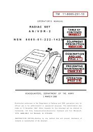
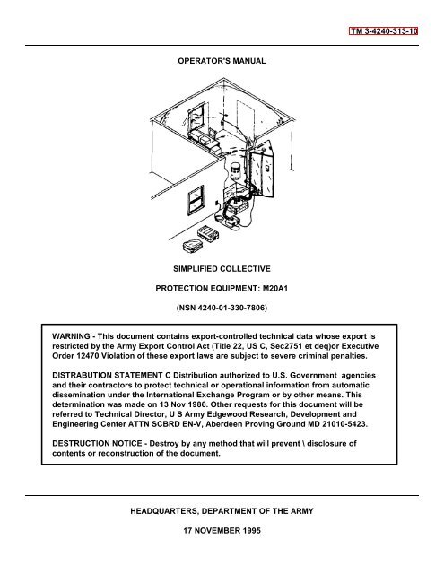
<strong>TM</strong> 3-<strong>4240</strong>-<strong>313</strong>-<strong>10</strong><br />
<strong>OPERATOR'S</strong> <strong>MANUAL</strong><br />
<strong>SIMPLIFIED</strong> COLLECTIVE<br />
PROTECTION EQUIPMENT: M20A1<br />
(NSN <strong>4240</strong>-01-330-7806)<br />
WARNING - This document contains export-controlled technical data whose export is<br />
restricted by the Army Export Control Act (Title 22, US C, Sec2751 et deq)or Executive<br />
Order 12470 Violation of these export laws are subject to severe criminal penalties.<br />
DISTRABUTION STATEMENT C Distribution authorized to U.S. Government agencies<br />
and their contractors to protect technical or operational information from automatic<br />
dissemination under the International Exchange Program or by other means. This<br />
determination was made on 13 Nov 1986. Other requests for this document will be<br />
referred to Technical Director, U S Army Edgewood Research, Development and<br />
Engineering Center ATTN SCBRD EN-V, Aberdeen Proving Ground MD 2<strong>10</strong><strong>10</strong>-5423.<br />
DESTRUCTION NOTICE - Destroy by any method that will prevent \ disclosure of<br />
contents or reconstruction of the document.<br />
HEADQUARTERS, DEPAR<strong>TM</strong>ENT OF THE ARMY<br />
17 NOVEMBER 1995
<strong>TM</strong> 3-<strong>4240</strong>-<strong>313</strong>-<strong>10</strong><br />
WARNING<br />
TOXIC HAZARD<br />
Decontaminate all contaminated equipment and personnel before erecting Simplified Collective<br />
Protection Equipment (SCPE).<br />
When erecting SCPE in a toxic environment, protective mask and clothing must be worn by all<br />
personnel until SCPE is deployed and operational. The level of protective clothing will be<br />
determined by the unit commander.<br />
When SCPE is deployed in a toxic environment, it may take up to 1-1/2 hours from time blower is<br />
turned on to purge liner of toxic vapors. Personnel who must enter SCPE during 1-1/2 hour<br />
purge time shall wear clean, uncontaminated protective clothing. Failure to do so could result in<br />
prolonged purge time and recontamination of personnel.<br />
Do not locate blower near an area where exhaust gasses are generated because filter will not<br />
remove carbon monoxide.<br />
NOISE HAZARD<br />
The blower operating noise may be hazardous to operator hearing. Hearing protection must be<br />
worn when remaining within 4 feet of blower in operation.<br />
INJURY HAZARD<br />
Three major components of SCPE weigh approximately <strong>10</strong>0 pounds each. Lifting and/or carrying<br />
can be accomplished by no fewer than two personnel.<br />
Improper lifting of PE top when erecting may cause back strain to personnel. To avoid back<br />
strain follow, proper lifting procedures.<br />
Sharp edges of the filter canister can cause injury to personnel. Use care when connecting or<br />
disconnecting air ducts to filter.<br />
Keep hands clear of leg hinges when erecting or striking protective entrance (PE).<br />
FIRE HAZARD<br />
Keep flame, spark and heat clear of SCPE.<br />
HIGH VOLTAGE<br />
High voltage exists in motor blower and recirculation filter. To prevent electrical shock ensure<br />
motor blower power switch is in off (down) position before connecting or disconnecting power<br />
cable.<br />
Disconnect power cable before performing any maintenance procedures.<br />
FIRST AID<br />
For first aid information, refer to FM 21-11.<br />
a/(b blank)
<strong>TM</strong> 3-<strong>4240</strong>-<strong>313</strong>-<strong>10</strong><br />
Technical Manual<br />
No. 3<strong>4240</strong>-413-<strong>10</strong><br />
<strong>OPERATOR'S</strong> <strong>MANUAL</strong><br />
FOR<br />
HEADQUARTERS<br />
Department of the Army<br />
Washington, D.C., 17 November 1995<br />
<strong>SIMPLIFIED</strong> COLLECTIVE PROTECTION EQUIPMENT: M20A1<br />
(NSN <strong>4240</strong>-01-330-7806)<br />
REPORTING ERRORS AND RECOMMENDING IMPROVEMENTS<br />
You can help improve this manual. If you find any mistake or if you know of a way to<br />
improve the procedures, please let us know. Mail your letter or DA Form 2028<br />
(Recommended Changes to Publications and Blank Form) direct to: Technical Director,<br />
U.S. Army Edgewood Research, Development and Engineering Center, ATTN: SCBRD-<br />
ENL-V, Aberdeen Proving Ground, MD 2<strong>10</strong><strong>10</strong>-5423. A reply will be furnished to you.<br />
WARNING<br />
This document contains export-controlled technical data whose export is restricted by the Army<br />
Export Control Ac (Title 22, U.S.C., Sec 2751 et seq) or Executive Order 12470. Violation of these<br />
export laws are subject to severe criminal penalties.<br />
DISTRIBUTION STATEMENT C: Distribution authorized to U.S. Government agencies and their<br />
contractors to protect technical or operational information from automatic dissemination under<br />
the International Exchange Program or by other means. This determination was made on 13 Nov<br />
86. Other requests for this document will be referred to: Technical Director, U.S. Army<br />
Edgewood Research, Development and Engineering Center, ATTN: SCBRD-ENL-V, Aberdeen<br />
Proving Ground, MD 2<strong>10</strong><strong>10</strong>-5423.<br />
DESTRUCTION NOTICE Destroy by any method that will prevent disclosure of contents or<br />
reconstruction of the document.<br />
TABLE OF CONTENTS<br />
HOW TO USE THIS <strong>MANUAL</strong> ............................................................................................<br />
Page<br />
iv<br />
CHAPTER 1 INTRODUCTION ................................................................................................................ 1-1<br />
Section I General Information ............................................................................................................ 1-1<br />
Section II Equipment Description and Data ......................................................................................... 1-3<br />
Section III Principles of Operation .................................................................................................. 1-<strong>10</strong><br />
i
<strong>TM</strong> 3-<strong>4240</strong>-<strong>313</strong>-<strong>10</strong><br />
TABLE OF CONTENTS (CONT)<br />
Page<br />
CHAPTER 2 OPERATING INSTRUCTIONS ........................................................................................... 2-1<br />
Section I Description and Use of Operators Controls and Indicators ................................................... 2-2<br />
Section II Preventive Maintenance Checks and Services (PMCS) ...................................................... 2-5<br />
Section III Operation Under Usual Conditions ...................................................................................... 2-22<br />
Section IV Operation Under Unusual Conditions .................................................................................. 2-63<br />
CHAPTER 3 MAINTENANCE INSTRUCTIONS ...................................................................................... 3-1<br />
Section I Lubrication Instructions ....................................................................................................... 3-1<br />
Section II Troubleshooting Procedures ................................................................................................ 3-1<br />
Section III Maintenance Procedures .............................................................................................. 3-5<br />
APPENDIX A REFERENCES ................................................................................................................... A-1<br />
APPENDIX B COMPONENTS OF END ITEM AND BASIC ISSUE ITEMS UST ....................................... B-1<br />
APPENDIX C ADDITIONAL AUTHORIZATION UST (AAL) ............................................................................... C-1<br />
APPENDIX D EXPENDABLE AND DURABLE ITEMS LIST............................................................................... D-1<br />
ALPHABETICAL INDEX .....................................................................................................Index-1<br />
ii/(iii blank)
<strong>TM</strong> 3-<strong>4240</strong>-<strong>313</strong>-<strong>10</strong><br />
M20A1 Simplified Collective Protection Equipment<br />
1-0
<strong>TM</strong> 3-<strong>4240</strong>-<strong>313</strong>-<strong>10</strong><br />
CHAPTER 1<br />
INTRODUCTION<br />
Section I. GENERAL INFORMATION<br />
1-1. SCOPE.<br />
a. Type of Manual. This is the operator's manual for use with the M20A1 Simplified Collective Protection<br />
Equipment (SCPE).<br />
b. Equipment Name and Model Number. Simplified Collective Protection Equipment: M20Al<br />
c. Purpose of Equipment. The SCPE provides a clean-air shelter for use against chemical and biological warfare<br />
agents and radioactive particles. The SCPE is an inflatable shelter which allows personnel to perform duties without<br />
wearing individual protective equipment.<br />
d. Special Limitations. The M20A1 SCPE should be deployed in a structurally sound building. It MUST NOT be<br />
deployed outside, where it would be subject to wind, rain, solar heat loading, or direct contact with liquid agents. The<br />
SCPE does not provide:<br />
(1) Environmental control equipment (heating and cooling); however, interfaces are provided.<br />
(2) A portable source of electrical power (electrical generator).<br />
(3) NBC detection devices.<br />
(4) Protection from nuclear radiation, however, the SCPE does provide protection against radioactive<br />
particles.<br />
(5) Protection from carbon monoxide exhaust gasses.<br />
1-2. MAINTENANCE FORMS AND RECORDS.<br />
Department of the Army forms and procedures used for equipment maintenance will be those prescribed by DA<br />
PAM 738-750, The Army Maintenance Management System (TAMMS).<br />
1-3. DESTRUCTION OF ARMY MATERIEL TO PREVENT ENEMY USE.<br />
For SCPE destruction procedures to prevent enemy use, refer to <strong>TM</strong> 43)0002-31 Destruction of Chemical<br />
Weapons and Defense Equipment to Prevent Enemy Use.<br />
1-4. REPORTING EQUIPMENT IMPROVEMENT RECOMMENDATION (EIR).<br />
If your SCPE needs improvement, let us know. Send us an EIR You, the user, are the only one who can tell us<br />
what you don't like about your equipment. Let us know why you don't like the design or performance. Put it on a<br />
Standard Form 368, Quality Deficiency Report. Mail it to us at Armament and Chemical Acquisition and Logistics<br />
Activity, ATTN: AMSTA-AR-QAW-A, Rock Island, IL 61299-6000. We will send you a reply.<br />
1-1
<strong>TM</strong> 3-<strong>4240</strong>-<strong>313</strong>-<strong>10</strong><br />
1-5. CORROSION PREVENTION AND CONTROL (CPC).<br />
a. Corrosion Prevention and Control (CPC) of Army material is a continuing concern. It is important that any<br />
corrosion problems with this item be reported so that the problem can be corrected and improvements can be made to<br />
prevent the problem in future items.<br />
b. While corrosion is typically associated with rusting of metals, it can also include deterioration of other materials<br />
such as rubber and plastic. Unusual cracking, softening, swelling, or breaking of these materials may be a corrosion<br />
problem.<br />
c. If a corrosion problem is identified, it can be reported using Standard Form 368. Use of key words such as<br />
"corrosion," "rust," "deterioration," or "cracking" will assure that the information is identified as a CPC problem.<br />
d. The Standard Form 368 should be submitted to:<br />
Director<br />
U.S. Army Armament and Chemical Acquisition and Logistics Activity<br />
ATTN: AMSTA-AR-QAW-A/ Customer Feedback Center<br />
Rock Island, Illinois 61299-6000<br />
1-6. NOMENCLATURE CROSS-REFERENCE LIST.<br />
Common Name<br />
Gage<br />
M20Al SCPE<br />
Official Nomenclature<br />
Differential Pressure Gage<br />
Simplified Collective Protection Equipment: M20Al<br />
1-7. LIST OF ABBREVIATIONS.<br />
A<br />
BTU<br />
cfm<br />
cm<br />
DOT<br />
ECU<br />
HSFC<br />
Hz<br />
iwg<br />
kg<br />
kw<br />
m<br />
NA<br />
NBC<br />
PE<br />
VAC<br />
VDC<br />
Ampere<br />
British Thermal Unit<br />
Cubic feet per minute<br />
Centimeter<br />
Department of Transportation<br />
Environmental Control Unit<br />
Hermetically Sealed Filter Canister<br />
Hertz<br />
Inches of water gage<br />
Kilogram<br />
Kilowatt<br />
Meter<br />
Not Applicable<br />
Nuclear, Biological, Chemical<br />
Pressurized Protective Entrance<br />
Volt Alternating Current<br />
Volt Directing Current<br />
1-2
<strong>TM</strong> 3-<strong>4240</strong>-<strong>313</strong>-<strong>10</strong><br />
Section II. EQUIPMENT DESCRIPTION<br />
1-8 EQUIPMENT CHARACTERISTICS, CAPABIUTIES, AND FEATURES.<br />
a Characteristics.<br />
(1) Transported by truck.<br />
(2) Operates from 1<strong>10</strong>/220 VAC, 50/60 Hz power.<br />
(3) Easily maintained.<br />
(4) System can be deployed using two people.<br />
b. Capabilities and Features.<br />
(1) Includes liquid agent resistant liner.<br />
(2) Provides a recirculation filter which filters and cleans air inside the shelter.<br />
(3) Has a PE that allows personnel to move from a contaminated area into the protective shelter without<br />
introducing contaminants.<br />
(4) Can be operated without HSFC when system is used for training.<br />
(5) Accessory package contains material and repair tape for restoring damaged liners, hoses, and PE to<br />
usable condition.<br />
(6) Provides adapters to interface with environmental control unit (ECU). Two types of MIL-A-52767 ECU<br />
can be interfaced:<br />
Type 1, Size C, 18,000 BTU compact vertical air conditioner or<br />
Type 2, Size C, 18,000 BTU compact horizontal air conditioner.<br />
(7) On-board spare gaskets to repair air duct hose adapter and filter adapter are stored in the accessory<br />
package.<br />
1-3
<strong>TM</strong> 3-<strong>4240</strong>-<strong>313</strong>-<strong>10</strong><br />
1-9. LOCATION AND DESCRIPTION OF MAJOR COMPONENTS.<br />
The M20A1 SCPE has five major components:<br />
• Room Liners<br />
• PE<br />
• HSFC<br />
• Recirculation filter<br />
• Accessory package with motor blower.<br />
a Room Liners The room liner (1) is sealed in a protective plastic bag and packed in rubber-coated-fabric liner<br />
carrier bag. Liners are made from plastic film that is resistant to toxic liquids and gasses. When a PE is attached and<br />
liner is pressurized, it provides a protective area for personnel. Room liners (1) of two or more complete systems can be<br />
attached to one another with a room adapter (2) (included in liner package) to increase protective area. Exterior loops<br />
and ties (3) on the top of the liner can be used to provide unpressurized support for the room liner (1). Each M20A1<br />
SCPE is issued with three complete room liner packages (two are on-board spares).<br />
1-4
<strong>TM</strong> 3-<strong>4240</strong>-<strong>313</strong>-<strong>10</strong><br />
b. Protective Entrance (PE). Consists of a collapsible aluminum support frame (1) and a butyl coated fabric<br />
(2) enclosure. When erected, the PE is free standing. It is triangular in shape with fabric doors (3) on each side. Each<br />
door has a window (4), slit entrance with hook-and-pile fasteners (5), and hook-and-pile operated vents (6). One side has<br />
a flange (7) that is used to connect the PE to the room liner. The flange comes with two air duct sleeves (8). The outer<br />
edge of the flange has a mating hook-and-pile fastener (9). The PE also comes with interval timer (<strong>10</strong>), two gages (11),<br />
dome light (12), and power supply (13). Two carrying handles (14) are located on the top. One cable sleeve (I5) is<br />
located on the inside door.<br />
1-5
<strong>TM</strong> 3-<strong>4240</strong>-<strong>313</strong>-<strong>10</strong><br />
1-9. LOCATION AND DESCRIPTION OF MAJOR COMPONENTS (CONT).<br />
c. Hermetically Sealed Filter Canister (HSFC). Contains gas and particulate filters which remove chemical and<br />
biological agents and radioactive particles. The HSFC is connected to the motor blower by the short air duct and to the<br />
SCPE liner through the PE by the long air duct (not shown). The HSFC (1) is hermetically sealed until pull-tabs (2) are<br />
removed. The HSFC remains in its shipping crate (3) for normal use.<br />
d. Recirculation Filter. The recirculation filter is a portable self-contained unit. It is used to filter any residual NBC<br />
contaminants inside a deployed SCPE liner. The cover (1) is attached to the case (2) by four link-lock fasteners (3). The<br />
case (2) houses the blower and the power switch (4). The power cord (5) plugs into the PE power supply and provides<br />
1<strong>10</strong> VAC, 50/60 Hz to the blower. Air enters through the air inlets (6) and is forced downward through the replaceable<br />
filter element (7). Air exits through the air outlets (8).<br />
1-6
<strong>TM</strong> 3-<strong>4240</strong>-<strong>313</strong>-<strong>10</strong><br />
e. Accessory Package. The accessory package contains all materials required to initiate and sustain operation of<br />
SCPE. The accessory package is compact and man-portable. It is designed to support the SCPE and contains the<br />
following:<br />
(1) Repair Material. Used for extensive repairs of SCPE liners.<br />
(2) Motor Blower. Provides air flow to inflate and continually purge liners and PE of contaminants. Provides<br />
power for extension light, recirculation filter, and PE dome light through the power supply located in the<br />
PE.<br />
(3) Short Air Duct (5 ft long). Provides airflow from blower to HSFC, has adapters in both ends.<br />
(4) Tape. Used to repair damaged liner, liner carrier bag, air duct hoses, and PE fabric.<br />
(5) 220 VAC Cable Adapter. Provides capability to use power cable in 220 VAC (European type) power<br />
receptacles or with a generator.<br />
(6) 1<strong>10</strong> VAC Cable Adapter. Provides capability to use power cable in 1<strong>10</strong> VAC power receptacles or with a<br />
generator.<br />
(7) Extension Light. Provides interior light to liner.<br />
(8) AC Power Cable Assembly. Provides electrical link between motor blower and 1<strong>10</strong>/220 VAC cable<br />
adapters.<br />
(9) Accessory Case. Durable storage and carrying case for SCPE supplies and accessories.<br />
(<strong>10</strong>) Long Air Duct (7 ft long). Provides airflow from HSFC through PE to sealed liner.<br />
(11) Gaskets. On board spares used to repair air duct hose adapter and filter adapter. Consists of six filter<br />
adapter gaskets and three air duct hose adapter gaskets.<br />
1-7
<strong>TM</strong> 3-<strong>4240</strong>-<strong>313</strong>-<strong>10</strong><br />
1-9. LOCATION AND DESCRIPTION OF MAJOR COMPONENTS (CONT).<br />
f. ECU Adapters (AAL, App C). There are two types of ECU adapters; one for 18,000 BTU horizontal air<br />
conditioner (1) and one for 18,000 BTU vertical air conditioner (2). ECU adapters are packed in a carrier bag.<br />
1-<strong>10</strong>. DIFFERENCES BETWEEN MODELS.<br />
There is only one version of the M20A1 SCPE.<br />
1-8
<strong>TM</strong> 3-<strong>4240</strong>-<strong>313</strong>-<strong>10</strong><br />
1-11. EQUIPMENT DATA.<br />
a Dimensions and Weights of SCPE Components<br />
COMPONENT<br />
LENGTH WIDTH HEIGHT WEIGHT<br />
INCH CM INCH CM INCH CM LB KG<br />
PE (Packaged) 48 121.92 41 <strong>10</strong>4.14 9 22.86 74 33.3<br />
Accessory Package 39 99.06 24 60.96 13 33.02 76 34.2<br />
Room Liner Package 30 76.20 24 60.96 12 33.02 37 16.65<br />
HSFC (Crated) 28 71.12 30 76.20 17 43.18 120 54.43<br />
Recirculation Filter 17 43.18 17 43.18 27 68.58 40 18.0<br />
(Packaged)<br />
ECU Adapter 31 78.74 21 53.34 1 2.54 <strong>10</strong> 4.5<br />
Package<br />
(AAL, App C)<br />
b. Operating Power Requirements and Characteristics of SCPE.<br />
POWER INPUT AIRFLOW<br />
COMPONENT REQUIREMENTS VOLTAGE (CFM)<br />
Motor Blower 1654 WATTS 1<strong>10</strong> or 220 VAC 50/60 Hz 200<br />
Extension Light <strong>10</strong>0 WATTS 1<strong>10</strong> VAC NA<br />
Dome Light 14 WATTS 1<strong>10</strong> VAC NA<br />
(28 VDC)<br />
Recirculation Filter 300 WATTS 1<strong>10</strong> VAC NA<br />
1-9
<strong>TM</strong> 3-<strong>4240</strong>-<strong>313</strong>-<strong>10</strong><br />
Section III. PRINCIPLES OF OPERATION<br />
1-12. SYSTEM DESCRIPTION.<br />
a. To provide NBC protection, a higher pressure must exist inside the shelter than outside the shelter. The airflow<br />
that causes the pressure must pass through the HSFC. Small leaks in the shelter liner will have no effect as long as<br />
pressure is maintained inside shelter.<br />
b. When the system is pressurized, almost all airflow into shelter will flow through PE to the contaminated exterior.<br />
c. The blower inflates the shelter to a pressure of 0.6 iwg. Vents between shelter and PE are adjusted for pressure<br />
of 0.6 iwg in shelter, and vents between PE and outside are adjusted for pressure of 0.25 iwg in PE. Clean air flowing<br />
from shelter to outside through PE purges toxic vapors from PE.<br />
1-13. FUNCTIONAL DESCRIPTION OF MAJOR COMPONENTS.<br />
a. Motor Blower. The blower provides a minimum of 200 cubic feet of air per minute to the protective shelter<br />
through the HSFC. It will operate on 1<strong>10</strong>/220 VAC 50/60 Hz. Blower assembly provides electrical power for extension<br />
light and PE dome light through output connector J2 to the PE power supply.<br />
b. Hermetically Sealed Filter Canister (!SFC). This filter removes toxic chemical agents, biological agents, and<br />
radioactive particles from air passing through it.<br />
c. Air Ducts. The air ducts provide airflow path for air from blower through HSFC into shelter.<br />
d. Recirculation Filter. The recirculation filter removes residual toxic agents which may be present inside the<br />
SCPE liners. The recirculation filter blower motor operates from any 115 VAC 50/60 Hz electrical source.<br />
e. Room Liner. Room liners are cylindrical in shape and are inflated with filtered air from HSFC and blower.<br />
The inflated room liners provide a place to work or rest without having to wear protective clothing.<br />
f. Protective Entrance (PE). PE allows personnel to move from contaminated area into liner without introducing<br />
contaminants into protected area.<br />
g. Differential Pressure Gages. There are two gages that read from 0 iwg to 2.0 iwg. One is mounted on liner<br />
side of PE and measures difference in pressure between inside liner and outside. Another is mounted to inside wall of<br />
PE and measures difference in pressure between inside PE and outside. The gages are used when adjusting internal<br />
pressures in shelter and PE. An adjusting tool is provided to adjust gages before operation.<br />
h. Vents Two vents near the bottom of the two outer PE walls are used to adjust PE pressure. Two vents near the<br />
top of the liner side of PE wall are used to adjust shelter pressure. PE and shelter pressure can be regulated by adjusting<br />
these vents.<br />
i. Dome Light. There is one dome light mounted to the ceiling of the PE which operates at 28 VAC supplied by<br />
PE power supply.<br />
j. Interval Timer. A mechanical five-minute bell timer is mounted on the wall of the PE. It is used to time the<br />
purge period of personnel entering the SCPE from contaminated areas.<br />
1-<strong>10</strong>
<strong>TM</strong> 3-<strong>4240</strong>-<strong>313</strong>-<strong>10</strong><br />
CHAPTER 2<br />
OPERATING INSTRUCTIONS<br />
Section I Description and Use of Operator's Controls and Indicators .................................................... 2-2<br />
2-1 Motor Blower Assembly ......................................................................................................... 2-2<br />
2-2 Protective Entrance ............................................................................................................... 2-3<br />
2-3 Recirculation Filter ................................................................................................................ 2-4<br />
Section II Preventive Maintenance Checks and Services (PMCS) ......................................................... 2-5<br />
2-4 Introduction to PMCS Procedures ......................................................................................... 2-5<br />
2-5 Operator Preventive Maintenance Checks and Services for M20A1 SCPE<br />
Before ............................................................................................................................... 2-6<br />
During ............................................................................................................................... 2-15<br />
After 2-19<br />
Section III Operation Under Usual Conditions ........................................................................................ 2-22<br />
2-6 Initial Condition M20A1 SCPE ............................................................................................... 2-22<br />
2-7 Initial Adjustments and Daily Checks ..................................................................................... 2-22<br />
2-8 M20A1 SCPE Preparation and Assembly for Use .................................................................. 2-22<br />
2-9 Operating Procedures ........................................................................................................... 2-44<br />
2-<strong>10</strong> Operation of Auxiliary Equipment .......................................................................................... 2-45<br />
2-11 Preparation for Movement of M20A1 SCPE .......................................................................... 2-45<br />
2-12 Operating Instructions on Decals and Plates ......................................................................... 261<br />
Section IV Operation Under Unusual Conditions .................................................................................... 263<br />
2-13 Joining Two or More M20A1 SCPE Units .............................................................................. 2-63<br />
2-14 M20A1 SCPE Used in Area with High Ceilings ...................................................................... 264<br />
2-15 Installing M20AI Liners Without Pressurization ...................................................................... 2-66<br />
2-16 Deploying M20AI SCPE in an NBC Environment .................................................................. 2-67<br />
2-1
Section I. DESCRIPTION AND USE OF <strong>OPERATOR'S</strong> CONTROLS AND INDICATORS<br />
<strong>TM</strong> 3-<strong>4240</strong>-<strong>313</strong>-<strong>10</strong><br />
2-1. MOTOR BLOWER ASSEMBLY<br />
Key Control or Indicator Function or Use<br />
1 Time Totalizing Meter Indicates total hours of blower operation.<br />
2 Power Switch Two position toggle switch/circuit breaker controls power to blowers,<br />
extension light, and dome light. Switch is also a 20 amp circuit<br />
breaker. To reset, turn switch down (off), then up (on).<br />
2-2
<strong>TM</strong> 3-<strong>4240</strong>-<strong>313</strong>-<strong>10</strong><br />
2-2. PROTECTIVE ENTRANCE<br />
Key Control or Indicator Function or Use<br />
1 Gages Indicates air pressure difference between outside and inside PE and<br />
inside shelter and outside.<br />
Zero adjusting tool is used to turn adjusting screw either left or right<br />
to align gage needle with zero.<br />
2 Interval Timers Mechanical timer bell which monitors purge time. Personnel must<br />
remain in PE until bell sounds.<br />
2-3
Section I. DESCRIPTION AND USE OF <strong>OPERATOR'S</strong> CONTROLS AND INDICATORS (CONT)<br />
<strong>TM</strong> 3-<strong>4240</strong>-<strong>313</strong>-<strong>10</strong><br />
243. RECIRCULATION FILTER.<br />
KEY CONTROL OR INDICATOR FUNTION<br />
1 Power Switch Two-position rocker switch controls power to internal blower motor.<br />
Press switch up (on) or down (off).<br />
2-4
<strong>TM</strong> 3-<strong>4240</strong>-<strong>313</strong>-<strong>10</strong><br />
Section II. PREVENTIVE MAINTENANCE CHECKS AND SERVICES (PMCS)<br />
2-4. INTRODUCTION TO PMCS PROCEDURES.<br />
a. General The Operator PMCS table has been provided so you can keep your equipment in good operating<br />
condition and ready for its primary mission. The PMCS table is arranged to provide procedures for checks and services<br />
to be performed before, during, and after operation of the equipment. The following paragraphs provide information on<br />
how to use the PMCS table. If your equipment does not perform as required, refer to Chapter 3 under Troubleshooting<br />
for possible problems and corrective actions to be taken. Report any malfunctions or failures on the proper DA Form<br />
2404, or refer to DA PAM 738-750.<br />
b. Warnings and Cautions Always observe the warnings and cautions appearing in your PMCS table. Warnings<br />
and cautions appear before the applicable procedures. You must observe all warnings and cautions to prevent serious<br />
injury to yourself or others and to prevent damage to your equipment.<br />
2-5. OPERATOR PREVENTIVE MAINTENANCE CHECKS AND SERVICES FOR M20A1 SCPE.<br />
The following paragraphs describe the information presented in each column of the PMCS table.<br />
a. Item Number Column. Numbers in this column are for reference. When completing DA Form 2404 (Equipment<br />
Inspection and Maintenance Worksheet), include the item number for the check/service indicating a fault. Item numbers<br />
also appear in the order that you must do checks and services for the intervals listed.<br />
b. Interval Column. This column tells you when you must do the procedure in the procedure column. BEFORE<br />
procedures must be done before you operate or use the equipment for its intended mission. DURING procedures must<br />
be done during the time you are operating or using the equipment for its intended mission. AFTER procedures must be<br />
done immediately after you have operated or used the equipment.<br />
c. Item to Check/Service Column. This column identifies the item to be checked or serviced.<br />
d. Procedure Column. This column gives the procedure you must do to check or service the item listed in the<br />
Item to Check/Service column to know if the equipment is ready or available for its intended mission or for operation.<br />
You must do the procedure at the time stated in the interval column.<br />
e. Not Fully Mission Capable If: Column. Information in this column tells you what faults will keep your<br />
equipment from being capable of performing its primary mission. If you make check and service procedures that show<br />
faults listed in this column, do not operate the equipment. Follow standard operating procedures for maintaining the<br />
equipment or reporting equipment failure.<br />
f. Other Table Entries. Be sure to observe all special information and notes that appear in your table.<br />
2-5
OPERATOR PREVENTIVE MAINTENANCE CHECKS AND SERVICES FOR M20AI SCPE<br />
<strong>TM</strong> 3-<strong>4240</strong>-<strong>313</strong>-<strong>10</strong><br />
NOTE<br />
If the equipment must be kept in continuous operation, do only those procedures that can be<br />
done without disturbing operation. Make complete checks and services when the equipment is<br />
shut down.<br />
Item Interval Item To Be Procedure Not Fully Mission<br />
No. Check/Service Capable If:<br />
1 Before Room Liners a. Inspect room liners (1) for Two of the three line cannot be<br />
punctures, tears, separated seams, repaired and can no longer<br />
worn hook-and-pile fasteners, maintain pressure<br />
and proper connections. Repair<br />
fabric if necessary (para 3-3).<br />
b. Check to ensure room adapters Adapters are missing<br />
(2) are available with room liner.<br />
c. Check room adapter for worn Hook-and-pile fasteners will not<br />
hook-and-pile fastener (for stay fastened.<br />
multiple unit liners only).<br />
2-6
<strong>TM</strong> 3-<strong>4240</strong>-<strong>313</strong>-<strong>10</strong><br />
Item Interval Item To Be Procedure Not Fully Mission<br />
No. Check/Service Capable If:<br />
2 Before PROTECTIVE a. Inspect PE fabric (1) for punc- Fabric is punctured or torn, windows<br />
ENTRANCE tures or tears, broken windows broken, vent flaps missing, seams<br />
(2), missing vent flaps (3), separated, or hook-and-pile<br />
fasteners<br />
separated seams, or worn hookwill<br />
not stay closed.<br />
and-pile fasteners (4). Repair<br />
fabric if necessary (para 3-3).<br />
b. Check for distorted, cracked, or . Frame will not erect properly.<br />
bent frame (5).<br />
c. Check for broken or missing Frame legs cannot be locked into<br />
hinge pins (6) (three per leg). place.<br />
d. Check that legs are locked and Frame legs will not lock together.<br />
knob (7) is present.<br />
e. Check for broken or missing More than two link-lock fasteners<br />
link-lock fasteners (8).<br />
are broken or missing.<br />
2-7
OPERATOR PREVENTIVE MAINTENANCE CHECKS AND SERVICES FOR M20A1 SCPE (CONT)<br />
<strong>TM</strong> 3-<strong>4240</strong>-<strong>313</strong>-<strong>10</strong><br />
Item Interval Item To Be Procedure Not Fully Mission<br />
No. Check/Service Capable If:<br />
2 Before PROTECTIVE f. Inspect power supply (9) for Cracked or split wire, insulation or<br />
ENTRANCE dents or cracks. Inspect both connector or miming connector or<br />
(CONT) power cords (<strong>10</strong>) for bare wire, missing connector pins.<br />
cracked or split insulation or<br />
connector on missing connector<br />
or missing connector pins (11).<br />
3 Before INTERVAL TIMER Check that interval timer (12) Interval timer is inoperative.<br />
operates. Turn knob (13) clockwise<br />
back to zero (five minutes).<br />
Monitor to ensure timer is<br />
functioning properly and bell<br />
rings.<br />
2-8
<strong>TM</strong> 3-<strong>4240</strong>-<strong>313</strong>-<strong>10</strong><br />
Item Interval Item To Be Procedure Not Fully Mission<br />
No. Check/Service Capable If:<br />
4 Before GAGES a. Check gages (14) (located on Glass is broken, or tubing missing<br />
or<br />
inside and outside wall of PE) for damaged.<br />
broken glass (15), and ensure that<br />
tube (16) is connected.<br />
b. Check that gages adjust to zero as Gage(s) will not adjust.<br />
follows:<br />
(1) Insert zero adjusting tool (17)<br />
in adjusting screw (18).<br />
(2) Turn adjusting tool (17) right<br />
to raise or left to lower to<br />
zero.<br />
5 Before HSFC NOTE<br />
It is vital that the HSFC for SCPE be fully serviceable. As an<br />
operator you are responsible for notifying unit maintenance for<br />
replacement in accordance with filter change criteria contained<br />
in FM 3-4.<br />
Inspect HSFC (1), especially seams HSFC is dented, seam cracked or<br />
(2), for cracks, dents, or holes. dented deeper than 1/4 inch, or has<br />
Check for water damage around holes. Tab pull damaged.<br />
the tab pull.<br />
2-9
OPERATOR PREVENTIVE MAINTENANCE CHECKS AND SERVICES FOR M20AI SCPE (CONT)<br />
<strong>TM</strong> 3-<strong>4240</strong>-<strong>313</strong>-<strong>10</strong><br />
Item Interval Item To Be Procedure Not Fully Mission<br />
No. Check/Service Capable If:<br />
7 Before ACCESSORY a. Check for missing components. Components missing.<br />
PACKAGE Each kit should have:<br />
(1) Repair material<br />
(2) Motor blower assembly<br />
(3) Short air duct<br />
(4) Tape<br />
(5) 220 VAC cable adapter<br />
(6) 1<strong>10</strong> VAC cable adapter<br />
(7) Extension light<br />
b. Check 220 VAC cable adapter Cable adapters or power cable have<br />
(5), 1<strong>10</strong> VAC cable adapter (6), bare wires, cracked or split<br />
insulation<br />
and power cable (8) for bare wires, or connectors, or bent, broken or<br />
cracked or split insulation or missing connector pins or sockets.<br />
connectors, and bent, broken, or<br />
missing connector pins or sockets.<br />
2-<strong>10</strong>
<strong>TM</strong> 3-<strong>4240</strong>-<strong>313</strong>-<strong>10</strong><br />
Item Interval Item To Be Procedure Not Fully Mission<br />
No. Check/Service Capable If:<br />
7 Before MOTOR BLOWER a. Check for cracks, broken, or Housing is cracked, broken, or<br />
distorted housing (1).<br />
distorted.<br />
b. Check air outlet flange (2) for bent Air duct cannot be connected to<br />
motor<br />
pins or missing pins (3) and miss- blower assembly.<br />
ing electronic component shield<br />
(4).<br />
c. Check electrical connectors (5) Any pins are missing or electrical<br />
for cracks, dents, bent or missing cables cannot be connected to<br />
motor<br />
pins, or missing electrical connec- blower.<br />
tor covers (6).<br />
d. Check time totalizing meter (7) to Totalizing meter indicates 500 hours<br />
see if 500 hours have passed since have elapsed since last motor<br />
last blower motor replacement. replacement.<br />
2-11
OPERATOR PREVENTIVE MAINTENANCE CHECKS AND SERVICES FOR M20A1 SCPE (CONT)<br />
<strong>TM</strong> 3-<strong>4240</strong>-<strong>313</strong>-<strong>10</strong><br />
Item Interval Item To Be Procedure Not Fully Mission<br />
No. Check/Service Capable If:<br />
8 Before AIR DUCTS a. Check air duct hoses (1) for Air duct hoses punctured, torn or<br />
punctures, tears, or protruding have protruding wires.<br />
wires at end of duct. Repair hose<br />
if necessary (para 3-3).<br />
b. Check for damaged or missing Adapter, clamp, or gaskets missing<br />
adapters (2), hose clamps (3), and ` or damaged.<br />
gaskets (4).<br />
9 Before EXTENSION a. Check light (1) for cracked or Extension light has bare wires,<br />
broken<br />
LIGHT bare wires (2), missing screw on insulation, prongs missing,<br />
connector<br />
connector (3), cracked connector cracked, or screws missing.<br />
(3), or missing or bent prongs<br />
on connector (3).<br />
b. Check that lamp (4) is operating. Lamp inoperative.<br />
2-12
<strong>TM</strong> 3-<strong>4240</strong>-<strong>313</strong>-<strong>10</strong><br />
Item Interval Item To Be Procedure Not Fully Mission<br />
No. Check/Service Capable If:<br />
<strong>10</strong> Before RECIRCULATION NOTE<br />
FILTER<br />
It is vital that recirculation filter for SCPE be fully serviceable. As<br />
an operator you are responsible for notifying unit maintenance for<br />
replacement in accordance with filter change criteria contained in<br />
FM 34.<br />
a. Check electrical cable (1) for bare Cable has bare wires or broken<br />
wires or broken connector (2) or connector.<br />
missing connector or missing<br />
connector pins (3).<br />
b. Check cover (4), lower case (5), Cover, case, or fan impeller blade<br />
fan impeller blade (6),and guard damage prevents normal operation.<br />
(9) for damage.<br />
c. Check that filter (7) is present. Filter is missing.<br />
d. Remove cover by releasing four Filter has punctures or is water<br />
link-lock fasteners (8) and pull damaged.<br />
filter up and check for punctures<br />
or water damage.<br />
2-13
<strong>TM</strong> 3-<strong>4240</strong>-<strong>313</strong>-<strong>10</strong><br />
OPERATOR PREVENTIVE MAINTENANCE CHECKS AND SERVICES FOR M20A1 SCPE (CONT)<br />
Item Interval Item To Be Procedure Not Fully Mission<br />
No. Check/Service Capable If:<br />
11 During ROOM LINERS Inspect room liners (1) and adapters Liner(s), including tape repairs, can<br />
(2) for punctures, tears, separated no longer maintain pressure or<br />
hookseams,<br />
worn book-and-pile fasteners, and-pile fasteners will not stay<br />
and proper connections. Repair fastened.<br />
fabric if necessary (para 3-3).<br />
2-14
<strong>TM</strong> 3-<strong>4240</strong>-<strong>313</strong>-<strong>10</strong><br />
Item Interval Item To Be Procedure Not Fully Mission<br />
No. Check/Service Capable If:<br />
12 During PROTECTIVE Inspect PE fabric (1) for punctures PE fabric, including tape repairs no<br />
ENTRANCE or tears, broken windows (2), missing l longer maintain pressure or hookandvent<br />
flaps (3), separated seams, or pile fasteners will not stay fastened.<br />
worn hook-and -pile fasteners (4).<br />
Repair fabric if necessary (para 3-3).<br />
13 During DOME LIGHT Check that dome light (1) is on. Dome light is inoperative and no<br />
other light source is available.<br />
14 During INTERVAL Check that interval timer (2) Interval timer is inoperative.<br />
TIMER operates. Turn knob (3) clockwise<br />
back to zero (five minutes). Monitor<br />
to ensure timer is functioning properly<br />
and bell rings.<br />
2-15
OPERATOR PREVENTIVE MAINTENANCE CHECKS AND SERVICES FOR M20A1 SCPE (CONT)<br />
<strong>TM</strong> 3-<strong>4240</strong>-<strong>313</strong>-<strong>10</strong><br />
Item Interval Item To Be Procedure Not Fully Mission<br />
No. Check/Service Capable If:<br />
15 During GAGES a. Check gages (1) (located on inside Glass is broken, tubing is missing.<br />
and outside wall of PE) for broken<br />
glass (2), and tube (3) is missing.<br />
b. Check that pressure reading in PE Pressure is below 0.2 iwg in PE or<br />
is not below 0.2 iwg.<br />
below 0.4 iwg in liner.<br />
c. Check that pressure reading in<br />
liner is not below 6.4 iwg.<br />
16 During MOTOR BLOWER a. Check for noisy operation. Operating noise level is unusual.<br />
b. Ensure time totalizing meter (1) Time totalizing meter is inoperative.<br />
is operating.<br />
2-16
<strong>TM</strong> 3-<strong>4240</strong>-<strong>313</strong>-<strong>10</strong><br />
Item Interval Item To Be Procedure Not Fully Mission<br />
No. Check/Service Capable If:<br />
17 During EXTENSION Check that lamp (1) is operating. Light inoperative.<br />
LIGHT<br />
18 During RECIRCULATION NOTE<br />
FILTER<br />
It is vital that recirculation filter for SCPE be fully serviceable. As<br />
an operator you are responsible for notifying unit maintenance for<br />
filter replacement in accordance with filter change criteria<br />
contained<br />
in FM 34.<br />
Check recirculation filter (1) for<br />
noisy operation.<br />
Operating noise level is unusual.<br />
2-17
<strong>TM</strong> 3-<strong>4240</strong>-<strong>313</strong>-<strong>10</strong><br />
OPERATOR PREVENTIVE MAINTENANCE CHECKS AND SERVICES FOR M20A1 SCPE (CONT)<br />
Item Interval Item To Be Procedure Not Fully Mission<br />
No. Check/Service Capable If:<br />
19 After ROOM LINER a. Check to ensure room adapter (2) Room adapter is missing.<br />
is available with room liner.<br />
b. Check for worn hook-and-pile Hook-and-pile fasteners will not stay<br />
fasteners.<br />
fastened.<br />
20 After PROTECTIVE Check for broken or missing link- More than two link-lock fasteners<br />
are<br />
ENTRANCE lock fasteners (1). broken or missing.<br />
2-18
<strong>TM</strong> 3-<strong>4240</strong>-<strong>313</strong>-<strong>10</strong><br />
Item Interval Item To Be Procedure Not Fully Mission<br />
No. Check/Service Capable If:<br />
21 After HSFC NOTE<br />
It is vital that the HSFC for SCPE be fully serviceable. As an<br />
operator you are responsible for notifying unit maintenance<br />
for HSFC replacement in accordance with filter change criteria<br />
contained in FM 3-4.<br />
Inspect HSFC (1), especially seams HSFC is dented, seams cracked or<br />
(2), for cracks, dents, or holes. dented deeper than 1/4 inch, or has<br />
Check for water damage.<br />
holes. HSFC water damaged.<br />
22 After ACCESSORY Check for missing components. Each Components missing.<br />
PACKAGE package should have:<br />
(1) Repair material<br />
(2) Motor blower assembly<br />
(3) Short air duct<br />
(4) Tape<br />
(5) 220 VAC cable adapter<br />
(6) 1<strong>10</strong> VAC cable adapter<br />
(7) Extension light<br />
(8) Power cable assembly<br />
2-19
<strong>TM</strong> 3-<strong>4240</strong>-<strong>313</strong>-<strong>10</strong><br />
OPERATOR PREVENTIVE MAINTENANCE CHECKS AND SERVICES FOR M20AI SCPE (CONT)<br />
Item Interval Item To Be Procedure Not Fully Mission<br />
No. Check/Service Capable If:<br />
23 After MOTOR BLOWER Check time totalizing meter (I) to see Totalizing meter indicates 550 hours<br />
if 550 hours have passed since last have elapsed since last motor<br />
replaceblower<br />
motor replacement.<br />
ment.<br />
24 After RECIRCULATION NOTE<br />
FILTER<br />
It is vital that recirculation filter for SCPE be fully serviceable.<br />
As an operator you are responsible for notifying unit maintenance<br />
for filter replacement in accordance with filter change criteria<br />
contained in FM 3-4.<br />
a. Check electrical cable (1) for bare Cable has bare wires or broken<br />
wires or broken connector (2) or connector or missing connector or<br />
missing connector or missing missing connector pins.<br />
connector pins (3).<br />
b. Check cover (4), lower case (5), Cover, case, or fan impeller blade<br />
fan impeller blades (6), and guard damage prevents normal operation.<br />
(7) for damage.<br />
2-20
<strong>TM</strong> 3-<strong>4240</strong>-<strong>313</strong>-<strong>10</strong><br />
Section III.<br />
OPERATION UNDER USUAL CONDITIONS<br />
2-6. INITIAL CONDITION M20AI SCPE.<br />
a. Site Selection. Consider the following conditions when selecting a structure to house an M20A1 SCPE.<br />
(1) Location serves tactical situations.<br />
(2) Location shielded from weapons or blast.<br />
NOTE<br />
Entire M20A SCPE must be deployed indoors.<br />
(3) Location away from low areas where chemical vapors tend to collect.<br />
b. Room Selection.<br />
(1) The M20A1 SCPE should be deployed in a room with four walls, a floor and a ceiling, all in good<br />
condition.<br />
(2) Electrical power available within 25 ft. of chosen room and have at least a 15 Amp circuit breaker.<br />
2-7. INITIAL ADJUS<strong>TM</strong>ENT AND DAILY CHECKS.<br />
Perform before PMCS (para 2-5).<br />
2-8. M20A1 SCPE PREPARATION AND ASSEMBLY FOR USE.<br />
a. Preparation.<br />
CAUTION<br />
Hot radiators, heaters, and lights in selected room may damage room liner.<br />
(1) Turn off radiator, heaters, and lights in selected room.<br />
WARNING<br />
Three major components of M20AI SCPE weigh approximately <strong>10</strong>0 pounds each. Lifting and/or<br />
carrying can be accomplished by no fewer than two personnel. Failure to do so can result in<br />
severe injury to personnel.<br />
(2) Carry components of M20Al SCPE (requires two personnel) into selected structure. Place components<br />
near door of selected room.<br />
CAUTION<br />
Debris on floor of selected room may damage room liner.<br />
2-21
<strong>TM</strong> 3-<strong>4240</strong>-<strong>313</strong>-<strong>10</strong><br />
(3) Remove furnishings and debris which will interfere with deployment of SCPE.<br />
NOTE<br />
If selected room has windows, refer to your unit Standing Operating Procedures (SOP) or your<br />
supervisor for blackout procedure before continuing.<br />
Wipe dusty surfaces with dry rag (Item<strong>10</strong>, App D) before applying tape.<br />
(4) Using tape from accessory package, seal windows, pad sharp objects and overhead lights.<br />
b. M20A1 Room Liner Installation.<br />
(1) Open room liner carrier bag (1) and remove room liner (2).<br />
(2) Carry room liner (2) into prepared room. Place room liner with loop ties facing up. Carefully unfold and<br />
spread liner on floor.<br />
2-22
<strong>TM</strong> 3-<strong>4240</strong>-<strong>313</strong>-<strong>10</strong><br />
2-8. M20AI SCPE PREPARATION AND ASSEMBLY FOR USE (CONT).<br />
(3) Position room liner so it will mate with PE through doorway. If doorway cannot be used, and room is large<br />
enough, both room liner and PE can be deployed inside prepared room.<br />
CAUTION<br />
Avoid walking near edges of room liner floor. Furniture, equipment, or personnel can puncture<br />
liner if positioned where weight is placed on outer boundary of room liner floor.<br />
NOTE<br />
Two personnel must hold top of room liner opening high to allow entry. Furniture or equipment<br />
is placed as close to center of room liner as possible.<br />
(4) Place furniture or equipment in room liner (2).<br />
(5) Remove extension light (3) from accessory package and place on floor inside room liner (2).<br />
(6) Place recirculation filter blower (1) on floor inside room liner (2) where it will not interfere with personnel<br />
movement.<br />
2-23
<strong>TM</strong> 3-<strong>4240</strong>-<strong>313</strong>-<strong>10</strong><br />
c. Installing Protective Entrance (PE).<br />
WARNING<br />
PE weighs approximately 74 lbs. At least two personnel are required to carry and erect PE to<br />
prevent injury to personnel.<br />
(1) Place PE (1) near the room liner entrance, where it will be used.<br />
(2) Unlock link-lock fasteners (2) on three sides of PE (1).<br />
(3) Ensure locking bar (3) on each PE leg (4) is in unlocked position.<br />
2-24
<strong>TM</strong> 3-<strong>4240</strong>-<strong>313</strong>-<strong>10</strong><br />
2-8. M20A1 SCPE PREPARATION AND ASSEMBLY FOR USE (CONT).<br />
WARNING<br />
Improper lifting of PE top when erecting may cause back strain to personnel. To avoid back<br />
strain, follow proper lifting procedures.<br />
(4) To avoid back strain, lift PE top as follows:<br />
NOTE<br />
Two personnel are required to lift PE.<br />
(a)<br />
Squat down with knees bent and back straight.<br />
(b) Grasp handles (5).<br />
(c) Keep back straight and use your legs to left PE top (6).<br />
WARNING<br />
Keep hands clear of leg hinges when erecting PE. Pinching hands or skin in hinged joints can<br />
cause serious injury.<br />
(5) At chest height, while holding handle (5) firmly, slip one hand to underside of PE top (6). Holding top up<br />
from below, move other hand to underside of PE top.<br />
2-25
<strong>TM</strong> 3-<strong>4240</strong>-<strong>313</strong>-<strong>10</strong><br />
(6) Push top (6) up as high as possible. While holding top (6) up with one hand, firmly grasp one PE leg (4)<br />
with other hand.<br />
(7) While firmly holding PE leg (4) with one hand, move other hand to opposite leg and pivot both legs to a<br />
straight position.<br />
(8) Push locking device (7) on each leg (4) in and down to lock.<br />
(9) Using attached zero adjusting tool (8), adjust gage (9), on outside PE wall, to zero.<br />
(<strong>10</strong>) Using attached zero adjusting tool (8), adjust gage (<strong>10</strong>), on inside PE wall, to zero.<br />
(11) Position PE next to PE airlock adapter.<br />
(12) Pass power cord (11) from inside PE through cable sleeve (12) and duct sleeve (13).<br />
(13) Tighten cable sleeve.<br />
2-26
<strong>TM</strong> 3-<strong>4240</strong>-<strong>313</strong>-<strong>10</strong><br />
2-8. M20A1 SCPE PREPARATION AND ASSEMBLY FOR USE (CONT).<br />
d. Attaching Room Liner to PE.<br />
(1) If passage from PE to room liner is through an existing doorway, position PE so flange (1) extends into<br />
doorway (2).<br />
NOTE<br />
Attaching room liner to PE requires two personnel.<br />
Mate hook-and-pile fasteners as smoothly as possible to avoid excess air leakage from room<br />
liner.<br />
(2) Lift top of room liner (3) opening over your head and step inside room liner. Aline top of room liner with<br />
top of PE flange (1).<br />
2-27
<strong>TM</strong> 3-<strong>4240</strong>-<strong>313</strong>-<strong>10</strong><br />
(3) Second person enters room liner, attaches room liner (3) to PE flange (1) by first attaching top corners,<br />
then working hook-and-pile fasteners (4) toward center. Pinch off any excess material at center.<br />
(4) Attach bottom two corners and work hook-and-pile fasteners (4) toward center. Pinch off excess material<br />
at bottom center.<br />
(5) Working from corners, join hook-and-pile fasteners (4) along the sides. Pinch off any excess material at<br />
centers.<br />
e. Assembling Motor Blower and HSFC.<br />
CAUTION<br />
Do not drop the hermetically sealed filter canister (HSFC). Dropping could cause broken seals.<br />
(1) Place crated HSFC (1) as close to PE (2) as possible and in vicinity of power source (3).<br />
2-28
<strong>TM</strong> 3-<strong>4240</strong>-<strong>313</strong>-<strong>10</strong><br />
2-8. M20A1 SCPE PREPARATION AND ASSEMBLY FOR USE (CONT).<br />
WARNING<br />
Do not locate motor blower near an area where exhaust gasses are generated because HSFC will<br />
not remove carbon monoxide. Breathing carbon monoxide gasses can cause serious illness or<br />
death to personnel inside SCPE.<br />
(2) Remove motor blower (4) from accessory package (5) and place it beside crated HSFC (1).<br />
2-29
<strong>TM</strong> 3-<strong>4240</strong>-<strong>313</strong>-<strong>10</strong><br />
(3) Remove long air duct (6) (has one adapter) from accessory package.<br />
(4) Feed end without adapter through duct sleeve (7) on PE fange (8).<br />
(5) Fasten hook-and-pile strap (9) around air duct.<br />
(6) Secure duct sleeve strap (<strong>10</strong>) around duct sleeve (7).<br />
(7) Tie off unused duct sleeve.<br />
2-30
<strong>TM</strong> 3-<strong>4240</strong>-<strong>313</strong>-<strong>10</strong><br />
2-8. M20A1 SCPE PREPARATION AND ASSEMBLY FOR USE (CONT).<br />
(8) Open lid of crate containing HSFC (1) as follows:<br />
(a)<br />
(b)<br />
Unfold wire loops (11) holding lid (12) closed and fold lid back.<br />
Remove foam cover (13) from crate. Set foam cover aside for re-use.<br />
WARNING<br />
Sharp edges on the HSFC can cause injury to personnel. Use care when connecting or<br />
disconnecting air ducts to HSFC.<br />
NOTE<br />
Odor of ammonia is common when HSFC is first opened. Odor will soon disappear and is not<br />
harmful to personnel.<br />
(9) Remove outlet (outer) port pull-tab lid (14) from HSFC (1).<br />
(<strong>10</strong>) Connect adapter end of long air duct (6) to outlet port (15) by pushing spring button (16) in.<br />
(11) Insert adapter in outlet port (15) by pushing in spring button (16).<br />
2-31
<strong>TM</strong> 3-<strong>4240</strong>-<strong>313</strong>-<strong>10</strong><br />
(12) Remove short air duct (17) from accessory package and attach to output of motor blower as follows:<br />
(a)<br />
(b)<br />
Aline slots in adapter (18) with pins in motor blower outlet port (19). Push adapter in.<br />
Rotate adapter clockwise to lock in place.<br />
(13) Remove inlet center port pull-tab lid (20) from HSFC (1).<br />
(14) Connect other end of short air duct (17) to inlet port (21) of HSFC.<br />
(15) Remove any kinks or bends in air ducts by moving components.<br />
2-32
<strong>TM</strong> 3-<strong>4240</strong>-<strong>313</strong>-<strong>10</strong><br />
2-8. M20A1 SCPE PREPARATION AND ASSEMBLY FOR USE (CONT).<br />
WARNING<br />
To prevent electrical shock, ensure motor blower power switch is in off (down) position before<br />
connecting or disconnecting power cable.<br />
(16) Remove power cable (22) from accessory package.<br />
(17) Remove connector covers (23) from motor blower (24) connectors J1 (25) and J2 (26).<br />
(18) Connect power cable (22) connector P2 to input connector Jl (25) of motor blower (24).<br />
(19) Connect power cable (22) connector P1 to either the 1<strong>10</strong> VAC cable adapter (27) or 220 VAC cable<br />
adapter (28) depending on power source available.<br />
(20) Connect PE power supply power cord (29) and connect to output connector J2 (26).<br />
(21) Connect cable adapter (27 or 28) to power source.<br />
2-33
<strong>TM</strong> 3-<strong>4240</strong>-<strong>313</strong>-<strong>10</strong><br />
f. Installing Recirculation Filter.<br />
(1) Check that recirculation filter power switch (1) is in down (off) position.<br />
(2) Place recirculation filter inside room liner where it will not interfere with personnel movement or restrict<br />
airflow.<br />
CAUTION<br />
To avoid overloading motor blower, do not plug more than one recirculation filter blower into PE<br />
power supply.<br />
(3) Plug recirculation filter power cord (2) into PE power supply.<br />
g. Inflating Room Liner.<br />
(1) Close all vents (1) on PE.<br />
2-34
<strong>TM</strong> 3-<strong>4240</strong>-<strong>313</strong>-<strong>10</strong><br />
2-8. M20A1 SCPE PREPARATION AND ASSEMBLY FOR USE (CONT).<br />
WARNING<br />
Motor blower operating noise may be hazardous to operator hearing. Hearing protection must be<br />
worn when remaining within 4 feet of motor blower in operation. Failure to wear hearing<br />
protection can result in hearing loss.<br />
NOTE<br />
Walking into and out of SCPE liner should be kept to a minimum so liner can inflate quickly.<br />
(2) Turn motor blower power switch (2) to the up (on) position.<br />
(3) As room liner begins to inflate, enter room liner (one person only). Before room liner is fully inflated,<br />
attach extension light (4) to room liner ceiling, using hook-and-pile fasteners (5). Smooth out room liner<br />
material and remove wrinkles from floor and walls. Watch room liner as it inflates, making sure that it<br />
does not snag on any objects within room.<br />
2-35
<strong>TM</strong> 3-<strong>4240</strong>-<strong>313</strong>-<strong>10</strong><br />
(4) Pass plug end of extension light cord (6) through PE cable sleeve (7).<br />
(5) Insert plug into outlet on power supply (8).<br />
(6) Secure cable sleeve (7) around extension light cord (6).<br />
NOTE<br />
To conserve filter life, do not turn on recirculating filter until room liner is inflated.<br />
(7) Turn recirculation filter power switch to the up (on) position.<br />
h. Adjusting Internal Pressures.<br />
NOTE<br />
Two personnel are required to adjust internal pressures of PE and room liner, one in PE and<br />
other in liner.<br />
Opening vents from liner to PE will reduce the pressure in liner and increase pressure in PE.<br />
Opening vents from PE to outside will reduce pressure in PE.<br />
Change only one vent at a time. Wait at least <strong>10</strong> seconds between changes to allow pressures to<br />
stabalize.<br />
Maximum allowable operating pressure in liner is 1.20 iwg; minimum allowable operating<br />
pressure in liner is 0.6 iwg.<br />
2-36
<strong>TM</strong> 3-<strong>4240</strong>-<strong>313</strong>-<strong>10</strong><br />
2-8. M20A1 SCPE PREPARATION AND ASSEMBLY FOR USE (CONT).<br />
(1) Set one interior vent (1) and one exterior vent (2) to half open (others are closed). From inside liner,<br />
monitor internal gage (3).<br />
(2) Allow liner pressure to build up to 1.20 iwg (close interior vents (1) as necessary).<br />
(3) After liner pressure has stabilized between 0.6 and 1.20 iwg, as indicated on PE internal gage (3), adjust<br />
exterior vents (2), as required to maintain the pressure between 0.2 and 0.3 iwg in PE. From inside PE,<br />
monitor external gage (4).<br />
2-37
<strong>TM</strong> 3-<strong>4240</strong>-<strong>313</strong>-<strong>10</strong><br />
i. Installing Horizontal ECU Adapter (AAL, App C).<br />
(1) Loosen four 1/4 turn fasteners (1) from ECU adapter frame (2).<br />
(2) Separate inner ECU adapter frame (2) from outer ECU adapter frame (3).<br />
(3) Using screwdriver (Item 11, App D), remove screws (4) from front of ECU duct (5) and remove ECU duct<br />
(5).<br />
(4) Place ECU adapter duct (6) around ECU duct (5).<br />
(5) Using screwdriver (item 11, App D), install ECU duct (5) on ECU (7).<br />
(6) Place ECU (7) next to room liner (8) exterior to determine the position ECU adapter will be installed on<br />
room liner.<br />
(7) From outside room liner (8), have person hold outer ECU adapter frame (3) against room liner (8) at<br />
position determined in step 6.<br />
2-38
<strong>TM</strong> 3-<strong>4240</strong>-<strong>313</strong>-<strong>10</strong><br />
2-8. M20A1 SCPE PREPARATION AND ASSEMBLY FOR USE (CONT).<br />
(8) From inside room liner (8) have another person aline inner ECU adapter frame (2) with outer frame.<br />
(9) From inside room liner (8) tighten four 1/4 turn fasteners (1) through inner ECU adapter frame (2), room<br />
liner (8), and outer ECU adapter frame (3).<br />
(<strong>10</strong>) Using pocket knife (Item 6, App D) cut room liner material (8) from inside ECU adapter frame (2).<br />
(11) Feed ECU power cord (9) through ECU adapter duct sleeve (<strong>10</strong>) and secure duct sleeve around ECU<br />
power cord (9).<br />
2-39
<strong>TM</strong> 3-<strong>4240</strong>-<strong>313</strong>-<strong>10</strong><br />
WARNING<br />
Do not operate ECU with ECU make up air ports open. System will become contaminated which<br />
can result in serious illness, injury, or death to personnel.<br />
(12) Close ECU make up air ports (11).<br />
(13) Operate ECU in accordance with <strong>TM</strong> 5-4120-379-14.<br />
j. Installing Vertical ECU Adapter.<br />
(1) Loosen four 1/4 turn fasteners (1) on both vertical ECU adapter frames (2).<br />
(2) Separate inner ECU adapter frames (3) from outer ECU adapter frames (2).<br />
2-40
<strong>TM</strong> 3-<strong>4240</strong>-<strong>313</strong>-<strong>10</strong><br />
2-8. M20A1 SCPE PREPARATION AND ASSEMBLY FOR USE (CONT).<br />
(3) Using screwdriver (Item 11, App D), loosen screws (4) from front of ECU ducts (5) and remove ECU ducts<br />
(5).<br />
(4) Place ECU adapter ducts (6) around ECU ducts (5).<br />
(5) Using screwdriver (Item 11, App D), install ECU ducts (5) on ECU (7).<br />
(6) Place ECU (7) next to room liner (8) exterior to determine the position ECU adapter will be installed to<br />
room liner.<br />
(7) From outside room liner (8) have person hold inner ECU adapter frames (3) against room liner (8) at<br />
position determined in step 6.<br />
2-41
<strong>TM</strong> 3-<strong>4240</strong>-<strong>313</strong>-<strong>10</strong><br />
(8) From inside room liner (8) have another person aline outer ECU adapter frames (2) with inner frames (3).<br />
(9) From inside room liner (8) tighten four 1/4 turn fasteners (1) on each interface frame through outer ECU<br />
adapter frames (2), room liner (8), and inner ECU adapter frames (3).<br />
(<strong>10</strong>) Using pocket knife (Item 6, App D) cut room liner material (8) from inside both ECU adapter frames (2).<br />
WARNING<br />
Do not operate ECU with ECU make up air ports open. System will become contaminated which<br />
can result in serious illness, injury, or death to personnel.<br />
(11) Close ECU make up air ports.<br />
(12) Operate ECU in accordance with <strong>TM</strong> 5-4120-379-14.<br />
2-42
<strong>TM</strong> 3-<strong>4240</strong>-<strong>313</strong>-<strong>10</strong><br />
2-9. OPERATING PROCEDURES.<br />
a. General.<br />
(1) Personnel entering SCPE shall follow entry procedures in FM 3-4 and unit SOP when chemical or<br />
biological contamination of protective clothing or personal equipment is known or suspected.<br />
(2) When SCPE is deployed in a toxic environment, it may take up to 1-1/2 hours to purge liner of toxic vapors<br />
from time motor blower is turned on.<br />
(3) Make sure motor blower and recirculation filter are on and operating.<br />
b. PE Entry Procedure.<br />
WARNING<br />
Personnel who enter SCPE must wear clean, uncontaminated protective mask and clothing.<br />
Failure to wear uncontaminated protective mask and clothing can result in further contamination<br />
of personnel. Contact with biological or chemical agents can result in serious illness, injury, or<br />
death.<br />
WARNING<br />
Do not take equipment into interior of SCPE unless you are certain that it has never become<br />
contaminated or that it has been thoroughly decontaminated. This includes your weapon.<br />
NOTE<br />
Only one person may enter PE at a time.<br />
(1) Before entering PE, look through PE window to ensure PE is unoccupied.<br />
(2) Enter PE and ensure door is closed and hook-and-pile fasteners are sealed. Set interval timer, mounted<br />
on PE inside wall, by turning knob fully clockwise to 5 minutes.<br />
(3) If interval timer does not sound or knob does not return to zero, reset timer to five minutes (use a watch or<br />
count aloud if necessary).<br />
(4) After interval timer bell sounds, enter liner in accordance with procedures outlined in FM 34.<br />
2-43
<strong>TM</strong> 3-<strong>4240</strong>-<strong>313</strong>-<strong>10</strong><br />
c. PE Exit Procedures.<br />
(1) Exit protective area as follows:<br />
NOTE<br />
For guidance on exit procedures, see FM 34 and unit SOP.<br />
(a)<br />
Look through PE window to ensure PE is unoccupied and interval timer is set at zero. This shows<br />
that the PE has not been occupied and no wait is necessary before entering the PE. Otherwise, wait<br />
until the interval timer bell sounds (about five minutes) before exiting.<br />
(b) Turn interval timer knob to zero (5 minutes). This is to let anyone still inside shelter know when 5-<br />
minute purge time is over.<br />
(2) Exit PE in accordance with FM 3-4 and unit SOP.<br />
2-<strong>10</strong>. OPERATION OF AUXILIARY EQUIPMENT.<br />
WARNING<br />
Locate generator outside structure or in well ventilated area. Do not locate motor blower near an<br />
area where engine exhaust gasses are generated. Filter will not protect against carbon<br />
monoxide. Carbon monoxide poisoning can cause illness, incapacitation, or death to personnel.<br />
a. The SCPE can be operated from a portable generator (App C) when commercial electric power is not available.<br />
Refer to <strong>TM</strong> 5-6115-323-14 for operation of portable generator.<br />
b. Observe the following precautions:<br />
(1) Place portable generator outside building if possible.<br />
(2) If portable generator must be inside structure, place at maximum power cable length from blower.<br />
2-11. PREPARATION FOR MOVEMENT OF M20A1 SCPE.<br />
WARNING<br />
SCPE known to be or suspected of biological or chemical agent contamination, must be<br />
decontaminated before striking.<br />
Protective mask and clothing must be worn by personnel handling contaminated components of<br />
SCPE.<br />
2-44
<strong>TM</strong> 3-<strong>4240</strong>-<strong>313</strong>-<strong>10</strong><br />
2-11. PREPARATION FOR MOVEMENT OF M20A1 SCPE (CONT).<br />
a. Decontaminating SCPE.<br />
NOTE<br />
Procedures for disposal of contaminated liners and HSFC are in unit SOP and FM 34, NBC<br />
Protection.<br />
Decontaminate all components except liner (see FM 3-5, NBC Decontamination).<br />
b. Striking SCPE.<br />
NOTE<br />
Disassemble SCPE in sequence described in the following procedures. Stow accessory package<br />
items in marked slots.<br />
(1) Disconnect motor blower as follows:<br />
WARNING<br />
Ensure motor blower power switch is in down (off) position before connecting or disconnecting<br />
power cable.<br />
(a)<br />
(b)<br />
(c)<br />
Set power switch (1) to down (off) position.<br />
Disconnect 1<strong>10</strong>/220 VAC cable adapter (2) from power source.<br />
Disconnect power cable (3) from motor blower.<br />
(d) Disconnect cable adapter (2) from power cable (3).<br />
(e)<br />
(f)<br />
Stow power cable and cable adapter in accessory package.<br />
Disconnect electric power cord (4) from motor blower. Coil power cord and store on floor of PE.<br />
(g) Attach connector covers (5).<br />
(h)<br />
(i)<br />
Disconnect short air duct (6) from motor blower by turning counter-clockwise.<br />
Store motor blower in accessory package.<br />
2-45
<strong>TM</strong> 3-<strong>4240</strong>-<strong>313</strong>-<strong>10</strong><br />
(2) Remove and store extension light as follows:<br />
(a)<br />
(b)<br />
(c)<br />
Unplug extension light plug (1) from power supply (2) in PE.<br />
Disconnect hook-and-pile fastener on cable sleeve.<br />
Pull plug (1) of extension light (3) into liner.<br />
(d) Remove extension light (3).<br />
(e)<br />
(f)<br />
Wrap cord in a roll.<br />
Stow extension light in accessory package.<br />
(3) Remove and store air ducts as follows:<br />
NOTE<br />
When storing air ducts in accessory package, put one end of air duct in correct slot and carefully<br />
push rest of air duct in.<br />
(a) Depress spring button (1) on short air duct (2), tilt upward, and remove from HSFC (3).<br />
(b)<br />
Store short air duct (2) in accessory package.<br />
2-46
<strong>TM</strong> 3-<strong>4240</strong>-<strong>313</strong>-<strong>10</strong><br />
2-11. PREPARATION FOR MOVEMENT OF M20A1 SCPE (CONT).<br />
(c)<br />
Open hook-and-pile fasteners straps (4) to disconnect long air duct (5) from PE and pull air duct<br />
through duct sleeve to outside.<br />
(d) Depress spring button on long air duct (5), tilt upward, and remove from HSFC (3).<br />
(e)<br />
Store long air duct (5) in accessory package.<br />
(4) Crate HSFC as follows:<br />
(a) Replace foam cover (1) on top of HSFC (2).<br />
(b)<br />
(c)<br />
Close lid (3) of HSFC crate.<br />
Fold wire loops (4) to secure lid.<br />
2-47
<strong>TM</strong> 3-<strong>4240</strong>-<strong>313</strong>-<strong>10</strong><br />
(5) Inventory and close accessory package as follows:<br />
(a) Check that components are present (para 2-5).<br />
(b) Close cover (1) and secure three link-lock fasteners (2).<br />
(6) Strike Protective Entrance (PE) as follows:<br />
(a) Disconnect room liner (1) from PE flange (2).<br />
(b)<br />
Close all vents (3) on PE.<br />
2-48
<strong>TM</strong> 3-<strong>4240</strong>-<strong>313</strong>-<strong>10</strong><br />
2-11. PREPARATION FOR MOVEMENT OF M20A1 SCPE (CONT).<br />
(c) Unplug recirculation filter power cord (1) from PE power supply (2).<br />
(d) Remove recirculation filter power cord from PE through cable sleeve (3).<br />
WARNING<br />
Avoid pinching skin or protective garments in hinge joints to prevent injury or contamination.<br />
CAUTION<br />
Do not allow PE to collapse suddenly. Allowing PE to collapse could damage frame and fabric.<br />
2-49
NOTE<br />
Striking PE requires at least two personnel. PE may be moved to open area for easier handling.<br />
<strong>TM</strong> 3-<strong>4240</strong>-<strong>313</strong>-<strong>10</strong><br />
(e)<br />
Hold PE top up firmly with one hand. Push knob (4) on leg (5) in and up to unlock each leg.<br />
2-50
<strong>TM</strong> 3-<strong>4240</strong>-<strong>313</strong>-<strong>10</strong><br />
2-11. PREPARATION FOR MOVEMENT OF M20A1 SCPE (CONT).<br />
(f)<br />
(g)<br />
(h)<br />
(i)<br />
While still holding top with one hand, firmly grab one leg (6); push or pull to start folding action. Carefully<br />
switch hands and repeat for third leg.<br />
Using both hands, carefully lower PE top about halfway down.<br />
Slowly lower top as you bend one knee, letting top (7) rest on other knee. Place knee at center to balance<br />
PE top.<br />
While holding top of PE on your knee, tuck fabric (8) in beyond legs so when PE is closed, legs will not<br />
pinch fabric. Ensure handles on link-lock fasteners do not catch between halves when lowering PE.<br />
2-51
<strong>TM</strong> 3-<strong>4240</strong>-<strong>313</strong>-<strong>10</strong><br />
(j)<br />
(k)<br />
Grab handles (9) on top and slowly close PE. Ensure fabric does not interfere with closing, Check that<br />
fabric is not pinched in legs or top and bottom before continuing.<br />
Lock link-lock fasteners on all three sides of PE as follows:<br />
(1) Pivot fastener (<strong>10</strong>) up to meet mating part<br />
(2) Turn handle (11) clockwise until completely locked<br />
WARNING<br />
To avoid back strain, keep your back straight and use your leg muscles to lift the PE.<br />
NOTE<br />
Lifting and moving the PE requires two personnel.<br />
(1) To lift the PE 4 feet or higher from the ground, squat down (with knees bent and back straight), grasp a<br />
handle (15) with one hand and place the other hand under the PE. As you begin to lift, use your knee to<br />
hold some of the PE weight while moving your hand from the handle to the bottom of the PE.<br />
NOTE<br />
Make certain you have a firm grip on the PE before lifting higher.<br />
2-52
<strong>TM</strong> 3-<strong>4240</strong>-<strong>313</strong>-<strong>10</strong><br />
2-11. PREPARATION FOR MOVEMENT OF M20AI SCPE (CONT).<br />
(7) Remove recirculation filter as follows:<br />
(a) Coil recirculation filter power cord (1).<br />
(b)<br />
Remove recirculation filter (2) from room liner.<br />
(8) Horizontal ECU Adapter.<br />
(a)<br />
(b)<br />
Disconnect ECU power cord (1) from power source.<br />
Untie ECU adapter duct sleeve (2) and pull ECU power cord (1) through ECU adapter duct sleeve<br />
(2).<br />
(c) Loosen four 1/4 turn fasteners (3) and remove outer ECU adapter frame (4).<br />
(d)<br />
Move ECU away from liner.<br />
2-53<br />
2-53
<strong>TM</strong> 3-<strong>4240</strong>-<strong>313</strong>-<strong>10</strong><br />
NOTE<br />
Leave ECU adapter attached if it will be required during next mission.<br />
(e) Using screwdriver (Item 11, App D), remove ECU duct (5) from ECU (6).<br />
(f) Remove ECU adapter duct (7) from ECU duct (5).<br />
(g)<br />
Using screwdriver (Item 11, App D), install ECU duct on ECU.<br />
(h) Aline outer ECU adapter frame (4) with inner ECU adapter frame (8).<br />
(i) Tighten four 1/4 turn fasteners (3).<br />
2-54
<strong>TM</strong> 3-<strong>4240</strong>-<strong>313</strong>-<strong>10</strong><br />
2-11. PREPARATION FOR MOVEMENT OF M20A1 SCPE (CONT).<br />
(j)<br />
Place ECU interface in carrier bag (9) and close.<br />
(9) Vertical ECU adapters.<br />
(a)<br />
(b)<br />
(c)<br />
Disconnect ECU power cord (1) from power source.<br />
Loosen four 1/4 turn fasteners (2) on each outer ECU frame (3) and remove frames.<br />
Move ECU away from liner.<br />
2-55
<strong>TM</strong> 3-<strong>4240</strong>-<strong>313</strong>-<strong>10</strong><br />
NOTE<br />
Leave ECU adapter attached if it will be required during next mission.<br />
(d)<br />
Using screwdriver (Item 11, App D), loosen screws from front of ECU ducts (4) and remove ECU ducts.<br />
(e) Remove ECU adapter ducts (5) from ECU ducts (4).<br />
(f) Using screwdriver (Item 11, App D), install ECU ducts (4) to ECU (6).<br />
(g) Aline outer ECU frames (3) with inner ECU adapter frames (7).<br />
(h)<br />
Tighten four 1/4 turn fasteners (2) on each ECU adapter frame.<br />
2-56
<strong>TM</strong> 3-<strong>4240</strong>-<strong>313</strong>-<strong>10</strong><br />
2-11. PREPARATION FOR MOVEMENT OF M20A1 SCPE (CONT).<br />
(i)<br />
Place ECU adapter in carrier bag (8) and close.<br />
(<strong>10</strong>) Room Liner, M20A1 SCPE.<br />
NOTE<br />
If room liner has been contaminated, refer to your unit SOP, or NBC NCO for disposal<br />
instructions.<br />
If lumber and nails were used during unusual installation procedures, liner is not to be reused.<br />
Dispose of room liner in accordance with unit SOP.<br />
Extension light from accessory package may be used to provide lighting.<br />
Two additional personnel will be required to hold liner opening open to remove furniture and<br />
equipment.<br />
(a)<br />
Remove all equipment and furniture.<br />
NOTE<br />
Folding room liner requires two personnel.<br />
2-57
<strong>TM</strong> 3-<strong>4240</strong>-<strong>313</strong>-<strong>10</strong><br />
(b)<br />
(c)<br />
(d)<br />
Locate circular floor seam at bottom of opening.<br />
Straighten circular seam to form smooth circle.<br />
Locate top circular seam (above top liner opening).<br />
(e) Place top seam directly on top of bottom seam. Tuck liner sides inward to form a circle (1).<br />
(f) Fold a 13 in. width of only top layer toward center to expose liner opening (2).<br />
(g)<br />
With liner opening at center, fold left side of liner (top and bottom together), in 2-ft. wide folds, until folds<br />
reach center line. Force air out after each fold.<br />
2-58
<strong>TM</strong> 3-<strong>4240</strong>-<strong>313</strong>-<strong>10</strong><br />
2-11. PREPARATION FOR MOVEMENT OF M20A1 SCPE (CONT).<br />
(h)<br />
(i)<br />
(j)<br />
Repeat step (g) for right side. There should be about 3 to 6 in. gap between sides.<br />
Fold one side onto other. Force air out toward liner opening.<br />
Fold lengthwise into quarters. Force air out towards liner opening.<br />
(k)<br />
Place folded liner into liner bag and reseal.<br />
2-59
<strong>TM</strong> 3-<strong>4240</strong>-<strong>313</strong>-<strong>10</strong><br />
2-12. OPERATING INSTRUCTIONS ON DECALS AND INSTRUCTION PLATES.<br />
ERECTION OF PROTECTIVE ENTRANCE<br />
Motor Blower and HSFC<br />
1. UNLOCK LATCHES ALL 3 SIDES.<br />
2. GRASP HANDLES AND LIFT.<br />
3. FULLY EXTEND LEGS INTO POSITION.<br />
4. PUSH IN AND DOWN ON LOCKING KNOBS<br />
TO LOCK EACH LEG IN PLACE.<br />
5. ATTACH PROTECTIVE ENTRANCE TO<br />
LINER.<br />
6. SEE <strong>OPERATOR'S</strong> <strong>MANUAL</strong><br />
DECONTAMINATE PRIOR TO ENTRY.<br />
DO NOT REMOVE MASK UNTIL ENTRY PURGE IS<br />
COMPLETE.<br />
NO COMBUSTION HEATERS INSIDE PROTECTED<br />
AREA.<br />
SEE <strong>OPERATOR'S</strong> <strong>MANUAL</strong><br />
Protective Entrance<br />
2-60
<strong>TM</strong> 3-<strong>4240</strong>-<strong>313</strong>-<strong>10</strong><br />
2-12. OPERATING INSTRUCTIONS ON DECALS AND INSTRUCTION PLATES (CONT).<br />
Protective Entrance<br />
2-61
<strong>TM</strong> 3-<strong>4240</strong>-<strong>313</strong>-<strong>10</strong><br />
2-13. JOINING TWO OR MORE M20A1 SCPE UNITS.<br />
Section IV. OPERATION UNDER UNUSUAL CONDITIONS<br />
WARNING<br />
This procedure should be done only in an uncontaminated environment.<br />
NOTE<br />
If shelter of more than 200 square feet of floor space is needed, two or more complete SCPE<br />
systems can be joined using these procedures.<br />
a. Set up and inflate one complete M20A1 SCPE system (para 2-8).<br />
b. Select an unused door frame (1) on primary room liner (2). Door will be framed by pile fastener.<br />
c. Using hook-and-pile fastener, attach room adapter (3) to door frame.<br />
d. Unfold additional room liner (4) with door opening (5) facing primary room liner door frame (6).<br />
e. Place equipment and furniture in additional room liner as required.<br />
f. Attach additional room liner door opening (5) to room adapter (3) using hook-and-pile fastener.<br />
g. From inside primary room liner, use knife (Item 6, App D) to cut out door opening (7) leaving a one inch border<br />
inside hook-and-pile frame. As liner is being cut, air from primary room liner will inflate additional room liner.<br />
h. Using hook-and-pile fastener, attach room adapter corner flaps (8), located at each corner of adapter, to inside<br />
corners of primary (2) and additional room liner (4).<br />
2-62
<strong>TM</strong> 3-<strong>4240</strong>-<strong>313</strong>-<strong>10</strong><br />
2-14. M20A1 SCPE USED IN AREA WITH HIGH CEILINGS.<br />
a. General.<br />
NOTE<br />
Pressure inside SCPE must be adjusted (para 2-8h) before reaching between 0.6 1.20 iwg.<br />
If liner of SCPE is inflated in areas where ceiling height is greater than liner height, some loss of usable floor<br />
area will occur as liner tends to assume a ball shape. Where a ceiling is higher than 12 ft., or where there is a false<br />
ceiling which will not bear the upward force of liner (about 600 lbs), there are two methods for maintaining liner shape.<br />
b. Sandbagging.<br />
(1) Ensure all vents from PE to shelter are open.<br />
NOTE<br />
You will need 12 to 14 sandbags, depending on weight of each bag. When room liner pressure is<br />
0.6 iwg, you will need 600 lbs of sandbags.<br />
(2) Place sandbags (1) (Item 2, App D) inside liner.<br />
(3) Place sandbags evenly along outer edge of floor.<br />
(4) Adjust vents to proper pressures (para 2-8).<br />
2-63
<strong>TM</strong> 3-<strong>4240</strong>-<strong>313</strong>-<strong>10</strong><br />
c. Nailing.<br />
CAUTION<br />
Check pressure inside SCPE to be sure it does not exceed 1.20 iwg during and after nailing.<br />
Overpressure will pull out nails and cause the material to tear.<br />
NOTE<br />
Make sure that all vents from PE to shelter are fully opened. If liner is to be erected on a wooden<br />
floor, it can be held down by nailing strips of wood to floor through liner.<br />
(1) Place 12 strips of wood (1) (Item 8, App D), each 3 to 4 ft. long, evenly around perimeter of liner floor.<br />
(2) While inflating room liner, use hammer (Item 5, App D) to drive three or four nails (Item 9, App D) through<br />
each strip through room liner floor, and into room flooring. Be sure to nail wood strips on or near floor<br />
seam of room liner.<br />
(3) Adjust vents to proper pressure (para 2-8).<br />
2-64
<strong>TM</strong> 3-<strong>4240</strong>-<strong>313</strong>-<strong>10</strong><br />
2-15. INSTALLING M20A1 SCPE LINERS WITHOUT PRESSURIZATION.<br />
WARNING<br />
This procedure should be done only in a clean environment. Contamination of personnel by<br />
biological or chemical agents can cause serious injury, illness or, death.<br />
NOTE<br />
If room liner is going to be unpressurized for any reason while occupied, use the following steps<br />
to support the liner.<br />
a. Attach support lines (1) across center of room in a cross or "X' pattern at a height of approximately 7 to <strong>10</strong> feet.<br />
b. If only one support line (Item 7, App D) is used, run it from door opening to opposite side of room.<br />
c. Secure all support lines (1) to room walls by any means available.<br />
d. Aline room liner door (2) with room door (3).<br />
e. Attach liner, center row of ties (4), to passive support line (1) going from door opening (3) to opposite side of<br />
room.<br />
f. Attach remaining liner ties (5) to additional support lines (1).<br />
2-65
<strong>TM</strong> 3-<strong>4240</strong>-<strong>313</strong>-<strong>10</strong><br />
2-16. DEPLOYING M20A1 SCPE IN AN NBC ENVIRONMENT.<br />
WARNING<br />
Failure to comply with the following steps when installing the M20A1 SCPE in an NBC<br />
environment can result in contamination of personnel by biological or chemical agents and<br />
cause serious injury, illness, or death.<br />
CAUTION<br />
DS2 should not be used to decontaminate the liner. This may cause damage to the liner.<br />
NOTE<br />
Install the M20A1 SCPE (par 2-8) strictly adhering to the following additional steps.<br />
a. Decontaminate all contaminated personnel and equipment in accordance with FM 3-5 and unit SOP.<br />
b. Liner may be inflated without exterior ties and support lines.<br />
c. Equipment must be carried in prior to liner inflation.<br />
d. Using the M256AI kit (App D, item 4), ensure liner is completely purged of all contaminants prior to unmasking.<br />
e. Turn on recirculation filter.<br />
2-66
<strong>TM</strong> 3-<strong>4240</strong>-<strong>313</strong>-<strong>10</strong><br />
CHAPTER 3<br />
MAINTENANCE INSTRUCTIONS<br />
Section I. LUBRICATION INSTRUCTIONS<br />
3-1. LUBRICATION.<br />
The M20A1 SCPE requires no lubrication.<br />
3-2. INTRODUCTION.<br />
Section II. TROUBLESHOOTING<br />
a. The troubleshooting table lists common malfunctions which you may find during the operation of the SCPE or its<br />
components. You should perform the test/inspection and corrective action in the order listed.<br />
b. This manual cannot list all malfunctions that may occur, nor all test or inspections and corrective actions.<br />
If a malfunction is not listed or is not corrected by listed corrective actions, notify your supervisor.<br />
c. Only those corrective procedures that can be performed by operator are listed in the table.<br />
d. Use the following symptom index to locate troubleshooting procedures.<br />
SYMPTOM INDEX<br />
Malfunction Symptom<br />
Troubleshooting<br />
Procedure<br />
Page<br />
1. PRESSURE LOW IN LINER. 3-2<br />
2. PRESSURE LOW IN PE. 3-3<br />
3. BLOWER DOES NOT OPERATE. 3-4<br />
4. RECIRCULATION FILTER DOES NOT OPERATE. 3-4<br />
5. DOME LIGHT IN PE NOT WORKING. 3-4<br />
3-1
<strong>TM</strong> 3-<strong>4240</strong>-<strong>313</strong>-<strong>10</strong><br />
TROUBLESHOOTING<br />
MALFUNCTION<br />
TEST OR INSPECTION<br />
CORRECTIVE ACTION<br />
1. PRESSURE LOW IN LINER.<br />
Step 1. Check to see if blower has stopped.<br />
See malfunction 3.<br />
Step 2. Check for improper adjustment of vents on PE doors.<br />
Properly adjust vents (para 2-8h).<br />
Step 3. Check to see if tubing is securely connected to the gage and outlet port.<br />
Securely connect tubing.<br />
Step 4. Check to see if PE doors are not completely closed.<br />
Properly close PE doors.<br />
Step 5. Check for punctures or tears in PE.<br />
Seal as required to stop air leakage (para 3-3).<br />
Step 6. Check for improper hook-and-pile seal between PE and room liner.<br />
Open PE door to liner and one outer PE door to reduce pressure, then reseal<br />
hook-and-pile fasteners.<br />
Step 7. Check for improper hook-and-pile seal between liners and room adapter.<br />
Seal as required to stop air leakage.<br />
Step 8. Check for improper attachment of ECU adapter.<br />
Properly attach ECU adapter (para 2-8).<br />
Step 9. Check that all duct sleeves and cable are closed.<br />
Properly close all duct sleeves and cable sleeves (para 2-8).<br />
3-2
<strong>TM</strong> 3-<strong>4240</strong>-<strong>313</strong>-<strong>10</strong><br />
TROUBLESHOOTING (CONT)<br />
MALFUNCTION<br />
TEST OR INSPECTION<br />
CORRECTIVE ACTION<br />
Step <strong>10</strong>. Check for punctures or tears in liners (top, bottom, and sides).<br />
Seal as required to stop air leakage (para 3-3).<br />
Step 11. Check air ducts for punctures, tears, or improper connection.<br />
Restore ducts to operational condition (para 3-3). Properly connect air ducts (para 2-8).<br />
Step 12. Check air ducts and HSFC for obstructions.<br />
Remove obstructions.<br />
Step 13. Notify unit maintenance.<br />
2. PRESSURE LOW IN PE.<br />
Step 1. Check to see if blower has stopped.<br />
See malfunction 3.<br />
Step 2. Check for improper adjustment of vents on PE doors.<br />
Properly adjust vents (para 2-8).<br />
Step 3. Check to see if tubing is securely connected to the gage and outlet port.<br />
Securely connect tubing.<br />
Step 4. Check to see if PE doors are properly closed.<br />
Properly close PE doors.<br />
Step 5. Check for punctures or tears in PE.<br />
Seal to stop air leakage (para 3-3).<br />
Step 6. Check air ducts for punctures, tears, or improper connection.<br />
Restore ducts to operational condition (para 3-3). Properly connect air ducts (para 2-8).<br />
Step 7. Check air ducts and HSFC for obstructions.<br />
Remove obstructions.<br />
Step 8. Notify Unit Maintenance.<br />
3-3
<strong>TM</strong> 3-<strong>4240</strong>-<strong>313</strong>-<strong>10</strong><br />
MALFUNCTION<br />
TEST OR INSPECTION<br />
CORRECTIVE ACTION<br />
TROUBLESHOOTING (CONT)<br />
3. BLOWER DOES NOT OPERATE.<br />
Step 1. Check for disconnected input power cable.<br />
Connect input power cable.<br />
Step 2. Check to see if blower switch is in up (on) position.<br />
Cycle switch to full down (off) position then to up (on) position.<br />
Step 3. Notify Unit Maintenance.<br />
4. RECIRCULATION FILTER DOES NOT OPERATE.<br />
Step 1. Check for disconnected input power cable.<br />
Re-connect input power cable.<br />
Step 2. Check to see if recirculation filter blower power switch is in up (on) position.<br />
Switch power switch to up (on) position.<br />
Step 3. Notify Unit Maintenance.<br />
5. DOME LIGHT IN PE NOT WORKING.<br />
Step 1. Check to see if blower switch is in up (on) position.<br />
Cycle switch to full down (off) position then switch to up (on) position.<br />
Step 2. Check for disconnected or improperly connected electrical cables or cords.<br />
Properly connect electrical cables and cords (para 2-8).<br />
Step 3. Notify Unit Maintenance.<br />
3-4
<strong>TM</strong> 3-<strong>4240</strong>-<strong>313</strong>-<strong>10</strong><br />
Section III. MAINTENANCE PROCEDURES<br />
3-3. OPERATOR MAINTENANCE.<br />
Operator maintenance is limited to inspection and repair of room liner fabric components, and replacing hose<br />
adapter and filter adapter gaskets.<br />
a. Inspecting. Inspect components of the SCPE as described in PMCS (para 2-5).<br />
b. Repairing. Room liners, PE fabric, ECU adapter duct and air duct hoses can be restored to operating condition<br />
using tape from accessory package.<br />
To repair straight tears on room liner, ECU adapter duct and PE fabric.<br />
NOTE<br />
Silicone is applied to the zippers to permit easier opening and closing. The repair tape will not<br />
stick to areas covered with silicone.<br />
(1) If the area to be repaired is near the zippers use alcohol (Item 1, App D) and a wiping rag (Item <strong>10</strong>, App D)<br />
to clean surface prior to taping.<br />
(2) Cut or tear a strip of tape (Item 12, App D), stored in the accessory package, approximately 4 inches<br />
longer than damaged area.<br />
(3) Position tape over damaged area, pressing firmly in place from top to bottom.<br />
(4) Use cross strips of tape for added strength.<br />
To repair corner cuts or punctures on room liners, ECU adapter duct, and PE fabric.<br />
(1) Using pocket knife, (Item 6, App D) cut repair material, located in accessory package, large enough to<br />
cover damaged area.<br />
(2) Cut or tear a strip of tape approximately 4 inches longer than patch.<br />
(3) Position patch on damaged area and firmly press tape around the edges.<br />
3-5
<strong>TM</strong> 3-<strong>4240</strong>-<strong>313</strong>-<strong>10</strong><br />
3-3. OPERATOR MAINTENANCE (CONT).<br />
To repair damaged air ducts.<br />
(1) Cut or tear a piece of tape 4 inches longer than cut or slit.<br />
(2) Position tape on outside of duct and press firmly in place. For added strength position extra tape<br />
completely around taped area of duct.<br />
c. Replacing Gaskets. This procedure is used for the hose adapter and the filter adapter.<br />
(1) Remove old gasket (1 or 2).<br />
(2) Using knife (Item 6, App D), scrape old adhesive and gasket material from the adapter surface.<br />
(3) Peel away backing tape from new adapter gasket.<br />
(4) Position gasket on adapter (3) with adhesive side toward hose; press firmly in place.<br />
3-6
<strong>TM</strong> 3-<strong>4240</strong>-<strong>313</strong>-<strong>10</strong><br />
APPENDIX A<br />
REFERENCES<br />
A-1.<br />
SCOPE<br />
This appendix lists all technical manuals, field manuals, DA Pamphlets, forms, and bulletins in this manual.<br />
A-2.<br />
TECHNICAL <strong>MANUAL</strong>S<br />
Destruction of Chemical Weapons and Defense Equipment to Prevent Enemy Use...................... <strong>TM</strong> 43-0002-31<br />
Chemical, Toxicological and Missile Fuel Handler Protective Clothing .......................................... <strong>TM</strong> <strong>10</strong>-277<br />
Operator/Crew, Organizational, Intermediate (Field) (Direct Support and<br />
General Support) and Depot Maintenance Manual for Generator Set,<br />
Gasoline Engine Driven, Skid Mounted, Tubular Frame ................................................... <strong>TM</strong> 5-6115-323-14<br />
A-3. FIELD <strong>MANUAL</strong>S<br />
NBC Protection ...................................................................................................................... FM 3-4<br />
NBC Decontamination................................................................................................................... FM 3-5<br />
First Aid for Soldiers ..................................................................................................................... FM 21-11<br />
A-4. DA PAMPHLETS<br />
The Army Maintenance Management System (TAMMS) .. ............................................................ DA PAM 738-750<br />
Functional Users Manual for the Army Maintenance Management<br />
System-Aviation (TAMMS-A............................................................................................. DA PAM 738-751<br />
A-5. DA FORMS<br />
Recommended Changes to Equipment Technical Publications ..................................................... DA FORM 2028-2<br />
Equipment Inspection and Maintenance Worksheet ...................................................................... DA FORM 2404<br />
A-6. STANDARD FORMS<br />
Quality Deficiency Report.............................................................................................................. SF 368<br />
Report of Discrepancies ................................................................................................................ SF 364<br />
A-7. OTHER<br />
Common Table of Allowances ...................................................................................................... CTA 8-<strong>10</strong>0/<br />
CTA 50-970<br />
A-1/(A-2 blank)
<strong>TM</strong> 3-<strong>4240</strong>-<strong>313</strong>-<strong>10</strong><br />
APPENDIX B<br />
COMPONENTS OF END ITEM<br />
AND<br />
BASIC ISSUE ITEMS LIST<br />
Section I. INTRODUCTION<br />
C-1.<br />
SCOPE<br />
This appendix lists components of the end item and basic issue items for the M20AI Simplified Collective Protection<br />
Equipment (SCPE) to help you inventory the items for safe and efficient operation of the equipment.<br />
C-2.<br />
GENERAL<br />
The Components of End Item and Basic Issue Items (BII) Lists are divided into the following sections:<br />
a. Column (1), Illus Number, gives you the number of the item illustrated.<br />
b. Column (2), National Stock Number, identifies the stock number of the item to be used for requisitioning<br />
purposes.<br />
c. Column (3), Description and Usable On Code, identifies the Federal item name followed by a minimum<br />
description when needed. The last line below the description is the CAGEC (commercial and Government entity code) in<br />
parenthesis and the part number.<br />
d. Column (4), U/I (unit of issue), indicates how the item is issued for the National Stock Number shown in column<br />
two.<br />
e. Column (5), Qty Rqd, indicates the quantity required.<br />
B-1
<strong>TM</strong> 3-<strong>4240</strong>-<strong>313</strong>-<strong>10</strong><br />
Section II. COMPONENTS OF END ITEM<br />
(1) (2) (3) (4) (5)<br />
Illus National Stock Description Usable on Qty<br />
Number Number CAGEC and Part Number Code U/I Rqr<br />
1 <strong>4240</strong>-01-331-0170 Room SCPE Liner Package EA 1<br />
(81361) 5-19-11334<br />
2 <strong>4240</strong>-01-331-2938 Pressurized Protective Entrance EA 1<br />
(81361) 5-19-1<strong>10</strong>21<br />
3 N/A Accessory Package EA 1<br />
(81361) 5-19-11190<br />
4 <strong>4240</strong>-01-178-9936 Hermetically Sealed Filter Canister EA 1<br />
(81361) 5-19-6868<br />
5 <strong>4240</strong>-01-348-5257 Recirculation Filter EA 1<br />
(81361) 5-19-<strong>10</strong>878<br />
On-board Spares<br />
1 <strong>4240</strong>-01-331-0170 Room SCPE Liner Package EA 2<br />
(81361) 5-19-11334<br />
B-2
<strong>TM</strong> 3-<strong>4240</strong>-<strong>313</strong>-<strong>10</strong><br />
Section III. BASIC ISSUE ITEMS<br />
(1) (2) (3) (4) (5)<br />
Illus National Stock Description Usable on Qty<br />
Number Number CAGEC and Part Number Code U/I Rqr<br />
TECHNICAL <strong>MANUAL</strong>: EA 1<br />
Operator's Manual, Simplified Collective<br />
Protection Equipment: NBC, M20A1,<br />
<strong>TM</strong> 3<strong>4240</strong>-<strong>313</strong>-<strong>10</strong><br />
B-3/(B-4 blank)
<strong>TM</strong> 3-<strong>4240</strong>-<strong>313</strong>-<strong>10</strong><br />
APPENDIX C<br />
ADDITIONAL AUTHORIZATION LIST<br />
Section I. INTRODUCTION<br />
C-1.<br />
SCOPE<br />
This appendix lists additional items you are authorized for the support of the M20A1 NBC Simplified Collective Protection<br />
Equipment (SCPE).<br />
C-2.<br />
GENERAL<br />
This list identifies items that do not have to accompany the M20A1 NBC SCPE and do not have to be turned in with it.<br />
These items are authorized to you by CTA, MTOE, TDA, or JTA.<br />
C-3.<br />
EXPLANATION OF LISTING<br />
National stock numbers, descriptions, and quantities are provided to help you identify and request the additional items<br />
you require to support this equipment. The items are listed in alphabetical sequence by item name. If the item you<br />
require differs between serial numbers of the same model, effective serial numbers are shown in the last line of the<br />
description. If item required differs for different models of this equipment, the model is shown under the 'USABLE ON<br />
CODE" heading in the description column.<br />
Section II. ADDITIONAL AUTHORIZATION LIST<br />
(1) (2) (4) (5)<br />
National Description<br />
Stock CAGEC and Qty<br />
Number Part Number Usable on Code U/I Rqr<br />
MTOE Authorized Items<br />
<strong>4240</strong>-01-331-3253 ADAPTER, HORIZONTAL, ECU EA 1<br />
(81361) 5-19-11381-20<br />
<strong>4240</strong>-01-331-0170 ADAPTER, VERTICAL, ECU EA 1<br />
(81361) 5-19-11381-<strong>10</strong><br />
6115-01-150-4140 GENERATOR SET, DIESEL EA 1<br />
ENGINE, 3 Kw<br />
(30554) MEP-016B<br />
C-1/(C-2 blank)
<strong>TM</strong> 3-<strong>4240</strong>-<strong>313</strong>-<strong>10</strong><br />
APPENDIX D<br />
EXPENDABLE AND DURABLE ITEMS LIST<br />
D-1.<br />
SCOPE<br />
This appendix lists expendable and durable items that you will need to operate and maintain the M20A1 NBC Simplified<br />
Collective Protection Equipment (SCPE). This listing is for information only and is not authority to requisition the listed<br />
items. These items are authorized to you by CTA 50-970, Expendable/Durable Items (except medical, class V repair<br />
parts, and heraldic items), or CTA 8-<strong>10</strong>0, Army Medical Department Expendable/Durable Items.<br />
D-2.<br />
EXPLANATION OF COLUMNS<br />
a. Column 1. Item Number. This number is assigned to the entry in the listing and is referenced in the narrative<br />
instructions to identify the item (e.g. "Use pocket knife, Item 6, Appendix D").<br />
b. Column 2. Level. This column identifies the lowest level of maintenance that requires the item.<br />
c. Column 3. National Stock Number. This is the national stock number assigned to the item which you can use<br />
to requisition it.<br />
d. Column 4. Item Name, Description, Commercial and Government Entity Code (CAGEC), and Part<br />
Number. This provides the other information you need to identify the item.<br />
e. Column 5. Unit of Measure. This code shows the physical measurement or count of an item, such as gallon,<br />
dozen, gross, etc.<br />
Section II. EXPENDABLE/DURABLE ITEMS LIST<br />
(1) (2) (3) (4) (5)<br />
Item National ITEM NAME, DESCRIPTION<br />
Number Level Stock Number CAGEC AND PART NUMBER U/M<br />
1 C 65<strong>10</strong>-01-091-8200 ALCOHOL: PAD, ISOPROPYL EA<br />
swab, 1.75 in. width x 1.75 in. length<br />
(24065) MA-24-80<br />
2 C 8<strong>10</strong>5-01-142-9345 BAG, SAND: plastic, poly- EA<br />
propylene, single wall<br />
(81349) MIL-B-52472<br />
3 C 4230-01-<strong>10</strong>1-3984 DECONTAMINATING KIT: EA<br />
M258A1<br />
(81361) 5-77-2366<br />
D-1
<strong>TM</strong> 3-<strong>4240</strong>-<strong>313</strong>-<strong>10</strong><br />
Section II. EXPENDABLE/DURABLE ITEMS LIST (CONT)<br />
(1) (2) (3) (4) (5)<br />
Item National ITEM NAME, DESCRIPTION<br />
Number Level Stock Number CAGEC AND PART NUMBER U/M<br />
4 C 6665-01-133-4964 DETECTOR KIT: M256A1 EA<br />
(81361) D5-77-2240<br />
5 C 5120-00-900-61<strong>10</strong> HAMMER, HAND: E22, EA<br />
carpenters<br />
(81348) GGG-H-86<br />
6 C 51<strong>10</strong>-00-162-2205 KNIFE, POCKET EA<br />
(81349) MIL-K-818C<br />
7 C 8340-00-252-2297 LINE, TENT FT<br />
(81349) MIL-L-1709 Class A<br />
8 C 55<strong>10</strong>-00-272-9060 LUMBER, SOFTWOOD, BOARD: BF<br />
30 ft., 1 in. thick by 3 in. wide by<br />
6 ft. random length<br />
(81349) MIL-B-52472<br />
9 C 5315-00-753-3883 NAIL: 3 in. length, 5 lb. LB<br />
(81348) FF-N-<strong>10</strong>5<br />
<strong>10</strong> C 7920-00-205-1711 RAG, WIPING: 50 lb. BE<br />
(58536) A-A-531<br />
11 C 5120-00-542-3438 SCREWDRIVER, CROSS TIP EA<br />
(81348) GGG-S-121<br />
12 C 75<strong>10</strong>-01-266-0326 TAPE, PRESSURE SENSITIVE RO<br />
(86984) PPP-T-60<br />
D-2
<strong>TM</strong> 3-<strong>4240</strong>-<strong>313</strong>-<strong>10</strong><br />
INDEX<br />
Subject<br />
Page<br />
A<br />
Abbreviations ...................................................................................................................................... 1-2<br />
Accessory Package<br />
Description .................................................................................................................................. 1-7<br />
Inspection Before Operation........................................................................................................ 2-<strong>10</strong><br />
Inspection After Operation .......................................................................................................... 2-19<br />
Adapter Cables<br />
Connection.................................................................................................................................. 2-33<br />
Description .................................................................................................................................. 1-7<br />
Disconnect .................................................................................................................................. 2-45<br />
Inspection.................................................................................................................................... 2-<strong>10</strong><br />
Additional Authorization List, Appendix C............................................................................................ C-1<br />
Adjusting Internal Pressure ................................................................................................................. 2-36<br />
Air Duct<br />
Assembling with HSFC and Motor Blower ................................................................................... 2-31<br />
Disconnect .................................................................................................................................. 2-46<br />
Functional Description ................................................................................................................ 1-<strong>10</strong><br />
Inspection Before Operation ....................................................................................................... 2-12<br />
Repair ......................................................................................................................................... 3-5<br />
B<br />
Basic Issue Items ............................................................................................................................... B-3<br />
Bell Timer (see Interval Timer)<br />
Blower<br />
Controls and Indicators ............................................................................................................... 2-2<br />
Decals and Instruction Plates ...................................................................................................... 2-60<br />
Disconnect .................................................................................................................................. 2-45<br />
Functional Description ................................................................................................................ 1-<strong>10</strong><br />
HSFC, Assembling ..................................................................................................................... 2-28<br />
Inspection After Operation .......................................................................................................... 2-20<br />
Inspection Before Operation........................................................................................................ 2-11<br />
Inspection During Operation ....................................................................................................... 2-16<br />
C<br />
Characteristics, Capabilities, and Features, Equipment ...................................................................... 1-3<br />
Components of End Item .................................................................................................................... B-2<br />
Components of End Item and Basic Issue Items, Appendix B.............................................................. B-I<br />
Controls and Indicators........................................................................................................................ 2-1<br />
Corrosion Data Feedback ................................................................................................................... 1-2<br />
Index-1
Subject<br />
D<br />
<strong>TM</strong> 3-<strong>4240</strong>-<strong>313</strong>-<strong>10</strong><br />
Page<br />
Decals and Instruction Plates, Operating Instructions ......................................................................... 240<br />
Decontaminating SCPE ...................................................................................................................... 2-45<br />
Deploying SCPE in NBC Environment ............................................................................................... 2-66<br />
Destruction of Army Material to Prevent Enemy Use .......................................................................... 1-1<br />
Differences Between Models............................................................................................................... 1-8<br />
Differential Pressure Gage (see Gage)<br />
Dimensions and Weights .................................................................................................................... 1-9<br />
Disassembly of SCPE ........................................................................................................................ 245<br />
Dome Light<br />
Functional Description ................................................................................................................ 1-<strong>10</strong><br />
Inspection During Operation ....................................................................................................... 2-15<br />
E<br />
ECU Adapter<br />
Description .................................................................................................................................. 1-8<br />
Installation, Horizontal................................................................................................................. 2-38<br />
Installation, Vertical .................................................................................................................... 2-40<br />
Striking, Horizontal...................................................................................................................... 2-53<br />
Striking, Vertical.......................................................................................................................... 2-55<br />
Entry Procedures, Protective Entrance ............................................................................................... 2-43<br />
Equipment Characteristics, Capabilities, and Features ....................................................................... 1-3<br />
Equipment Data ................................................................................................................................. 1-9<br />
Equipment Improvement Recommendations, Reporting...................................................................... 1-1<br />
Exit Procedures, Protective Entrance.................................................................................................. 244<br />
Expendable/Durable Supplies and Materials List, Appendix D ............................................................ D-1<br />
Extension Light<br />
Description .................................................................................................................................. 1-7<br />
Inspection Before Operation ....................................................................................................... 2-12<br />
Inspection During Operation ....................................................................................................... 2-17<br />
Removing ................................................................................................................................... 2-46<br />
F<br />
Features, Capabilities, Characteristics, Equipment ............................................................................. 1-3<br />
Filters (see Recirculation Filter; HSFC)<br />
Folding Room Liners .......................................................................................................................... 2-58<br />
Forms and Records, Maintenance....................................................................................................... 1-1<br />
Functional Description of Major Components ..................................................................................... 1-<strong>10</strong><br />
Index-2
Subject<br />
G<br />
<strong>TM</strong> 3-<strong>4240</strong>-<strong>313</strong>-<strong>10</strong><br />
Page<br />
Gage<br />
Functional Description ................................................................................................................ 1-<strong>10</strong><br />
Inspection Before Operation ....................................................................................................... 2-9<br />
Inspection During Operation ....................................................................................................... 2-16<br />
H<br />
HSFC<br />
Crating ........................................................................................................................................ 2-47<br />
Decals and Instruction Plates ..................................................................................................... 2-60<br />
Description ................................................................................................................................. 1-6<br />
Functional Description ................................................................................................................ 1-<strong>10</strong><br />
Inspection After Operation .......................................................................................................... 2-19<br />
Inspection Before Operation ....................................................................................................... 2-9<br />
Motor Blower, Assembling .......................................................................................................... 2-31<br />
Hermetically Sealed Filter Canister (see HSFC)<br />
High Ceilings, M20A1 SCPE, Used in Areas With .............................................................................. 2-63<br />
I<br />
Inflating Room Liner ........................................................................................................................... 2-34<br />
Inflating Room Liner in NBC Environment .......................................................................................... 2-66<br />
Initial Adjustment and Daily Checks ................................................................................................... 2-21<br />
Initial Condition M20A1 SCPE ............................................................................................................ 2-21<br />
Installation, M20AI Room Liner .......................................................................................................... 2-22<br />
Installation in NBC Environment ......................................................................................................... 2-66<br />
Installing Liners Without Pressurization .............................................................................................. 2-65<br />
Internal Pressure, Adjusting ................................................................................................................ 2-36<br />
Interval Timer<br />
Functional Description ................................................................................................................ 1-<strong>10</strong><br />
Inspection Before Operation ....................................................................................................... 2-8<br />
Inspection During Operation ....................................................................................................... 2-15<br />
L<br />
Liner (see Room Liner)<br />
Location and Description of Major Components .................................................................................. 1-4<br />
Lubrication .......................................................................................................................................... 3-1<br />
INDEX-3
<strong>TM</strong> 3-<strong>4240</strong>-<strong>313</strong>-<strong>10</strong><br />
Subject<br />
Page<br />
M<br />
Maintenance Forms and Records........................................................................................................ 1-1<br />
Maintenance Procedures .................................................................................................................... 3-5<br />
Major Components<br />
Functional Description ................................................................................................................ 1-<strong>10</strong><br />
Location and Description ............................................................................................................ 1-4<br />
Malfunctions ....................................................................................................................................... 3-1<br />
Model Differences .............................................................................................................................. 1-8<br />
Motor Blower Assembly (see Blower)<br />
Movement, Preparation for ................................................................................................................. 2-44<br />
N<br />
Nailing................................................................................................................................................. 2-64<br />
NBC Environment, Deploying SCPE .................................................................................................. 2-66<br />
Nomenclature Cross-Reference ......................................................................................................... 1-2<br />
O<br />
Operating Instructions on Decals and Instruction Plates ...................................................................... 2-60<br />
Operating Power Requirements .......................................................................................................... 1-9<br />
Operating Procedures ........................................................................................................................ 2-43<br />
Operation Under Unusual Conditions ................................................................................................. 2-62<br />
Operation Under Usual Conditions ..................................................................................................... 2-21<br />
Operator Controls and Indicators ........................................................................................................ 2-2<br />
Operator Preventive Maintenance Checks and Services (see PMCS)<br />
Operator Troubleshooting Procedures ................................................................................................ 3-1<br />
P<br />
PMCS ................................................................................................................................................ 2-5<br />
PMCS<br />
After............................................................................................................................................ 2-18<br />
Before ........................................................................................................................................ 2-6<br />
During ........................................................................................................................................ 2-14<br />
Power Cables<br />
Connection.................................................................................................................................. 2-33<br />
Description .................................................................................................................................. 1-7<br />
Disconnection.............................................................................................................................. 2-45<br />
Inspection ................................................................................................................................... 2-11<br />
Power Requirements .......................................................................................................................... 1-9<br />
Preparation for Movement .................................................................................................................. 244<br />
Preparation and Assembly for Use ...................................................................................................... 2-21<br />
Pressure Gage (see Gage)<br />
INDEX-4
<strong>TM</strong> 3-<strong>4240</strong>-<strong>313</strong>-<strong>10</strong><br />
Subject<br />
P (CONT)<br />
Page<br />
Pressure, Adjusting Internal ................................................................................................................ 2-36<br />
Pressurized, Installing Without ........................................................................................................... 2-65<br />
Pressurized Protective Entrance (see Protective Entrance)<br />
Preventive Maintenance Checks and Services, Operator (see PMCS)<br />
Principles of Operation, Technical ...................................................................................................... 1-<strong>10</strong><br />
Procedures<br />
Assembly .................................................................................................................................... 2-21<br />
Maintenance................................................................................................................................ 3-5<br />
Operating .................................................................................................................................... 2-43<br />
Protective Entrance Entry ........................................................................................................... 2-43<br />
Protective Entrance Exit ............................................................................................................. 2-44<br />
Protective Entrance<br />
Controls and Indicators ............................................................................................................... 2-2<br />
Decals and Instruction Plates ..................................................................................................... 2-60<br />
Description .................................................................................................................................. 1-5<br />
Disassembling............................................................................................................................. 245<br />
Entry Procedures ........................................................................................................................ 2-43<br />
Exit Procedures .......................................................................................................................... 2-44<br />
Fabric Repair ............................................................................................................................. 3-5<br />
Functional Description ................................................................................................................ 1-<strong>10</strong><br />
Inspection Before Operation........................................................................................................ 2-7<br />
Inspection During Operation ....................................................................................................... 2-15<br />
Inspection After Operation .......................................................................................................... 2-18<br />
Installing ..................................................................................................................................... 2-24<br />
Striking........................................................................................................................................ 2-48<br />
R<br />
Recirculation Filter<br />
Controls and Indicators ............................................................................................................... 2-4<br />
Description .................................................................................................................................. 1-6<br />
Functional Description ................................................................................................................ 1-<strong>10</strong><br />
Installing...................................................................................................................................... 2-34<br />
Inspection Before Operation ....................................................................................................... 2-13<br />
Inspection During Operation ....................................................................................................... 2-17<br />
Inspection After Operation .......................................................................................................... 2-20<br />
Removal ..................................................................................................................................... 2-53<br />
Records and Forms, Maintenance ...................................................................................................... 1-1<br />
References, Appendix A ..................................................................................................................... A-1<br />
Repair Procedures ............................................................................................................................. 3-5<br />
Reporting Equipment Improvement Recommendations ...................................................................... 1-1<br />
Room Liner<br />
Description ................................................................................................................................. 1-4<br />
Folding........................................................................................................................................ 2-58<br />
Functional Description ................................................................................................................ 1-<strong>10</strong><br />
Inflating ....................................................................................................................................... 2-34<br />
INDEX-5
<strong>TM</strong> 3-<strong>4240</strong>-<strong>313</strong>-<strong>10</strong><br />
Subject<br />
Page<br />
R (CONT)<br />
Inflating in NBC Environment ..................................................................................................... 266<br />
Inspection After Operation........................................................................................................... 2-18<br />
Inspection Before Operation ....................................................................................................... 2-6<br />
Inspection During Operation ....................................................................................................... 2-14<br />
Installing...................................................................................................................................... 2-22<br />
Repair ......................................................................................................................................... 3-5<br />
Striking........................................................................................................................................ 2-57<br />
S<br />
Sandbagging....................................................................................................................................... 2-63<br />
SCPE Liners (see Room Liner) ...........................................................................................................<br />
Striking SCPE .................................................................................................................................... 2-45<br />
Support Kit (see Accessory Package)<br />
Symptom Index .................................................................................................................................. 3-1<br />
System Description ............................................................................................................................ 1-<strong>10</strong><br />
T<br />
Technical Principles of Operation........................................................................................................ 1-<strong>10</strong><br />
Timer Bell (see Interval Timer)<br />
Troubleshooting Procedures, Operator................................................................................................ 3-1<br />
V<br />
Vents<br />
Adjusting Internal Pressure ......................................................................................................... 2-36<br />
Functional Description ................................................................................................................ 1-<strong>10</strong><br />
W<br />
Weights and Dimensions .................................................................................................................... 1-9<br />
INDEX-6