4/03 RCSD - RC Soaring Digest - Rcsoaring.com
4/03 RCSD - RC Soaring Digest - Rcsoaring.com
4/03 RCSD - RC Soaring Digest - Rcsoaring.com

You also want an ePaper? Increase the reach of your titles
YUMPU automatically turns print PDFs into web optimized ePapers that Google loves.
The CJ-3309 has a flat lower surface<br />
from the leading edge radius back to<br />
the point where the reflex starts at 75%<br />
chord. Building a warp free wing on a<br />
flat surface is therefore automatic.<br />
The CJ-25 2 09 has what’s <strong>com</strong>monly<br />
called a “Phillips’ entry.” The lower<br />
surface curves upward from 25%<br />
chord forward to the leading edge<br />
radius. This reduces the camber from<br />
three percent to two and a half percent.<br />
Flight speeds appear to be slightly<br />
faster with this airfoil than when using<br />
the CJ-3309. Launch height is greater<br />
because of the lower drag, allowing<br />
higher zooms, and climbing ability in a<br />
thermal is not noticeably affected.<br />
The third section, the BW 05 02 09, has<br />
no flat portions on either the upper or<br />
lower surface, making a construction<br />
jig of some sort a necessity. We really<br />
like this airfoil because of its low drag<br />
and reduced reflex. The CG location is<br />
in exactly the same spot as the version<br />
with the CJ-25 2 09 section, but the<br />
natural oscillations in pitch which<br />
appear when flying straight ahead for<br />
long periods are slower and of lesser<br />
magnitude. The performance improvement<br />
over the CJ-25 2 09 is remarkable.<br />
Energy retention during zooms off the<br />
winch are consistently higher, cruising<br />
between thermals is noticeably faster,<br />
and the aircraft is more quiet.<br />
Despite the more convoluted construction<br />
methodology, we chose the BW 05<br />
02 09 for this aircraft.<br />
Page 6<br />
Flaps<br />
The topic of flaps on planks was a<br />
subject of our correspondence with<br />
Dave Jones, designer of the Blackbird<br />
2M. While such flaps cannot be used to<br />
improve thermal climb, they can be<br />
during winch launches to improve<br />
initial climbout and for glide path<br />
control during landing. The generalized<br />
“rules” for flaps on plank planforms<br />
are as follows: location of the<br />
leading edge of the flap at 40% of the<br />
local chord; approximately 5% of the<br />
wing area; deflection of 45 degrees<br />
should be sufficient.<br />
The flaps are 18 inches long and three<br />
inches wide. They consist of 1/16 inch<br />
balsa exterior and interior sheeting,<br />
and 1/8 square spruce diagonal ribs.<br />
The control horns are mounted on<br />
plywood triangles which fit into the<br />
corner under the servo output wheel.<br />
The flaps are lightweight and torsionally<br />
rigid. We used standard nylon<br />
pinned hinges, five per flap. Our<br />
Dremel was mounted on a router base<br />
and just enough balsa was removed for<br />
the hinge to be flush with the flap and<br />
wing sheeting exterior surfaces. We<br />
then cut 1/64 inch plywood into the<br />
shape of an aerodynamic strut and<br />
used that to cover the exposed surface<br />
of the hinge.<br />
We’re using Hitec HS-605BB servos<br />
throughout — one for each elevon, one<br />
for each flap, and one for the rudder.<br />
These servos are close to standard size,<br />
have dual ball bearings and helical<br />
gears, and can put out 77 oz. in. of<br />
torque at 0.16 sec./60 degrees on 4.8<br />
volts. The flap control system utilizes a<br />
short pushrod with ball links at each<br />
end. The servo wheel is set so that<br />
throttle trim (low speed) adjusts the<br />
closing position, and when the flap is<br />
fully deflected there is no pressure<br />
against the gear train. See Figure 2 and<br />
the flap servo photo.<br />
We settled on a Y-harness for the flap<br />
servos. This allows us to use the<br />
throttle channel for controlling flap<br />
deflection, the aileron and elevator<br />
channels for the elevons, and the<br />
rudder channel for the rudder. The<br />
flap servos were mounted in mirrored<br />
positions in the wings, so one servo<br />
had to be modified for reversed<br />
direction of rotation. Our original plan<br />
was to use a Hitec seven channel<br />
receiver and mixing options on the<br />
transmitter, a JR PCM 10. This channel<br />
utilization allows us to use our FMA<br />
M5 with additional protective foam<br />
surrounding it, and our JR Century 7<br />
transmitter should the need arise.<br />
Fuselage<br />
The Blackbird 2M per plan fuselage<br />
The elevon servo is mounted right behind<br />
the main spar. Notice the high strength<br />
clevis and pushrod. The Hitec HS-605BB<br />
servo puts out 77 oz. in. of torque, so the<br />
system has to be of more robust<br />
construction than the usual.<br />
The <strong>com</strong>plete flap and driving servo<br />
system. Each flap is 18 inches long<br />
and three inches wide. The leading<br />
edge sheeting is not yet in place. A<br />
rolled paper tube acts as a conduit for<br />
the elevon servo cable.<br />
The flap hinges are inset into the 1/16<br />
inch balsa sheeting, then covered with 1/<br />
64 inch plywood. The outside edges of<br />
the plywood were rounded with<br />
sandpaper before being glued in place.<br />
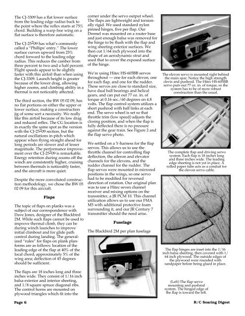
(Left) The flap servo<br />
mounting and pushrod<br />
system. The hinged edge of<br />
the flap is toward the left.<br />
R/C <strong>Soaring</strong> <strong>Digest</strong>