4/03 RCSD - RC Soaring Digest - Rcsoaring.com
4/03 RCSD - RC Soaring Digest - Rcsoaring.com
4/03 RCSD - RC Soaring Digest - Rcsoaring.com

You also want an ePaper? Increase the reach of your titles
YUMPU automatically turns print PDFs into web optimized ePapers that Google loves.
April 20<strong>03</strong><br />
View of the left front of the fuselage nose.<br />
1400 mAh battery pack, Hitec seven<br />
channel receiver, and vertically mounted<br />
rudder servo. Still plenty of room in the<br />
forward nose for lead ballast to adjust CG<br />
location.<br />
Another view of the forward fuselage<br />
showing the location of the various<br />
electronic items. The receiver location was<br />
framed for the Hitec seven channel, but the<br />
FMA M5 will be used with lots of room for<br />
protective foam.<br />
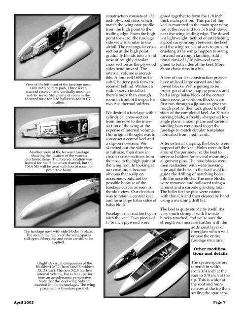
The fuselage nose with side blocks in place.<br />
The area in the region of the wing spar is<br />
still open. Fiberglass and resin are still to be<br />
applied.<br />
(Right) A visual <strong>com</strong>parison of the<br />
Blackbird XC.2 (front) and Blackbird<br />
XC.3 (rear). The new XC.3 has less<br />
internal volume, but is far superior<br />
from an aerodynamic perspective.<br />
Note that the steel wing rods are<br />
inserted into both fuselages. The wing<br />
placement is therefore parallel.<br />
construction consists of 1/8<br />
inch plywood sides which<br />
match the wing root profile<br />
from the high point to the<br />
trailing edge. From the high<br />
point forward, the fuselage<br />
side view is similar to the<br />
airfoil. The rectangular cross<br />
section at the high point<br />
gradually blends into a solid<br />
nose of roughly circular<br />
cross section as the plywood<br />
sides bend inward. The<br />
internal volume is incredible.<br />
A four cell 1600 mAh<br />
sub-C battery pack forward,<br />
receiver behind. Without a<br />
rudder servo installed,<br />
there’s more than enough<br />
room in front of the spar for<br />
two Ace thermal sniffers.<br />
We desired a fuselage with a<br />
cylindrical cross-section<br />
from the nose to the intersection<br />
of the wing at the<br />
expense of internal volume.<br />
Our original thought was to<br />
construct a central keel and<br />
a slip-on nosecone. We<br />
sketched out the side view<br />
in full size, then drew in<br />
circular cross-sections from<br />
the nose to the high point of<br />
the wing root. In looking at<br />
our creation, it became<br />
obvious that a slip on<br />
nosecone would not be<br />
possible because of the<br />
fuselage curves as seen in<br />
the side view. Our decision<br />
was to retain a central keel<br />
and form large balsa sides of<br />
balsa block.<br />
Fuselage construction began<br />
with the keel. Two pieces of<br />
1/16 inch plywood were<br />
glued together to form the 1/8 inch<br />
thick main portion. This part of the<br />
keel is mounted to the main spar wing<br />
rod at the rear and to a 5/8 inch dowel<br />
near the wing leading edge. The dowel<br />
is a lightweight method of establishing<br />
a good carrythrough between the keel<br />
and the wing roots and acts to prevent<br />
crushing if the wings happen to swing<br />
forward on a rough landing. Additional<br />
rims of 1/16 plywood were<br />
glued to both sides of the keel. More<br />
about those rims in a bit.<br />
A few of our last construction projects<br />
have utilized large carved and hollowed<br />
blocks. We’re getting to be<br />
pretty good at the shaping process and<br />
had a large balsa block of the correct<br />
dimensions to work on. Blocks were<br />
first run through a jig saw to give the<br />
rough profile, then tack glued to both<br />
sides of the <strong>com</strong>pleted keel. An X-Acto<br />
carving blade, a freshly sharpened low<br />
angle plane, a razor plane and carbide<br />
sanding bars were used to get the<br />
fuselage to match circular templates<br />
fabricated from credit cards.<br />
After external shaping, the blocks were<br />
popped off the keel. Holes were drilled<br />
around the perimeter of the keel to<br />
serve as holders for several mounting/<br />
alignment pins. The nose blocks were<br />
then reattached with wide masking<br />
tape and the holes in the keel used to<br />
guide the drilling of matching holes<br />
into the nose blocks. The nose blocks<br />
were removed and hollowed using a<br />
Dremel and a carbide grinding tool.<br />
The holes for the pins were coated<br />
with thin CA and then cleared by hand<br />
using a matching drill bit.<br />
The keel is quite sturdy by itself. It’s<br />
very much stronger with the side<br />
blocks attached, and we’re sure the<br />
strength will increase further with the<br />
additional layer of<br />
fiberglass which will<br />
encase the entire<br />
fuselage structure.<br />
Other modifications<br />
and details<br />
The spruce spars are<br />
tapered in width<br />
from 3/4 inch at the<br />
root to 3/8 inch at the<br />
tip. This is wider at<br />
the root and more<br />
narrow at the tip than<br />
scaling the spar caps<br />
Page 7