Department of Electronics - IPN - IN2P3
Department of Electronics - IPN - IN2P3
Department of Electronics - IPN - IN2P3

Create successful ePaper yourself
Turn your PDF publications into a flip-book with our unique Google optimized e-Paper software.
General & technical <strong>Department</strong>s<br />
The electtrroni<br />
ics <strong>of</strong>f ALIICE dimuon ttrracki ing chamberrs<br />
<strong>IPN</strong>O Participation : V. Chambert, P. Courtat, S. Drouet, B.-Y. Ky, J-M. Martin, C. Oziol<br />
Collaboration : Institut de Physique Nucléaire d’Orsay, Saha Institute <strong>of</strong> Nuclear Physics, Istituto<br />
Nazionale di Fisica Nucleare Sezione di Cagliari, Subatech Nantes<br />
L’électronique des chambres à fils du bras Dimuon d’Alice<br />
Le bras Dimuon de l’expérience Alice du Cern comprend entre autres un système de reconstruction de traces des<br />
particules composé de 10 chambres à fils reparties dans 5 stations. L’<strong>IPN</strong>O a en charge la coordination de<br />
l’électronique pour tout le bras Dimuon, ainsi que la construction de la station 1. Le système de lecture des<br />
chambres comprend des cartes frontales de lecture et de numérisation des données, des bus de transmission vers<br />
les châssis CROCUS de lecture et un châssis de transmission et de mise en forme du trigger. Après une brève<br />
présentation de ces systèmes nous décrirons de façon plus détaillée le système CROCUS.<br />
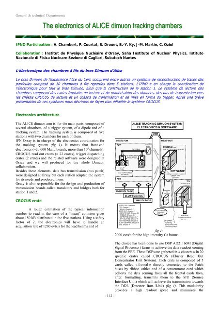
<strong>Electronics</strong> architecture<br />
The ALICE dimuon arm is, for the main parts, composed <strong>of</strong><br />
several absorbers, <strong>of</strong> a trigger system, <strong>of</strong> a dipole and <strong>of</strong> a<br />
tracking system. The tracking system is composed <strong>of</strong> five<br />
stations with two chambers for each <strong>of</strong> them.<br />
<strong>IPN</strong> Orsay is in charge <strong>of</strong> the electronics coordination for<br />
the tracking system (fig 1). It means that front-end<br />
electronics (≈20 000 Manu boards, more than 10 6 channels),<br />
CROCUS read out crates (≈ 22 crates), trigger dispatching<br />
crates (2 crates) and the related s<strong>of</strong>tware were designed at<br />
Orsay and we will produced for the whole Dimuon<br />
collaboration.<br />
Besides these elements, data bus transmission (bus patch)<br />
were designed at Orsay but each station adapted the system<br />
for its needs and produced them.<br />
Orsay is also responsible for the design and production <strong>of</strong><br />
transmission boards called translators and bridges both for<br />
station 1 and 2.<br />
CROCUS crate<br />
A rough estimation <strong>of</strong> the typical information<br />
number to read in the case <strong>of</strong> a “mean” collision gives<br />
about 150 kB distributed in the five stations. Using a safety<br />
factor <strong>of</strong> 2, the electronics will have to handle an<br />
acquisition rate <strong>of</strong> 1200 evts/s for the lead beams and <strong>of</strong><br />
DETECTOR<br />
FEE<br />
FEE<br />
2 x 32<br />
PADs<br />
PATCH BUS<br />
Up to 26 or 3 x 17<br />
MANU BOARD.<br />
Up to 100 PATCH BUS<br />
per detector.<br />
HIGH VOLTAGE<br />
MANU<br />
SLOW CONTROL<br />
DETECTOR: Chapter 1<br />
FEE: Chapter 2<br />
MANU: Chapter 2.1<br />
READ OUT: Chapter 3<br />
DISPATCHING: Chapter 3.2<br />
CROCUS: Chapter 3.3<br />
SOFTWARE: Chapter 3.4<br />
LOW VOLTAGE: Chapter 4<br />
HIGH VOLTAGE: Chapter 5<br />
SLOW CONTROL: Chapter 6<br />
EMC: Chapter 7<br />
ALICE TRACKING DIMUON SYSTEM:<br />
ELECTRONICS & SOFTWARE<br />
Translator<br />
Board.<br />
LOW VOLTAGE<br />
EMC<br />
10 Meter max<br />
Ribbon cable<br />
READ OUT.<br />
CROCUS Crate<br />
Up to 50 PATCH BUS connected.<br />
FRT<br />
DAQ<br />
Optical link:<br />
DDL<br />
100 meter.<br />
PC<br />
CRT<br />
SOFTWARE<br />
Ribbon cable<br />
40 meter<br />
TCI<br />
One crate for all<br />
CROCUS.<br />
FFT FTD<br />
Link to download:<br />
Pedestals.<br />
DSP code.<br />
From CTP<br />
Trigger information:<br />
L0, L1…..<br />
ETHERNET:<br />
- Monitoring.<br />
- Stand alone DAQ.<br />
- Test configuration.<br />
fig 1:<br />
2000 evts/s for the high intensity Ca beams.<br />
- 142 -<br />
The choice has been done to use DSP AD21160M (Digital<br />
Signal Processor) farms to achieve the data readout coming<br />
from the FEE. These DSPs are gathered in « clusters » in 20<br />
specific crates called CROCUS (Cluster Read Out<br />
Concentrator Unit System). Each crate is composed <strong>of</strong> 5<br />
cards called « frontal » directly connected to the Patch<br />
buses by ribbon cables and <strong>of</strong> a concentrator card which<br />
collects the data coming from all the frontal cards then,<br />
after, formatting, transmits them to the SIU (Source<br />
Interface Unit) which will achieve the transmission towards<br />
the DDL (Detector Data Link) (fig 1). This modularity<br />
provides a high readout speed and minimizes the