


Create successful ePaper yourself
Turn your PDF publications into a flip-book with our unique Google optimized e-Paper software.
CAUTION<br />
Rotate steering wheel to relieve hydraulic system<br />
pressure and avoid injury from pressurized<br />
hydraulic oil.<br />
11. If the mounting plate assembly is being removed<br />
from machine, label all hydraulic connections for reassembly<br />
purposes. Clean hydraulic hose ends prior to<br />
disconnecting the hoses. Remove hydraulic hoses from<br />
steering pump.<br />
12.Remove engine mounting plate assembly from machine<br />
(Fig. 7 and 11):<br />
1<br />
3<br />
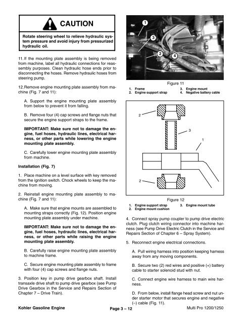
Figure 11<br />
1. Frame 3.<br />
2. Engine support strap 4.<br />
2<br />
4<br />
Engine mount<br />
Negative battery cable<br />
A. Support the engine mounting plate assembly<br />
from below to prevent it from falling.<br />
B. Remove four (4) cap screws and flange nuts that<br />
secure the engine support straps to the frame.<br />
2<br />
IMPORTANT: Make sure not to damage the engine,<br />
fuel hoses, hydraulic lines, electrical harness,<br />
or other parts while lowering the engine<br />
mounting plate assembly.<br />
C. Carefully lower engine mounting plate assembly<br />
from machine.<br />
Installation (Fig. 7)<br />
3<br />
1<br />
1. Place machine on a level surface with key removed<br />
from the ignition switch. Chock wheels to keep the machine<br />
from moving.<br />
2. Reinstall engine mounting plate assembly to machine<br />
(Fig. 7 and 11):<br />
A. Make sure that engine mounts are assembled to<br />
mounting straps correctly (Fig. 12). Position engine<br />
mounting plate assembly under machine.<br />
IMPORTANT: Make sure not to damage the engine,<br />
fuel hoses, hydraulic lines, electrical harness,<br />
or other parts while raising the engine<br />
mounting plate assembly.<br />
B. Carefully raise engine mounting plate assembly<br />
to machine frame.<br />
C. Secure engine mounting plate assembly to frame<br />
with four (4) cap screws and flange nuts.<br />
2<br />
Figure 12<br />
1. Engine support strap 3. Engine mount tube<br />
2. Engine mount cushion<br />
4. Connect spray pump coupler to pump drive electric<br />
clutch. Plug clutch wiring connector into machine harness<br />
(see Pump Drive Electric Clutch in the Service and<br />
Repairs Section of Chapter 6 – Spray System).<br />
5. Reconnect engine electrical connections.<br />
A. Pull wiring harness into position keeping harness<br />
away from any moving components.<br />
B. Secure two (2) red wires and positive (+) battery<br />
cable to starter solenoid stud with nut.<br />
3. Position key in pump drive gearbox shaft. Install<br />
transaxle drive shaft to pump drive gearbox (see Pump<br />
Drive Gearbox in the Service and Repairs Section of<br />
Chapter 7 – Drive Train).<br />
Kohler Gasoline Engine<br />
Page 3 – 12<br />
C. Connect engine wire harness to main wire harness.<br />
D. From below, install flange head screw and nut under<br />
starter motor that secures engine and negative<br />
(–) cable (Fig. 11).<br />
Multi Pro 1200/1250


