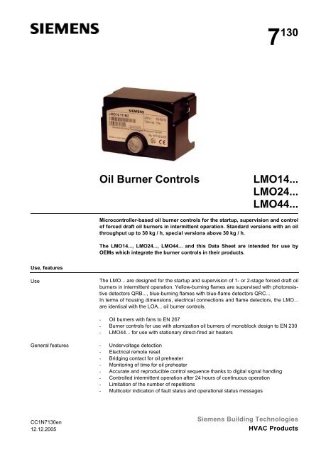
7130 Oil Burner Controls LMO14... LMO24... LMO44...
7130 Oil Burner Controls LMO14... LMO24... LMO44...
7130 Oil Burner Controls LMO14... LMO24... LMO44...

Create successful ePaper yourself
Turn your PDF publications into a flip-book with our unique Google optimized e-Paper software.
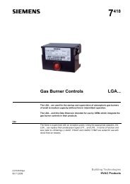
7 130<br />
<strong>Oil</strong> <strong>Burner</strong> <strong>Controls</strong><br />
<strong>LMO14.</strong>..<br />
<strong>LMO24.</strong>..<br />
<strong>LMO44.</strong>..<br />
Microcontroller-based oil burner controls for the startup, supervision and control<br />
of forced draft oil burners in intermittent operation. Standard versions with an oil<br />
throughput up to 30 kg / h, special versions above 30 kg / h.<br />
The <strong>LMO14.</strong>.., <strong>LMO24.</strong>.., <strong>LMO44.</strong>.. and this Data Sheet are intended for use by<br />
OEMs which integrate the burner controls in their products.<br />
Use, features<br />
Use<br />
The LMO... are designed for the startup and supervision of 1- or 2-stage forced draft oil<br />
burners in intermittent operation. Yellow-burning flames are supervised with photoresistive<br />
detectors QRB..., blue-burning flames with blue-flame detectors QRC...<br />
In terms of housing dimensions, electrical connections and flame detectors, the LMO...<br />
are identical with the LOA... oil burner controls.<br />
- <strong>Oil</strong> burners with fans to EN 267<br />
- <strong>Burner</strong> controls for use with atomization oil burners of monoblock design to EN 230<br />
- <strong>LMO44.</strong>.. for use with stationary direct-fired air heaters<br />
General features<br />
- Undervoltage detection<br />
- Electrical remote reset<br />
- Bridging contact for oil preheater<br />
- Monitoring of time for oil preheater<br />
- Accurate and reproducible control sequence thanks to digital signal handling<br />
- Controlled intermittent operation after 24 hours of continuous operation<br />
- Limitation of the number of repetitions<br />
- Multicolor indication of fault status and operational status messages<br />
CC1N<strong>7130</strong>en<br />
12.12.2005<br />
Siemens Building Technologies<br />
HVAC Products
Warning notes<br />
To avoid injury to persons, damage to property or the environment, the following<br />
warning notes should be observed!<br />
Do not open, interfere with or modify the unit!<br />
ARK21...<br />
• All activities (mounting, installation and service work, etc.) must be performed by<br />
qualified staff<br />
• Before performing any wiring changes in the connection area of the LMO..., completely<br />
isolate the burner control from the mains supply (all-polar disconnection)<br />
• Ensure protection against electric shock hazard by providing adequate protection<br />
for the burner control’s connection terminals<br />
• Each time work has been carried out (mounting, installation, service work, etc.),<br />
check to ensure that wiring is in an orderly state and make the safety checks as<br />
described in «Commissioning notes»<br />
• Press the lockout reset button / operation button or the AGK20… lockout reset button<br />
extension only manually (applying a force of no more than 10 N) without using<br />
any tools or pointed objects<br />
• Fall or shock can adversely affect the safety functions. Such units must not be put<br />
into operation, even if they do not exhibit any damage<br />
• When replacing LOA26... or LOA36..., any ARK21... remote lockout reset module<br />
or similar modules fitted in the burner or boiler must be removed<br />
Mounting notes<br />
• Ensure that the relevant national safety regulations are complied with<br />
Installation notes<br />
• Always run the high-voltage ignition cables separately while observing the greatest<br />
possible distances to the unit and to other cables<br />
• Install switches, fuses, earthing, etc., in compliance with local regulations<br />
• Ensure that the maximum permissible amperages will not be exceeded (refer to<br />
«Technical data»)<br />
• Do not feed external mains voltage to the control outputs of the unit. When testing<br />
the components controlled by the burner control (fuel valves, etc.), the LMO... may<br />
never be plugged in<br />
• Do not mix up live and neutral conductors<br />
Electrical connection of the flame detectors<br />
It is important to achieve practically disturbance- and loss-free signal transmission:<br />
• Never run the detector cable together with other cables<br />
– Line capacitance reduces the magnitude of the flame signal<br />
– Use a separate cable<br />
• Observe the maximum permissible lengths of the detector cables (refer to «Technical<br />
data»)<br />
2/13<br />
Siemens Building Technologies<br />
CC1N<strong>7130</strong>en<br />
HVAC Products 12.12.2005
Commissioning notes<br />
• When commissioning the plant or when doing maintenance work, make the following<br />
safety checks:<br />
Safety check<br />
a) <strong>Burner</strong> startup with flame detector darkened<br />
b) <strong>Burner</strong> startup with flame detector exposed<br />
to extraneous light<br />
c) <strong>Burner</strong> operation with simulated loss of<br />
flame; for that purpose, darken the flame<br />
detector during operation and maintain<br />
that state<br />
Anticipated response<br />
Lockout at the end of «TSA»<br />
Lockout after no more than 40<br />
seconds<br />
Repetition followed by lockout at<br />
the end of «TSA»<br />
Standards and certificates<br />
Conformity to EEC directives<br />
- Electromagnetic compatibility EMC (immunity)<br />
- Low-voltage directive<br />
89 / 336 / EEC<br />
73 / 23 / EEC<br />
ISO 9001: 2000<br />
Cert. 00739<br />
ISO 14001: 2004<br />
Cert. 38233<br />
Service notes<br />
• Use the KF8885 / KF8833 / KF8840 service adapters for short periods of time only<br />
Disposal notes<br />
The unit contains electrical and electronic components and must not be disposed of together<br />
with domestic waste.<br />
Local and currently valid legislation must be observed.<br />
Mechanical design<br />
The housing is made of impact-proof, heat-resistant and flame-retarding plastic.<br />
It is of plug-in design and engages audibly in the base.<br />
The housing accommodates the<br />
- microcontroller for the control sequence and the control relays for load control<br />
- electronic flame signal amplifier<br />
- lockout reset button with its integrated multicolor signal lamp (LED) for operational<br />
status and fault status messages and the socket for connecting the OCI400 interface<br />
adapter or the AGK20... lockout reset button extension<br />
Indication and<br />
diagnostics<br />
- Multicolor indication of operational status and fault status messages<br />
- Transmission of operational status and fault status messages and detailed service<br />
information via additional OCI400 interface adapter and ACS400 PC Windows software<br />
3/13<br />
Siemens Building Technologies<br />
CC1N<strong>7130</strong>en<br />
HVAC Products 12.12.2005
Type summary<br />
Type reference Mains<br />
voltage<br />
Standard versions<br />
Fuel <strong>Burner</strong> ¹) Remote<br />
Times<br />
Comparable type of<br />
valve capacity<br />
reset tw t1 / t1´ TSA t3 t3n<br />
stages<br />
max. min. max. min. max.<br />
t4 LOA... 4)<br />
min.<br />
<strong>LMO14.</strong>111B2 AC 230 V 1 < 30 kg / h • • 5 s 15 / 16 s 10 s 15 s 10 s --- LOA24.171B27<br />
LOA26.171B27 ²)<br />
LOA36.171A27 ²)<br />
<strong>LMO14.</strong>111B1 AC 110 V 1 < 30 kg / h • • 5 s 15 / 16 s 10 s 15 s 10 s --- LOA24.171B17<br />
<strong>LMO14.</strong>113B2 AC 230 V 1 < 30 kg / h • • 5 s 15 / 16 s 10 s 15 s 3 s --- LOA24.173A27 ³)<br />
<strong>LMO24.</strong>111B2 AC 230 V 2 < 30 kg / h • • 5 s 15 / 16 s 10 s 15 s 10 s 15 s LOA24.171B27<br />
LOA26.171B27 ²)<br />
LOA36.171A27 ²)<br />
<strong>LMO24.</strong>111B1 AC 110 V 2 < 30 kg / h • • 5 s 15 / 16 s 10 s 15 s 10 s 15 s LOA24.171B17<br />
<strong>LMO24.</strong>113B2 AC 230 V 2 < 30 kg / h • • 5 s 15 / 16 s 10 s 15 s 3 s 15 s LOA24.173A27 ³)<br />
<strong>LMO24.</strong>255B2 AC 230 V 2 30 kg/h • • 5 s 25 / 26 s 5 s 25 s 5 s 15 s ---<br />
Version for flash-steam generators<br />
<strong>LMO24.</strong>011B2 AC 230 V 2 < 30 kg / h • • 5 s 5 / 6 s 10 s 5 s 10 s 15 s LOA24.571C27<br />
Suited for direct-fired air heaters<br />
<strong>LMO44.</strong>255C2 AC 230 V 2 < / > 30kg / h • • 5 s 25 / 26 s 5 s 25 s 5 s 5 s LOA44.252A27<br />
Legend<br />
TSA Ignition safety time<br />
tw<br />
Waiting time<br />
t1<br />
Prepurge time<br />
t1’ Purge time<br />
t3<br />
Preignition time<br />
t3n Postignition time<br />
t4<br />
Interval from flame signal to release of «BV2»<br />
¹) Bridging contact for oil preheater<br />
²) No «SA» function<br />
³) In case of replacement, ignition transformer must be rewired from terminal 7<br />
(LOA...) to terminal 6 (LMO...)<br />
4) LMO... can replace LOA..., but the instructions given in the Data Sheet, other technical<br />
documentation and the specification must be followed<br />
4/13<br />
Siemens Building Technologies<br />
CC1N<strong>7130</strong>en<br />
HVAC Products 12.12.2005
Ordering<br />
<strong>Oil</strong> burner control (without plug-in base)<br />
Connection accessories for small burner controls<br />
- Plug-in base AGK11...<br />
- Cable holders AGK65..., AGK66, AGK67...<br />
- Cable strain relief elements for AGK67...<br />
Connection accessories for small burner controls<br />
- Plug-in base AGK13...<br />
- Plug-in housing AGK56...<br />
- Cover AGK68...<br />
refer to «Type summary»<br />
refer to Data Sheet N7201<br />
refer to Data Sheet N7203<br />
Flame detectors<br />
- Photoresistive detectors QRB1... refer to Data Sheet N7714<br />
- Blue-flame detectors QRC1... refer to Data Sheet N7716<br />
- Ionization probe supplied by thirds<br />
Diagnostic tool<br />
- Interface adapter OCI400<br />
- PC Windows software ACS400<br />
Demo case<br />
- For demonstrating the functions of burner controls<br />
(refer to User Manual B7989)<br />
refer to Data Sheet N7614<br />
KF8891<br />
Test adapter<br />
- For checking the functions of burner controls on the burner<br />
- With switch for manual startup of the burner<br />
- With switch for simulating the oil preheater’s release contact<br />
- With 2 pairs of jacks for measuring the flame detector current<br />
(refer to Operating Instructions B7986)<br />
Test adapter<br />
- For checking the functions of burner controls on the burner<br />
- With signal lamps for program indication<br />
- With one pair of jacks for measuring the flame detector current<br />
Test adapter<br />
- For checking the functions of burner controls on the burner<br />
- With signal lamps for program indication<br />
- With on / off switch for simulating the flame signal<br />
- With holes for checking the control voltages at the tabs of the burner control<br />
- With one pair of jacks for measuring the flame detector’s resistance<br />
KF8885<br />
KF8833<br />
KF8840<br />
Extension of lockout reset button<br />
- Extension 19 mm AGK20.19<br />
- Extension 43 mm AGK20.43<br />
- Extension 55 mm AGK20.55<br />
5/13<br />
Siemens Building Technologies<br />
CC1N<strong>7130</strong>en<br />
HVAC Products 12.12.2005
Technical data<br />
General unit data<br />
Mains voltage AC 230 V +10 % / -15 %<br />
AC 110 V +10 % / -15 %<br />
Mains frequency 50...60 Hz ±6 %<br />
External primary fuse (Si)<br />
6.3 A (slow)<br />
Power consumption<br />
12 VA<br />
Perm. mounting orientation<br />
optional<br />
Weight<br />
approx. 200 g<br />
Safety class<br />
I<br />
Degree of protection<br />
IP 40 (to be ensured through mounting)<br />
Perm. cable lengths<br />
max. 3 m at a line capacitance of 100 pF/m<br />
Detector cable laid separately<br />
20 m<br />
Remote reset laid separately<br />
20 m<br />
Perm. current at cosϕ ≥ 0.6 <strong>LMO14.</strong>.. <strong>LMO24.</strong>.. <strong>LMO44.</strong>..<br />
Terminal 1 max. 5 A max. 5 A max. 5 A<br />
Terminals 3 and 8 max. 3 A max. 5 A max. 5 A<br />
Terminals 4 and 5 max. 1 A max. 1 A max. 1 A<br />
Terminal 6 max. 1 A max. 1 A max. 2 A<br />
Terminal 10 max. 1 A max. 1 A max. 1 A<br />
Environmental<br />
conditions<br />
Storage DIN EN 60721-3-1<br />
Climatic conditions<br />
class 1K3<br />
Mechanical conditions<br />
class 1M2<br />
Temperature range -20...+60 °C<br />
Humidity<br />
< 95 % r.h.<br />
Transport DIN EN 60 721-3-2<br />
Climatic conditions<br />
class 2K2<br />
Mechanical conditions<br />
class 2M2<br />
Temperature range -20...+60 °C<br />
Humidity<br />
< 95 % r.h.<br />
Operation DIN EN 60 721-3-3<br />
Climatic conditions<br />
class 3K3<br />
Mechanical conditions<br />
class 3M3<br />
Temperature range<br />
- <strong>LMO14.</strong>.. / <strong>LMO24.</strong>..<br />
-5...+60 °C<br />
- <strong>LMO44.</strong>..<br />
-20...+60 °C<br />
Humidity<br />
< 95 % r.h.<br />
Condensation, formation of ice and ingress of water are not permitted!<br />
Flame supervision with<br />
QRB... or QRC...<br />
Green LED for operational<br />
status indication<br />
Detector current<br />
required<br />
(with flame)<br />
Perm. detector<br />
current<br />
(without flame)<br />
Possible detector current<br />
with flame<br />
(typically)<br />
QRB... ¹) min. 45 µA max. 5.5 µA max. 100 µA<br />
QRC... ¹) min. 70 µA max. 5.5 µA max. 100 µA<br />
Detector current in operation:<br />
- Flame signal instable<br />
- Green LED flashing<br />
Detector current in operation:<br />
- Flame signal stable<br />
- Green LED steady on<br />
QRB... ¹) < 45 µA > 45 µA<br />
QRC... ¹) < 45 µA > 45 µA<br />
¹) The values given in the table above only apply under the following conditions:<br />
- Mains voltage AC 230 V<br />
- Ambient temperature 23 °C<br />
6/13<br />
Siemens Building Technologies<br />
CC1N<strong>7130</strong>en<br />
HVAC Products 12.12.2005
Technical data (cont´d)<br />
Measuring circuit<br />
for detector current<br />
QRB...<br />
11 12 LMO...<br />
<strong>7130</strong>v01/0700<br />
bl<br />
sw<br />
+<br />
QRB...<br />
µA DC<br />
QRC...<br />
11 12 1 LMO...<br />
<strong>7130</strong>v02/0700<br />
bl sw br<br />
+<br />
QRC1...<br />
µA DC<br />
Legend<br />
µA DC DC microammeter<br />
with an internal<br />
resistance of<br />
Ri = max. 5 kΩ<br />
bl Blue<br />
sw Black<br />
br Brown<br />
As an alternative to detector current measurement, the diagnostic tool OCI400 /<br />
ACS400 can be used. In that case, the DC microammeter is not required.<br />
7/13<br />
Siemens Building Technologies<br />
CC1N<strong>7130</strong>en<br />
HVAC Products 12.12.2005
Function<br />
Preconditions for<br />
startup<br />
Undervoltage<br />
Time supervision<br />
oil preheater<br />
Controlled intermittent<br />
operation<br />
Control sequence in<br />
the event of fault<br />
• <strong>Burner</strong> control is reset<br />
• All contacts in the line are closed and there is demand for heat<br />
• No undervoltage<br />
• Flame detector is darkened and there is no extraneous light<br />
• Safety shutdown from the operating position takes place should mains voltage drop<br />
below about AC 165 V (UN = AC 230 V)<br />
• Restart is initiated when mains voltage exceeds about AC 175 V (UN = AC 230 V)<br />
If the oil preheater’s release contact does not close within 10 minutes, the burner control<br />
will initiate lockout.<br />
After no more than 24 hours of continuous operation, the burner control will initiate<br />
automatic controlled shutdown followed by a restart.<br />
If lockout occurs, the outputs for the fuel valves, the burner motor and the ignition<br />
equipment will immediately be deactivated (< 1 second).<br />
Cause<br />
Mains failure<br />
Voltage has fallen below the undervoltage<br />
threshold<br />
Extraneous light during «t1»<br />
Extraneous light during «tw»<br />
No flame at the end of «TSA»<br />
Loss of flame during operation<br />
<strong>Oil</strong> preheater’s release contact does not<br />
close within 10 minutes<br />
Response<br />
Restart<br />
Restart<br />
Lockout at the end of «t1»<br />
Prevention of startup, lockout after 40 seconds<br />
at the latest<br />
Lockout at the end of «TSA»<br />
Max. 3 repetitions, followed by lockout<br />
Lockout<br />
In the event of lockout, the LMO... remains locked and the red signal lamp (LED) will light<br />
up. The burner control can immediately be reset. This state is also maintained in the case<br />
of mains failure.<br />
Resetting the<br />
burner control<br />
Ignition program with<br />
<strong>LMO14.</strong>113B2 and<br />
<strong>LMO24.</strong>113B2<br />
Limitation of repetitions<br />
When lockout occurs, the burner control can immediately be reset. To do this, press the<br />
lockout reset button for about 1 second (< 3 seconds). The LMO... can only be reset<br />
when all contacts in the line are closed and when there is no undervoltage.<br />
If the flame is lost during «TSA», the burner will be reignited, but only until the end of<br />
«TSAmax». This means that several ignition attempts can be made during «TSA» (refer<br />
to «Control sequence»).<br />
If the flame is lost during operation, a maximum of 3 repetitions can be made. If the<br />
flame is lost for the fourth time during operation, the burner will initiate lockout. The<br />
repetition count is restarted each time controlled switching on by «R» takes place.<br />
8/13<br />
Siemens Building Technologies<br />
CC1N<strong>7130</strong>en<br />
HVAC Products 12.12.2005
Operation, display, diagnostics<br />
Operation<br />
EK<br />
<strong>7130</strong>z05/0700<br />
Lockout reset button «EK...» is the key operating element for resetting<br />
the burner control and for activating / deactivating the diagnostic functions.<br />
<strong>7130</strong>z06e/0700<br />
Red<br />
Yellow<br />
Green<br />
LED<br />
The multicolor signal lamp (LED) in the lockout reset button is the key<br />
indicating element for both visual diagnostics and interface diagnostics.<br />
Both «EK...» and LED are located under the transparent cover of the lockout reset button.<br />
There are 2 diagnostic choices:<br />
1. Visual diagnostics: Operational status indication or diagnostics of the cause of<br />
fault.<br />
2. Interface diagnostics: With the help of the interface adapter OCI400 and PC software<br />
ACS400 or flue gas analyzers of different makes (refer to Data Sheet N7614).<br />
Visual diagnostics:<br />
In normal operation, the different operating states are indicated in the form of color<br />
codes according to the color code table given below. Interface diagnostics is activated<br />
by pressing the lockout reset button for at least 3 seconds (refer to Data Sheet N7614).<br />
If, by accident, interface diagnostics has been activated, in which case the slightly red<br />
light of the signal lamp flickers, it can be deactivated by pressing again the lockout reset<br />
button for at least 3 seconds. The instant of switching over is indicated by a yellow<br />
light pulse.<br />
Operating position<br />
Visual diagnostics<br />
> 3 s<br />
Operating position<br />
Interface diagnostics<br />
PC / analyzer<br />
Color code table<br />
xxxxxxxx<br />
xxxxxxxx<br />
xxxxxxxx<br />
xxxxxxxx<br />
xxxxxxxx<br />
xxxxxxxx<br />
EK<br />
<strong>7130</strong>z01e/0602<br />
Operational status<br />
indication<br />
Legend<br />
During startup, status indication takes place according to the following table:<br />
Color code table for multicolor signal lamp (LED)<br />
Status Color code Color<br />
Waiting time «tw», other waiting states ........................................ Off<br />
<strong>Oil</strong> preheater on, waiting time «tw» •........................................ Yellow<br />
Ignition phase, ignition controlled • • • • • • Flashing yellow<br />
Operation, flame o.k. ........................................ Green<br />
Operation, flame not o.k. Flashing green<br />
Extraneous light on burner startup Green-red<br />
Undervoltage • • • • • Yellow-red<br />
Fault, alarm ....................................... Red<br />
Error code output (refer to «Error code table»)<br />
Flashing red<br />
<br />
Interface diagnostics Red flicker light<br />
...... Steady on Red<br />
Off • Yellow<br />
Green<br />
9/13<br />
Siemens Building Technologies<br />
CC1N<strong>7130</strong>en<br />
HVAC Products 12.12.2005
Operation, display, diagnostics (cont´d)<br />
Diagnostics of the<br />
cause of fault<br />
After lockout, the red fault signal lamp remains steady on. In that condition, the visual<br />
diagnostics of the cause of fault according to the error code table can be activated by<br />
pressing the lockout reset button for more than 3 seconds. Pressing the reset button<br />
again for at least 3 seconds, the interface diagnostics will be activated. Interface diagnostics<br />
works only if the AGK20… lockout reset button extension is not fitted.<br />
For more detailed information, refer to Data Sheet N7614.<br />
The following sequence activates the diagnostics of the cause of fault:<br />
OCI400<br />
Lockout position Lockout position Lockout position<br />
Visual diagnostics<br />
Interface diagnostics<br />
On<br />
Flashing<br />
PC / analyzer<br />
EK<br />
> 3 s<br />
Error code table<br />
xxxxxxxx<br />
xxxxxxxx<br />
xxxxxxxx<br />
xxxxxxxx<br />
xxxxxxxx<br />
xxxxxxxx<br />
EK<br />
> 3 s<br />
<strong>7130</strong>z04e/0602<br />
EK<br />
< 3 s<br />
Reset<br />
Red blink code of signal<br />
lamp (LED)<br />
2 blinks<br />
hh<br />
3 blinks<br />
hhh<br />
4 blinks<br />
hhhh<br />
5 blinks<br />
hhhhh<br />
6 blinks<br />
hhhhhh<br />
7 blinks<br />
hhhhhhh<br />
8 blinks<br />
hhhhhhhh<br />
9 blinks<br />
hhhhhhhhh<br />
10 blinks<br />
hhhhhhhhhh<br />
10 blinks<br />
hhhhhhhhhh<br />
Error code table<br />
«AL» at Possible cause<br />
term. 10<br />
On No establishment of flame at the end of «TSA»<br />
- Faulty or soiled fuel valves<br />
- Faulty or soiled flame detector<br />
- Poor adjustment of burner, no fuel<br />
- Faulty ignition equipment<br />
On Free<br />
On<br />
On<br />
On<br />
On<br />
On<br />
On<br />
Extraneous light on burner startup<br />
Free<br />
Free<br />
Too many losses of flame during operation (limitation<br />
of the number of repetitions)<br />
- Faulty or soiled fuel valves<br />
- Faulty or soiled flame detector<br />
- Poor adjustment of burner<br />
Time supervision oil preheater<br />
- <strong>Oil</strong> preheater failed 5 times during prepurging<br />
Free<br />
Off Wiring fault or internal fault, output contacts, o-<br />
ther faults<br />
On 3 times temporary fault of the output contacts<br />
During the time the cause of fault is diagnosed, the control outputs are deactivated burner<br />
remains shut down.<br />
The diagnostics of the cause of fault is quit and the burner switched on again by resetting<br />
the burner control. Press the lockout reset button for about 1 second (< 3 seconds).<br />
10/13<br />
Siemens Building Technologies<br />
CC1N<strong>7130</strong>en<br />
HVAC Products 12.12.2005
Connection diagram and internal diagram <strong>LMO14.</strong>..<br />
Control sequence <strong>LMO14.</strong>..<br />
EK1<br />
LED<br />
µC1<br />
µC control<br />
µC2<br />
R<br />
W<br />
A´ A B C D<br />
SB tw<br />
OH<br />
1<br />
8<br />
K1<br />
K2<br />
FSV<br />
OW<br />
3<br />
K3<br />
1 2 10 8 3<br />
kbr<br />
6 7 4 5 9 11 12<br />
SB<br />
8 3<br />
R<br />
OW<br />
EK2<br />
QRB<br />
W<br />
AL<br />
OH<br />
N<br />
QRC<br />
Si<br />
1<br />
bl sw<br />
L<br />
N<br />
M Z BV1<br />
br<br />
<strong>7130</strong>a01e/0700<br />
M<br />
BV1<br />
t1<br />
Z<br />
t3<br />
FS<br />
Only with <strong>LMO14.</strong>113B2: re-ignition<br />
t3n<br />
Z<br />
FS<br />
<strong>7130</strong>d02e/1002<br />
t3n<br />
TSA<br />
t3n<br />
3<br />
4<br />
6<br />
11<br />
12<br />
6<br />
11<br />
12<br />
Connection diagram and internal diagram <strong>LMO24.</strong>..<br />
Control sequence <strong>LMO24.</strong>..<br />
EK1<br />
LED<br />
µC1<br />
µC control<br />
µC2<br />
R<br />
W<br />
A´ A B C D<br />
SB tw<br />
OH<br />
1<br />
8<br />
K2<br />
K1<br />
FSV<br />
K3<br />
K4<br />
1 2 10 8 3 6 7 4 5 9 11 12<br />
kbr<br />
SB<br />
8 3<br />
R<br />
QRB<br />
OW<br />
EK2<br />
W<br />
AL<br />
OH<br />
BV2<br />
N<br />
Si<br />
1<br />
L<br />
M Z BV1<br />
N<br />
<strong>7130</strong>a02e/0700<br />
QRC<br />
bl sw<br />
br<br />
OW<br />
M<br />
BV2<br />
Z<br />
FS<br />
t1´<br />
BV1 4<br />
t4<br />
Only with <strong>LMO24.</strong>113B2: re-ignition<br />
Z<br />
t1<br />
t3<br />
t3n<br />
t3n<br />
TSA<br />
t3n<br />
3<br />
3<br />
5<br />
6<br />
11<br />
12<br />
6<br />
FS<br />
<strong>7130</strong>d03e/1102<br />
11<br />
12<br />
Connection diagram and internal diagram LMO44…<br />
Control sequence LMO44…<br />
EK1<br />
µC1 µC-Steuerung µC2<br />
LED<br />
K2<br />
K1<br />
FSV<br />
K3<br />
K4<br />
1 2 10 8 3 6 7 4 5 9 11 12<br />
kbr<br />
SB<br />
8 3<br />
R<br />
QRB<br />
OW<br />
EK2<br />
W<br />
AL<br />
OH<br />
BV2<br />
N<br />
Si<br />
1<br />
L<br />
M Z BV1<br />
N<br />
<strong>7130</strong>a04/1105<br />
QRC<br />
bl sw<br />
br<br />
R<br />
W<br />
A´ A B C D<br />
SB tw<br />
OH<br />
OW<br />
M<br />
BV2<br />
Z<br />
FS<br />
t1´<br />
t1<br />
BV1 4<br />
t4<br />
t3<br />
t3n<br />
TSA<br />
<strong>7130</strong>d05/1105<br />
1<br />
8<br />
3<br />
3<br />
5<br />
6<br />
11<br />
12<br />
11/13<br />
Siemens Building Technologies<br />
CC1N<strong>7130</strong>en<br />
HVAC Products 12.12.2005
Legend<br />
AL<br />
BV...<br />
EK1<br />
EK2<br />
FS<br />
FSV<br />
K...<br />
kbr<br />
LED<br />
M<br />
OW<br />
OH<br />
QRB...<br />
QRC...<br />
R<br />
SB<br />
Si<br />
W<br />
Z<br />
Alarm device<br />
Fuel valve<br />
Lockout reset button<br />
Remote lockout reset button<br />
Flame signal<br />
Flame signal amplifier<br />
Contacts of control relay<br />
Cable link (required only when no oil preheater is used)<br />
3-color signal lamp<br />
<strong>Burner</strong> motor<br />
Release contact of oil preheater<br />
<strong>Oil</strong> preheater<br />
Photoresistive flame detector<br />
Blue-flame detector<br />
bl = blue, br = brown, sw = black<br />
Control thermostat or pressurestat<br />
Safety limit thermostat<br />
External primary fuse<br />
Limit thermostat or pressure switch<br />
Ignition transformer<br />
TSA Ignition safety time<br />
tw<br />
Waiting time<br />
t1<br />
Prepurge time<br />
t1´ Purge time<br />
t3<br />
Preignition time<br />
t3n<br />
Postignition time<br />
t4<br />
Interval from flame signal to release of «BV2»<br />
A´ Start of startup sequence with burners using an «OH»<br />
A<br />
Start of startup sequence with burners using no «OH»<br />
B<br />
Time of flame establishment<br />
C<br />
Operating position<br />
D<br />
Controlled shutdown by «R»<br />
Control signals<br />
Required input signals<br />
Perm. input signals<br />
µC1 Microcontroller 1<br />
µC2 Microcontroller 2<br />
12/13<br />
Siemens Building Technologies<br />
CC1N<strong>7130</strong>en<br />
HVAC Products 12.12.2005
Dimensions<br />
Dimensions in mm<br />
LMO...<br />
22<br />
5,2<br />
53,9<br />
88<br />
41,6<br />
91<br />
<strong>7130</strong>m05/0904<br />
47,2<br />
62,5<br />
<strong>7130</strong>m04/1004<br />
Plug-in base AGK11... / AGK13...<br />
9<br />
LMO... with extension of<br />
lockout reset button<br />
AGK20...<br />
7,44 L<br />
Type reference Length «L» in mm<br />
AGK20.20 19<br />
AGK20.43 43<br />
AGK20.55 55<br />
© 2005 Siemens Building Technologies HVAC Products GmbH<br />
Subject to change!<br />
13/13<br />
Siemens Building Technologies<br />
CC1N<strong>7130</strong>en<br />
HVAC Products 12.12.2005