Lecture 11: RF Power Amplifiers Amplifier parameter definitions η
Lecture 11: RF Power Amplifiers Amplifier parameter definitions η
Lecture 11: RF Power Amplifiers Amplifier parameter definitions η

You also want an ePaper? Increase the reach of your titles
YUMPU automatically turns print PDFs into web optimized ePapers that Google loves.
• The PA designer has to take the small cell and scale it by tens,<br />
even hundreds, to “build” a power transistor.<br />
• Such a scaling, unfortunately, is not a simple set of electrical nodal<br />
connections.<br />
• Secondary phenomena associated with large periphery devices:<br />
– Nonuniform thermal effects --- against the customary assumptions made<br />
about equal currents and voltages across an array of “identical” circuit<br />
elements.<br />
– Multiple parallel connections also can cause mutual coupling between<br />
bondwires.<br />
• The most difficult part of the scale-up <strong>RF</strong> power transistor models<br />
is the difficulty of putting the model and the device through simple<br />
comparative tests.<br />
– DC I-V curves: curve tracers are too slow for <strong>RF</strong> power transistors. The<br />
measured I-V characteristics usually include the transient junction heating<br />
effects, which will not occur to any significant extent during an <strong>RF</strong> cycle.<br />
ELEC518, Kevin Chen, HKUST 13<br />
– Pulsed I-V measurement is attracting increasing interests, but<br />
the measurement system is expensive --- usually provide I-V<br />
data quite different from that obtained using curve tracers ---<br />
results in “dispersion”<br />
– The impedances are typically so low, compared to a 50Ω<br />
reference, that even simple linear s-<strong>parameter</strong> measurement is<br />
fraught with calibration problems --- pre-matching --- additional<br />
challenging calibration problems in de-embedding the matching<br />
networks.<br />
ELEC518, Kevin Chen, HKUST 14<br />
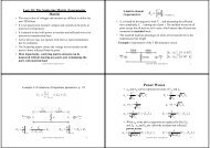
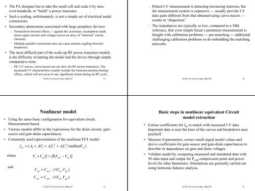
Nonlinear model<br />
• Using the same basic configuration for equivalent circuit.<br />
Measurement-based.<br />
• Various models differ in the expressions for the drain current, gatesource<br />
and gate-drain capacitances.<br />
• Commonly used representation of the nonlinear FET model<br />
2 3<br />
I = ( A + AV + A V + AV ) tanh( αV<br />
)<br />
where<br />
and<br />
ds<br />
0 1 1 2 1 3 1<br />
ds<br />
V = V [1 + β ( V<br />
−V<br />
1 gs<br />
dso ds<br />
C<br />
C<br />
gs<br />
gd<br />
= C<br />
= C<br />
gso<br />
gdo<br />
⋅ f ( Vgs,<br />
Vgd<br />
)<br />
⋅ f V , V )<br />
(<br />
gs gd<br />
)]<br />
Basic steps in nonlinear equivalent Circuit<br />
model extraction<br />
• Extract coefficients for I ds to match with measured I-V data.<br />
Important data is near the knee of the curves and breakdown near<br />
pinchoff.<br />
• Measure S-<strong>parameter</strong>s, extract small-signal model values and<br />
derive coefficients for gate-source and gate-drain capacitances to<br />
describe its dependence on gate and drain voltages.<br />
• Validate model by comparing measured and simulated data with<br />
50 ohm input and output for P 1dB compression point and power<br />
levels for other harmonics. Simulations are generally carried out<br />
using harmonic balance analysis.<br />
ELEC518, Kevin Chen, HKUST 15<br />
ELEC518, Kevin Chen, HKUST 16