100-300 Specifications & Technical Data PDF - Neptune-Benson
100-300 Specifications & Technical Data PDF - Neptune-Benson
100-300 Specifications & Technical Data PDF - Neptune-Benson

Create successful ePaper yourself
Turn your PDF publications into a flip-book with our unique Google optimized e-Paper software.
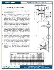
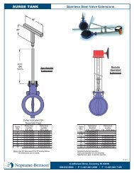
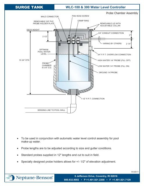
SURGE TANK<br />
WLC-<strong>100</strong> & <strong>300</strong> Water Level Controller<br />
MALE CONNECTOR<br />
REMOVABLE 3/8” PVC<br />
PROBE HOLDER PLATE<br />
PAN HEAD SCREW<br />
CRIMP RING<br />
Probe Chamber Assembly<br />
REMOVABLE LID WITH<br />
ADJUSTABLE COLLAR<br />
DECK HEIGHT<br />
2 1/2”<br />
3/4” CONDUIT CONNECTION<br />
2”<br />
WIRING BY OTHERS<br />
2 1/4”<br />
OPTIMUM<br />
POOL WATER<br />
LEVEL<br />
3/4” F.P.T. OVERFLOW CONNECTION<br />
15 3/4” STD.<br />
PROBE<br />
CHAMBER<br />
8 5 /8” O.D.<br />
HIGH WATER 1/4” PROBE (FILL OFF)<br />
LOW WATER 1/4” PROBE (FILL ON)<br />
GROUND 1/4”PROBE<br />
1 1/2” F.P.T. CONNECTION<br />
SENSING LINE TO POOL WALL<br />
• To be used in conjunction with automatic water level control assembly for pool<br />
make-up water.<br />
• Probe lengths are to be adjusted according to size and gutter conditions.<br />
• Standard probes supplied in 12" lengths and cut to suit in field.<br />
• Specially designed probe holders allows for +/- 1/2" of elevation adjustment.<br />
R-5/5/11<br />
6 Jefferson Drive, Coventry, RI 02816<br />
800.832.8002 • P +1.401.821.2200 • F +1.401.821.7129
AUTOMATIC MAKE-UP WATER LEVEL CONTROLLER—WLC-<strong>100</strong><br />
A. Pool water level shall be maintained by an automatic make-up level controller Model WLC-<strong>100</strong>.<br />
B. Controller package shall consist of a PVC chamber to house stainless steel probes, a liquid level<br />
relay and delay timer, 110v 24-hour timer and terminal board.<br />
C. Water level shall be controlled by the use of a three-probe electrode system, one for high level, one<br />
for low level and one ground. Electrodes shall be T316 stainless steel connected to a UL approved<br />
probe holder. A mechanical linkage or float operated system will not be acceptable.<br />
D. Probes and holders shall be housed in a PVC chamber consisting of an 8", schedule 80 PVC pipe.<br />
Chamber shall be sized to accommodate desired range of water level variation and shall be complete<br />
with removable cover and adjustable collar suitable for deck level installation. A 1 ½", equalizing<br />
line shall be connected from the bottom of the chamber to the pool wall.<br />
E. Probes shall be mounted on a readily removable plastic disk within the chamber. Probe connectors<br />
shall be protected with 90º molded plastic holders. Probe holders allow for +/- ½" of elevation<br />
adjustment.<br />
F. Wiring from the probes shall be connected to a UL approved relay mounted within the Control<br />
Panel.<br />
G. A 24 hour, 110v time clock shall be provided to allow for variable time settings of operation for the<br />
WLC system. Clock shall be provided with a manual override.<br />
H. Solenoid valve size shall be as indicated on drawing, N.C., slow closing.
AUTOMATIC MAKE-UP WATER LEVEL CONTROLLER—WLC-<strong>300</strong><br />
A. Pool water level shall be maintained by an automatic water level controller Model WLC-<strong>300</strong>.<br />
B. Controller package shall consist of a PVC probe chamber, stainless steel probes, and a solid state<br />
relay with NEMA 1 enclosure. Unit shall be <strong>Neptune</strong>-<strong>Benson</strong> Model WLC-<strong>300</strong> water level<br />
controller or approved equal.<br />
C. Water level shall be controlled by the use of a three probe electrode system; high level, low level and<br />
ground.<br />
D. Probes and holder shall be housed in a PVC chamber consisting of an 8" schedule 80 PVC pipe. The<br />
chamber is sized to accommodate the desired range of water level variation and shall be complete<br />
with a removable cover and adjustable collar suitable for deck level installation. A 1 ½" line shall be<br />
connected to the bottom of the probe chamber from the pool wall to reflect the water level in the<br />
pool.<br />
E. Probes shall be mounted on a readily removable plastic disc within the probe chamber. Probe<br />
connectors shall be protected with 90º molded plastic holders. Probe holders allow for +/- ½" of<br />
elevation adjustment.<br />
F. Wiring from the probes shall be connected to the relay that is to be mounted within a NEMA 1<br />
enclosure.<br />
G. Unit shall be suitable to activate any 110 volt or 230 volt circuit for solenoid valve, pump or other<br />
method of providing makeup water.<br />
H. Solenoid valve size shall be as indicated on drawing, N.C., slow closing.