Specifications & Technical Data PDF - Neptune-Benson
Specifications & Technical Data PDF - Neptune-Benson
Specifications & Technical Data PDF - Neptune-Benson

You also want an ePaper? Increase the reach of your titles
YUMPU automatically turns print PDFs into web optimized ePapers that Google loves.
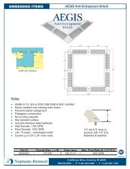
PART 2 - FILTER SYSTEM<br />
FILTER SYSTEM REQUIREMENTS<br />
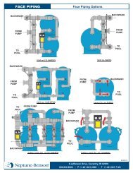
1. The system shall be supplied complete by the manufacturer and shall include: internals, face piping<br />
and valves, gauge panel with tubing and petcocks, sight glass, air relief connection, bottom drain<br />
connection with internal strainer.<br />
2. System shall be fabricated and fully assembled at the manufacturer's plant for pressure testing and<br />
dimensional verification. System shall be knocked down for shipping purposes in subassemblies for<br />
minimum field assembly. Internal manifold and lateral piping shall be factory installed and shipped<br />
in place.<br />
FILTER SYSTEM CAPACITY<br />
A. The system capacity, size, performance and model number shall be as shown on the drawings.<br />
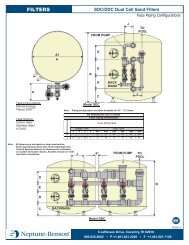
HORIZONTAL FIBERGLASS FILTER TANK<br />
A. The equipment described herein shall be products of a manufacturer regularly engaged in the<br />
fabrication of pressure vessels for at least 15 years.<br />
B. The filter tank shall be suitable for 50 psi working pressure, hydrostatically tested to 1.1 x working<br />
pressure and designed with a 4:1 safety factor.<br />
C. Saddle style bases (2) shall be provided for tank support. Systems which incorporate stacked tanks<br />
shall include similar bases and mounting saddles for the upper vessel. Access to the tank shall be<br />
provided by a 14” x 18” manhole with a two bolt, 4 point yoke. Manhole seal shall be complete with<br />
one piece ¼” neoprene gasket and positioned so that internal pressure from the filter will augment<br />
the seal. Externally mounted bolt-on covers will not be accepted.<br />
D. Drain out system shall consist of one (1) 3/4" fiberglass coupling mounted to the tank bottom. Each<br />
coupling to be fitted with a slotted PVC sand retainer. Air relief connection shall be one (1) 3/4"<br />
coupling provided on top of the tank. Bulkhead fittings will not be accepted.<br />
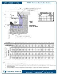
E. Each filter tank shall be equipped with the necessary flanges and connections for the internal and<br />
external piping. Connections shall be comprised of 1" minimum thickness fiberglass flanges with<br />
ANSI standard 150 lb. bolt pattern. Connections requiring bolt-thru hardware will not be accepted.<br />
F. The resin used shall be a commercial grade, premium corrosion resistant vinylester that has been<br />
evaluated in a laminate by test in accordance with ASTM C-581 in service comparable to the<br />
intended service and recommended for this service by the manufacturer. Other generic types of resin<br />
such as isophthalics or general purpose polyester resins shall not be acceptable.<br />
G. Ultraviolet absorbers shall be added to the exterior surface for improved exterior resistance.