
You also want an ePaper? Increase the reach of your titles
YUMPU automatically turns print PDFs into web optimized ePapers that Google loves.
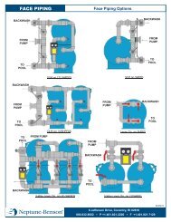
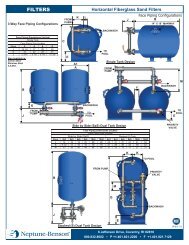
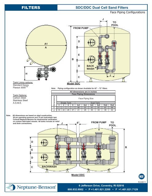
FILTERS<br />
<strong>SDC</strong>/DDC Dual Cell Sand Filters<br />
Face Piping Configurations<br />
FROM PUMP<br />
J<br />
TO<br />
POOL<br />
A1<br />
A<br />
D<br />
B<br />
E<br />
D<br />
BACK<br />
WASH<br />
H<br />
C<br />
J<br />
Tank Lining options:<br />
Standard Epoxy<br />
Flexsol 3000 TM<br />
Tank Options:<br />
Carbon Steel<br />
Stainless Steel<br />
A.S.M.E.<br />
Note:<br />
Dimensions<br />
Model <strong>SDC</strong><br />
Piping configuration as shown Available for 42” – 72” filters<br />
All dimensions are in inches<br />
Face Piping Dimensions<br />
Face Piping Size<br />
Single Tank<br />
Dual Tank<br />
3 4 6 8 4x3 6x4 6x6 8x6 10x6 10x8<br />
H - - - - 26 31 41 41 41 54<br />
J 19 22 28 37 21 26 30 33 39 42<br />
Note:<br />
All dimensions are based on steel construction,<br />
50 psi operating pressure and 75 psi hydrostatic test.<br />
Consult <strong>Neptune</strong>-<strong>Benson</strong> for dimensional verification<br />
on custom fabricated vessels. All tanks include air relief<br />
and drain connections.<br />
J<br />
6”<br />
FROM PUMP TO<br />
POOL<br />
D<br />
E<br />
B<br />
D<br />
C<br />
BACKWASH<br />
Model DDC<br />
6 Jefferson Drive, Coventry, RI 02816<br />
800.832.8002 • P +1.401.821.2200 • F +1.401.821.7129<br />
R-5/9/11
FILTERS<br />
<strong>SDC</strong>/DDC Dual Cell Sand Filters<br />
Physical Capacity and Dimensional Information<br />
AIR<br />
RELIEF<br />
14”X18”<br />
MANHOLE<br />
OVERDRAIN MANIFOLD<br />
D<br />
UNDERDRAIN MANIFOLD<br />
B<br />
E<br />
A1<br />
A<br />
D<br />
C<br />
TANK DRAIN<br />
Filter Model<br />
Number<br />
Tank<br />
Conn<br />
Filter<br />
Area<br />
(SF)<br />
Flow<br />
Capacity<br />
(GPM)<br />
Filter<br />
All dimensions are in inches<br />
Rate<br />
(GPM/SF) A* A1* B C D E F* G*<br />
Tank<br />
Shipping<br />
Weight<br />
(LBS)<br />
Operating<br />
Weight<br />
(LBS)<br />
42 <strong>SDC</strong>-4 3 19.2 96-384 5-20 42 42 3/8 90 16 1/16 24 3/4 11 1/2 3/16 3/16 1100 7689<br />
48 <strong>SDC</strong>-3 3 25.1 126-402 5-16 48 48 3/8 92 1/2 16 13/16 24 3/4 11 1/2 3/16 3/16 1250 9821<br />
48 <strong>SDC</strong>-4 4 25.1 403-502 17-20 48 48 3/8 92 1/2 17 13/16 23 3/4 12 1/2 3/16 3/16 1300 9821<br />
54 <strong>SDC</strong>-3 3 31.8 159-382 5-12 54 54 3/8 94 3/8 17 13/16 24 3/4 11 1/2 1/4 3/16 1600 13144<br />
54 <strong>SDC</strong>-4 4 31.8 383-636 13-20 54 54 3/8 94 3/8 18 13/16 23 3/4 12 1/2 1/4 3/16 1650 13144<br />
60 <strong>SDC</strong>-4 4 39.3 197-786 5-20 60 60 3/8 95 18 5/8 23 3/4 12 1/2 1/4 3/16 1900 16068<br />
66 <strong>SDC</strong>-4 4 47.5 238-713 5-15 66 66 1/2 96 1/2 19 3/8 23 3/4 12 1/2 1/4 1/4 2400 19262<br />
66 <strong>SDC</strong>-6 6 47.5 714-956 16-20 66 66 1/2 96 1/2 20 3/8 21 3/4 14 1/2 1/4 1/4 2500 19262<br />
72 <strong>SDC</strong>-4 4 56.5 283-678 5-12 72 72 1/2 98 20 3/16 23 3/4 12 1/2 1/4 1/4 2700 24000<br />
72 <strong>SDC</strong>-6 6 56.5 679-1130 13-20 72 72 1/2 98 21 3/16 21 3/4 14 1/2 1/4 1/4 2800 24000<br />
78 <strong>SDC</strong>-6 6 66.4 332-1328 5-20 78 78 1/2 100 22 1/8 21 3/4 14 1/2 5/16 1/4 3300 28653<br />
84 <strong>SDC</strong>-6 6 77 385-1540 5-20 84 84 1/2 101 1/2 22 15/16 21 3/4 14 1/2 5/16 1/4 3700 31100<br />
90 <strong>SDC</strong>-6 6 88.4 442-1768 5-20 90 90 1/2 103 1/8 23 3/4 21 3/4 14 1/2 5/16 1/4 4050 37797<br />
96 <strong>SDC</strong>-6 6 100.5 503-1609 5-16 96 96 1/2 104 3/4 24 9/16 21 3/4 14 1/2 5/16 1/4 4500 42704<br />
96 <strong>SDC</strong>-8 8 100.5 1609-2010 17-20 96 96 1/2 108 3/4 25 9/16 21 3/4 16 1/2 5/16 1/4 4750 42704<br />
102 <strong>SDC</strong>-6 6 113.5 568-1589 5-14 102 102 5/8 106 5/8 25 1/2 21 3/4 14 1/2 3/8 5/16 5600 48587<br />
102 <strong>SDC</strong>-8 8 113.5 1590-2270 15-20 102 102 5/8 106 5/8 26 1/2 21 3/4 16 1/2 3/8 5/16 5900 48587<br />
108 <strong>SDC</strong>-6 6 127.2 636-1654 5-13 108 108 5/8 108 1/8 26 1/4 21 3/4 14 1/2 3/8 5/16 6150 57276<br />
108 <strong>SDC</strong>-8 8 127.2 1655-2544 14-20 108 108 5/8 112 1/8 27 1/4 21 3/4 16 1/2 3/8 5/16 6500 57276<br />
114 <strong>SDC</strong>-6 6 141.8 709-1702 5-12 114 114 5/8 109 3/4 27 1/16 21 3/4 14 1/2 3/8 5/16 6700 67082<br />
114 <strong>SDC</strong>-8 8 141.8 1703-2836 13-20 114 114 5/8 113 3/4 28 1/16 21 3/4 16 1/2 3/8 5/16 7000 67082<br />
120 <strong>SDC</strong>-6 6 157 785-1884 5-12 120 120 5/8 112 3/8 28 7/8 21 3/4 14 1/2 3/8 5/16 7300 71473<br />
120 <strong>SDC</strong>-8 8 157 1885-3140 13-20 120 120 5/8 116 3/8 29 7/8 21 3/4 16 1/2 3/8 5/16 7600 71473<br />
Note: Tabulated data represents standard non-ASME construction.<br />
Consult <strong>Neptune</strong>~<strong>Benson</strong> for verification on ASME certified and custom fabricated vessels.<br />
F* = Head thickness; G* = Shell thickness<br />
A* = Inside Diameter<br />
A1* = Outside Diameter<br />
6 Jefferson Drive, Coventry, RI 02816<br />
800.832.8002 • P +1.401.821.2200 • F +1.401.821.7129<br />
R-5/9/11
FILTERS<br />
<strong>SDC</strong>/DDC Dual Cell Sand Filters<br />
Media Requirements<br />
SAND<br />
GRAVEL TO<br />
TOP OF LATERALS<br />
SAND<br />
GRAVEL TO<br />
TOP OF LATERALS<br />
STANDARD MEDIA CHART<br />
All dimensions are in inches<br />
Filter Model Tank Gravel Filter Sand Gravel<br />
Number Conn (CF) (CF) Depth<br />
Sand<br />
42 <strong>SDC</strong>-3 3 13 21 6 12<br />
48 <strong>SDC</strong>-3 3 17 28 6 13<br />
48 <strong>SDC</strong>-4 4 20 26 7 12<br />
54 <strong>SDC</strong>-3 3 23 34 6 13<br />
54 <strong>SDC</strong>-4 4 25 32 7 12<br />
60 <strong>SDC</strong>-4 4 31 40 7 12<br />
66 <strong>SDC</strong>-4 4 39 48 7 12<br />
66 <strong>SDC</strong>-6 6 42 48 8 12<br />
72 <strong>SDC</strong>-4 4 48 56 7 12<br />
72 <strong>SDC</strong>-6 6 52 56 8 12<br />
78 <strong>SDC</strong>-6 6 63 66 8 12<br />
84 <strong>SDC</strong>-6 6 74 78 8 12<br />
90 <strong>SDC</strong>-6 6 86 88 8 12<br />
96 <strong>SDC</strong>-6 6 99 100 8 12<br />
96 <strong>SDC</strong>-8 8 116 100 9 12<br />
102 <strong>SDC</strong>-6 6 114 114 8 12<br />
102 <strong>SDC</strong>-8 8 114 114 9 12<br />
108 <strong>SDC</strong>-6 6 131 128 8 12<br />
108 <strong>SDC</strong>-8 8 142 128 9 12<br />
114 <strong>SDC</strong>-6 6 146 142 8 12<br />
114 <strong>SDC</strong>-8 8 160 142 9 12<br />
120 <strong>SDC</strong>-6 6 168 158 8 12<br />
120 <strong>SDC</strong>-8 8 181 158 9 12<br />
NOTE: Gravel depth for upper cell only, bottom cell gravel depth varies from tank to tank.<br />
6 Jefferson Drive, Coventry, RI 02816<br />
800.832.8002 • P +1.401.821.2200 • F +1.401.821.7129<br />
R-5/9/11
SECTION 13150 SWIMMING POOL FILTRATION, RECIRCULATION,<br />
CONTROL AND CHEMICAL EQUIPMENT<br />
INTENT<br />
A. Purpose of the bid is to purchase and have installed a complete filtration and recirculation system for<br />
the swimming pool. It is intended to limit the bidding to a style of product and company that has a<br />
proven history and record of performance.<br />
B. Due to the specialized nature of certain components required for this project, these specifications, in<br />
some instances, refer to various components by trade or manufacturers name.<br />
C. Whenever a proprietary (trade) name is used within this Specification Section, it is used for<br />
informational purposes to describe a standard of required function, dimension, appearance and<br />
quality. References to materials by trade name, make or model number shall not be construed as<br />
limiting competition. All bidders are required to bid on the named manufacturer in the BASE BID.<br />
The Contractor may at his option, elect to bid using the products and/or services of alternate<br />
manufacturers listed as ALTERNATES ON THE BID FORM.<br />
ALTERNATES<br />
A. Other treatment systems will be considered only if a complete set of drawings and specifications<br />
detailing such equipment as it pertains to this project are submitted for evaluation ten (10) days prior<br />
to the bid date. The submission should include a list of five (5) operating installations within a<br />
reasonable distance of the jobsite. List should include the names and telephone numbers of the<br />
operating personnel. The technical contents of the submittal shall include hydraulic calculations,<br />
equipment fabrication details, filter room layout in plan and elevation views, warranties, installation<br />
and operating instructions.<br />
NOTE: This information must be submitted by a bidding contractor. Submittals will not be<br />
considered if provided directly by the alternate equipment manufacturer.<br />
B. Alternates meeting the terms and conditions of the bidding documents will be acknowledged prior to<br />
bidding by addendum. No alternates will be considered after the bid.<br />
C. For any and all alternates approved in accordance with the above conditions, state the amount to be<br />
DEDUCTED from the BASE BID if an alternate filtration system is being offered. No provision<br />
has been or will be made for ADDITIVE bids.<br />
SUBSTITUTIONS<br />
A. No substitutions will be considered unless the specified product becomes unavailable due to no fault<br />
of the Contractor.
QUALITY ASSURANCE<br />
A. Due to the specialized nature of the specified work and products, all bidders shall be required to have<br />
a minimum of five (5) years of operating history. The equipment described herein shall be products<br />
of a manufacturer regularly engaged in the fabrication of filtration and recirculating systems for at<br />
least fifteen (15) years and shall be a professional engineering corporation.<br />
B. The owner requires that filters bear the National Sanitation Foundation (NSF) seal for Standard #50.<br />
This NSF listing is required by the owner regardless of local health department regulations.<br />
C. The specified filter system shall have had an NSF listing for at least two (2) years prior to the project<br />
bid date.<br />
D. As assurance that each item of apparatus is properly sized to perform in conjunction with each other,<br />
the owner requires bidders to use the filter manufacturer as a single source of supply for the items of<br />
equipment as listed and described herewith.<br />
E. For projects that incorporate stainless steel gutter systems, the filter system and stainless steel gutter<br />
system shall be manufactured and supplied by the same company.<br />
F. The "EQUIPMENT SUPPLIER" shall be:<br />
GUARANTEE<br />
NEPTUNE-BENSON, INC.<br />
COVENTRY, RHODE ISLAND<br />
1-800-832-8002<br />
A. The “EQUIPMENT SUPPLIER” shall guarantee that the equipment to be furnished is of the<br />
correct capacity, that the various parts are designed to operate correctly and in conjunction with each<br />
other, that if the installation is made in accordance with the project drawings and operated in<br />
accordance with the suppliers instructions, the system will perform the prescribed functions<br />
correctly, the water entering the pool will be clear, bright, free from suspended matter visible to the<br />
unaided eye, and will be sanitary to the satisfaction of all authorities having jurisdiction.<br />
SUBMITTALS<br />
A. Provide detailed shop drawings of the items of equipment being provided, indicating the dimensions,<br />
material of the filter tanks, exterior face piping, internal manifolds and laterals and filter media.<br />
B. Provide a complete set of operating instructions, embracing the operational functions and recurring<br />
maintenance processes involved in connection with the complete filtration system.
PART 2 - FILTER SYSTEM<br />
FILTER SYSTEM REQUIREMENTS<br />
1. The system shall be supplied complete by the manufacturer and shall include: internals, face piping<br />
and valves, gauge panel with tubing and petcocks, sight glass, air relief connection, bottom drain<br />
connection with internal strainer.<br />
2. System shall be fabricated and fully assembled at the manufacturer's plant for pressure testing and<br />
dimensional verification. System shall be knocked down for shipping purposes in subassemblies for<br />
minimum field assembly. Internal manifold and lateral piping shall be factory installed and shipped<br />
in place.<br />
FILTER SYSTEM CAPACITY<br />
A. The system capacity, size, performance and model number shall be as shown on the drawings.<br />
MULTI-CELL FILTER TANK<br />
A. The filter tank shall be suitable for 50 psi working pressure and hydrostatically tested to 75 psi. The<br />
inner separating partition(s) between cells shall be no less than ½" thick. All material to be high<br />
quality Type A-36 carbon steel or better.<br />
B. All welding shall be performed by qualified operators. Joints shall be butt or fillet welded by<br />
manual or automatic process. Welded joints shall have complete penetration and fusion with little or<br />
no reduction of the thickness of the base metal. Welds shall be free of coarse ripples, grooves,<br />
overlaps, abrupt ridges or valleys. All welded surfaces shall be chipped and brushed clean, when<br />
necessary, leaving no slag or splatter.<br />
C. Drain out system shall consist of a ¾" T304 stainless steel couplings mounted to each partition and<br />
in the bottom head. Each coupling to be fitted with a slotted PVC sand retainer inside each cell.<br />
Each cell shall be provided with a ¾" T304 stainless steel coupling for air relief connections.<br />
D. Adjustable jack legs shall be used to support the filter tank. Access to each cell shall be provided by<br />
a 14" x 18" manhole with two (2) cast or forged curved yokes. Manhole seal shall be complete with<br />
one piece ¼" neoprene gasket and positioned so that internal pressure from filter will augment the<br />
seal. No additional hardware or thru bolts will be allowed.<br />
E. Each filter cell shall be equipped with the necessary flanges and connections for the internal and<br />
external piping. All tank connections 2" and under shall be 150 lb. Type T304 stainless steel<br />
threaded full couplings. All tank connections 3" and over, shall be heavy steel bosses drilled and<br />
tapped both sides to receive standard flanged fittings.<br />
F. Tank shall be equipped with a UL listed grounding lug.
FLEXSOL 3000® INTERIOR LINING<br />
A. All interior surfaces shall be grit blasted to white metal condition with a 3-4 mil profile. Blasted<br />
surfaces shall be cleaned of all dust or blast residue. Lining shall be applied as soon as is practical on<br />
the same day blasting is done.<br />
B. Flexsol 3000® shall be a urethane, 100% solid plural component lining. Hardness shall be 75<br />
durometer on the shore D scale. Break tensile strength shall be 4000 psi with elongation of less than<br />
10%. Adhesion shall be greater than 2500 psi.<br />
C. Application of Flexsol 3000® lining shall be done by experienced applicators using a high pressure,<br />
high temperature plural component system. All wetted surfaces including flange faces, manway<br />
rings and manway covers shall be lined to 100 mils +/- 10 mils WFT.<br />
D. Hardness shall be verified after curing to ASTM D 2240 standard.<br />
E. Manufacturer shall submit for approval a sample piece of coated steel to determine flexibility,<br />
abrasion tolerance and adhesion integrity.<br />
F. Flexsol 3000® lining shall meet the NSF toxicity standard unconditionally and shall be approved for<br />
use with the NSF approved filter.<br />
G. Flexsol 3000® lined vessels shall carry a ten (10) year limited non-prorated warranty.<br />
H. The filter manufacturer shall bear the responsibility for suitability of lining and shall be the sole<br />
source for the specified warranty.<br />
EXTERIOR COATING<br />
A. Prepared steel surfaces shall be free of weld spatter and fabrication contaminants. Steel surfaces<br />
shall be solvent washed and wired brushed to assure complete grease/oil removal.<br />
B. One coat of a high solid epoxy with cross-link polymerization cure shall be applied for a total<br />
developed film thickness of 4-6 mils.<br />
C. This factory-applied coating is a base coat only. Manufacturer to supply a min. 32 oz. can of touchup<br />
paint. Manufacturer recommends exterior coating of filter tanks with suitable epoxy. (To be<br />
supplied and applied by contractor or others).<br />
FILTER PIPING - INTERNAL (VERTICAL STEEL/FIBERGLASS TANKS)<br />
A. The internal distribution system shall be a horizontal header/lateral arrangement. The header shall<br />
be Schedule 80 PVC construction, capped on one end and flanged on the other end. Lateral<br />
connections shall be spaced no more than 6" on the centers and shall be 1½" FPT connections.
B. Underdrain laterals shall consist of 1½" Schedule 80 PVC pipe with .012” wide machined double<br />
slotted openings on 1/8" centers. Machined openings shall be designed to retain all media particles<br />
as small as .30 mm particle size. Molded or drilled openings or retainer screens will not be<br />
acceptable. Each lateral shall be fabricated complete with a socket cap on one end and male adapter<br />
on the other. Both fittings to be solvent welded to the slotted pipe. Laterals shall be designed and<br />
sized at the factory so as to be installed in the field and cover the entire cross sectional area of the<br />
filter. Laterals shall be fitted with a rubber 0-ring to allow for proper positioning of the machined<br />
openings.<br />
C. Overdrain laterals shall consist of 1½" Schedule 80 PVC pipe with 1/2" wide machined slotted<br />
openings on 1 1/4" centers for filter tanks sizes up to 60”. Filter tanks 66” up to 120” shall consist of<br />
1½" Schedule 80 PVC pipe with 1/4" wide machine slotted openings on 1 1/4" centers. Overdrain<br />
laterals shall be designed and sized at the factory so as to provide uniform distribution and<br />
unrestricted flow during filter and backwash cycles.<br />
D. All hardware in wetted areas shall be stainless steel or non-metallic.<br />
FACE PIPING<br />
A. External face piping shall be Schedule 80 PVC pipe and fittings. Flanges shall be located so as to<br />
allow for easy dismantling of face piping. All fittings shall be solvent cemented.<br />
B. Piping shall be drilled and tapped where necessary to accommodate gauge tubing connectors.<br />
C. All valves 3” – 12” shall be constructed with cast aluminum ASTM S12A housing and fully coated<br />
with Rilsan on all interior and exterior surfaces. Internal components include EPDM resilient lining,<br />
Rilsan coated ductile iron disc and T304 stainless steel shaft. Valves 14” and larger shall be<br />
constructed with cast iron housing epoxy coated and with nylon coated ductile iron disc.<br />
D. Standard accessory items shall include sight glass rated for 50 psi with polycarbonate glass, remote<br />
mounted gauge panel with two 4½" diameter pressure gauges, ¼" petcocks, ¼" poly vent tubing with<br />
PVC compression adapters.<br />
E. Face piping shall be fully factory assembled, knocked down and crated for shipment. The warranty<br />
of the face piping shall be provided by the filter manufacturer. Field gluing or assembly of the face<br />
piping by anyone other than the filter manufacturer will not be accepted.<br />
F. Face piping arrangement shall be as indicated on the drawings.<br />
AUTOMATIC AIR RELIEF VALVE<br />
A. 1" valve shall be provided to automatically and continuously release air in the filter. The valve shall<br />
be fabricated of plastic with Buna-N seals. A plumbing kit shall be provided with two (2) PVC ball<br />
valves to allow manual air relief and isolation of the automatic valve. Valves fabricated of cast iron,<br />
bronze or stainless steel shall not be acceptable
SINGLE LEVER LINKAGE<br />
A. A clevis and rod linkage shall connect the four butterfly valves provided with the face piping.<br />
Assembly shall be designed so that filter and backwash cycles can be accomplished by simply<br />
raising or lowering the operating handle.<br />
B. Connecting pieces shall vary with size of face piping in order to operate with suitable mechanical<br />
advantage.<br />
C. All linkage parts shall be T304 stainless steel.<br />
D. Linkage shall be designed so that all valves operate simultaneously eliminating the possibility of<br />
water hammer action. Each valve shall be adjustable to provide for accurate positioning and tight<br />
shut off.<br />
E. All linkage components shall be grit blasted to a 1.2 mil profile. Blast media shall be completely<br />
non-ferric.<br />
F. All linkage components shall be finish coated with 3-4 mils DFT of Type 316 pigmented stainless<br />
steel paint.<br />
SLM ACTUATOR<br />
A. An electromechanical actuator shall activate the single lever linkage. Actuator shall consist of 115<br />
volt AC totally enclosed motor attached to a worm drive and 1½" diameter telescoping tube with 12"<br />
stroke length. Cycle time shall be fifteen (15) seconds with a load capacity of five hundred (500)<br />
pounds. Unit shall be complete with built-in, adjustable limit switches and clevis end fittings.<br />
B. Actuator shall be factory wired with a 10’ cable with molded connector. Cable shall be type STD<br />
#16 AWF 6 conductor rated for 600 v/8 amps.<br />
C. Cable shall be moisture, oil and dirt resistant with threaded male connector providing strain relief<br />
low risk for wire breakage and connection integrity.<br />
THREE (3)-WAY VALVE CONTROL ASSEMBLY<br />
A. A mechanical linkage shall connect two (2) valves in order to create simultaneous movement.<br />
B. Connecting pieces shall vary with the size of face piping in order to operate with suitable mechanical<br />
advantage.<br />
C. All linkage parts shall be T304 stainless steel.
D. Linkage shall be designed so that filter and backwash cycles can be accomplished by repositioning a<br />
pair of valves.<br />
E. Each pair of valves shall be operated as specified with lever, gear or electric actuation.<br />
F. All linkage components shall be grit blasted to a 1-2 mil profile. Blast media shall be completely<br />
non-ferric.<br />
G. All linkage components shall be finish coated with 3-4 mils DFT of Type 316 pigmented stainless<br />
steel paint.<br />
VALVE OPERATORS<br />
LEVER OPERATORS DOMINION TM<br />
A. Valves shall be provided with 6 position latch lock handles.<br />
B. Latch lock handles shall be constructed of epoxy coated cast aluminum and shall include a spring<br />
loader lever for position lock.<br />
C. Lever shall be capable of holding the disc in any of the locking positions with no movement up to<br />
the full pressure rating of the valve.<br />
GEAR OPERATORS<br />
A. Valves shall be provided with infinite position gear operators.<br />
B. Gear case (body) shall be constructed of cast iron painted internally and externally for maximum<br />
protection.<br />
C. Enclosure shall be sealed to IP65 and maintenance free.<br />
D. Self locking gearing shall be capable of holding the disc in any position with no movement up the<br />
full pressure rating of the valve.<br />
E. Gear operator shall provide 90° of travel with ± 5° adjustment in closed position.<br />
F. Gear operator shall include a non-corrosive sealed indicator for remote visibility.<br />
G. Gear operator shall include manual adjustment capabilities.<br />
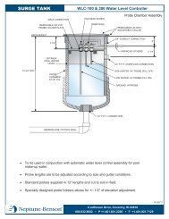
MODEL MFP 2 AUTOMATIC CONTROLLER
A. The controller shall govern the operation of the filter system by means of a programmable logic<br />
controller. All power to the controller and valves shall be 120 VAC or 230 VAC – single phase.<br />
B. The controller shall be housed in a Nema 4X fiberglass polyester enclosure with padlockable<br />
stainless steel snap latch hinges.<br />
C. The controller shall include a 4-row x 24 character LCD display with a 16 button numeric tactile<br />
feedback keypad and programmable function keys with LED's. The unit shall display system<br />
operation and status functions.<br />
D. The controller shall include (5) miniature plug-in double pole/double throw (DPDT) relays and (4)<br />
quick disconnect fuse holders fully integrated to manage the system functions.<br />
E. A pressure switch shall be installed to sense and signal for backwash actuation based on a preset<br />
pressure drop.<br />
F. ½" strain relief connections shall be provided in the bottom of the enclosure for all of the necessary<br />
input connections.<br />
G. The Model MFP 2 Controller shall provide the following operational features:<br />
1. Manual backwash initiation<br />
2. Automatic backwash initiation (pressure and/or time options)<br />
3. Timer for time clock backwashing<br />
4. Fixed backwash duration and delay features<br />
5. Real time clock with battery backup of data entry to maintain time during power failure.<br />
6. Capable of controlling up to (4) filters and (1) one priority valve<br />
H. All controller programming shall be accomplished using on-screen instructions.<br />
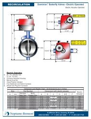
ELECTRIC OPERATORS<br />
A. Electric service shall be 110 VAC.<br />
B. Operator housing shall be corrosion resistant NEMA 4X (IP65).<br />
C. Electrical connectors shall be four-pole industrial style and meet DIN 43650 standards. Plug<br />
connection shall be gasketed and mechanically secured with a stainless steel screw. Harness<br />
assemblies from operator to control panel shall be factory fabricated. No field wiring shall be<br />
required.
D. Drive assembly shall include hardened steel and polyamide reduction gears with permanent<br />
lubrication.<br />
E. Operator shall be equipped with a manual override.<br />
F. Operator shall have a visual position indicator.<br />
G. Electric drive motor minimum duty cycle rating to be 35%. Overloading protection shall be selfresetting.<br />
H. Limit switches shall be provided to allow adjustment of cycle.<br />
I. Two additional limit switch contacts shall be provided for indication or auxiliary.<br />
PNEUMATIC OPERATORS<br />
A. The actuators shall be double acting with valve mounted drilling to ISO 5211.<br />
B. The actuators shall include (2) 1/4" FPT ports for open / close connections. Flow control valves with<br />
quick connect fittings shall be provided at each port to allow speed control adjustment for the open /<br />
close function of the actuators.<br />
C. Materials of Construction<br />
1. Body: aluminum alloy, extruded acc. to ASTM 6063, anodized acc. To UNI 4522<br />
2. Ends: Die-cast in aluminum alloy acc. To ASTM B179, epoxy-polyester coated<br />
3. Pistons: Die-cast in aluminum alloy acc. To ASTM B179<br />
4. Pinion: Nickel-plated steel<br />
5. Slideways: Acetal resin (LAT LUB 731320T)<br />
6. Fasteners: AISI 304 Stainless steel<br />
7. Springs: Epoxy coated steel, pre-compressed<br />
8. Seals: NBR Nitrile rubber<br />
9. Lubricant: MoS2<br />
D. The actuators shall be factory lubricated to allow for 1,000,000 maneuvers.<br />
E. The actuators shall have adjustable travel stops for both directions.<br />
F. Working temperature limits: 4ºF to 186ºF.<br />
H. A tool kit for adjustment of pneumatic actuators shall be provided by the filter manufacturer.
FILTER / REGULATOR<br />
A. Each filter shall include a combination filter / regulator. The regulator shall be adjustable from 0 –<br />
120 p.s.i. 1/2” F.P.T. connections shall be provided for field installation of air lines.<br />
WATER SEPARATOR<br />
A. One water separator with automatic drain shall be included for each air compressor supplied. 1/2”<br />
F.P.T. connections shall be provided for field installation of air lines.<br />
AIR COMPRESSOR<br />
A. The system will require (1) air compressor per mechanical room. The following is the minimum<br />
requirement: 30 gallon tank, 2 HP 120v, 1 phase, 15 amp, 5.5 CFM @ 90 psi, air pressure gauge,<br />
pressure relief valve, belt guard, pressure switch, air filter<br />
SOLENOID VALVES<br />
A. Each filter shall include the required number of single solenoid, 4-way valves mounted on a multistation<br />
manifold for operation of the pneumatic actuators.<br />
B. The solenoids valves shall include lighted DIN connectors.<br />
C. The solenoid valves shall be factory lubricated and shall not require any field lubrication.<br />
D. The solenoid valves with multi-station manifold shall be located on the gauge panel, factory wired<br />
and include quick connect fittings for attachment to the pneumatic actuators.<br />
E. The solenoid valves shall be SMC Series SY 7000.<br />
MEDIA<br />
A. Gravel support media of a hard coarse aggregate with a subangular grain shape with a particle size of<br />
1/8" x 1/4" shall be used on the inside of the bottom head to the elevation where the filter media<br />
commences. The specific gravity shall not be less than 2.5. Support media shall be placed by hand<br />
to avoid damage to the underdrain system and leveled before the addition of the upper layer of filter<br />
media. Concrete underfill is not recommended. Support gravel shall be delivered and stored in 100<br />
pound bags (approximately one cubic foot) for ease of handling and elimination of possible<br />
contamination. Media shall be free from minerals which may precipitate onto pool surfaces.<br />
B. Sand shall be a carefully selected grade of hard, uniformly graded silica material. Media shall be<br />
naturally rounded particles of silica or milled angularly shaped particles of silica quartz. Sand shall<br />
have a particle size between .45mm and .55 mm.(#20). No more than 1.5% shall be allowed to pass<br />
through a #40 sieve (.0164”). Uniformity coefficient shall not exceed 1.53. Specific gravity to be
not less than 2.5. Filter shall contain a minimum bed depth as shown on the drawings. Systems<br />
which do not provide a minimum bed depth as shown on the drawings will not be acceptable. Sand<br />
shall be delivered and stored in 100 pound bags (approximately one cubic foot) for ease of handling<br />
and elimination of possible contamination. Media shall be free from minerals which may precipitate<br />
onto pool surfaces.<br />
C. Each filter tank shall be provided with media quantities as shown on the drawings<br />
FILTER SYSTEM PACKAGING<br />
A. All filter piping and valves shall be factory assembled and knocked down into sub-assemblies for<br />
shipment.<br />
B. The components shall be carefully packaged in a totally enclosed wooden crate to prevent damage<br />
during transport.<br />
PART 4 – WARRANTIES<br />
FILTER<br />
A. Filter tanks shall carry a 10 year fully rated warranty as regularly offered by the tank manufacturer.<br />
B. Internal and external face piping shall carry a fully rated 3 year warranty.<br />
VALVES<br />
A. Valve bodies shall carry a 5 year fully rated warranty.<br />
B. Valve operators shall carry one (1) year warranty as provided by the product manufacturer.<br />
SYSTEM ACCESSORIES<br />
A. System accessories including sight glass, pressure gauges, pumps and air relief valve shall carry one<br />
(1) year warranty as provided by the product manufacturer.