Variable Frequency Drive Specifications Technical Data
Variable Frequency Drive Specifications Technical Data
Variable Frequency Drive Specifications Technical Data

Create successful ePaper yourself
Turn your PDF publications into a flip-book with our unique Google optimized e-Paper software.
VFD<br />
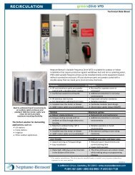
A. A <strong>Variable</strong> <strong>Frequency</strong> <strong>Drive</strong> (VFD) shall be provided for each filter pump motor.<br />
B. The <strong>Variable</strong> <strong>Frequency</strong> <strong>Drive</strong>s (VFDs) shall be solid state, with a Pulse Width Modulated (PWM)<br />
output. The VFD package as specified herein shall be enclosed in a NEMA 4 enclosure, completely<br />
assembled, programmed and tested by the manufacturer. The VFD shall employ a full wave rectifier<br />
(to prevent input line notching), capacitors, DC link inductors, and Insulated Gate Bipolar<br />
Transistors (IGBTs) as the output-switching device. The drive efficiency shall be 97% or better at<br />
full speed and full load. Displacement power factor shall be no less than 0.98 at all speeds and loads.<br />
C. All NBCFW VFDs shall be factory programmed per the unique requirements of each job per<br />
Neptune-Benson specifications. Programming shall include but shall not be limited to filter pump<br />
motor specifications, remote start/stop requirements, run confirm requirements and PID loop<br />
requirements.<br />
D. VFDs and options shall be UL and CUL listed as a complete assembly. VFDs and options shall be<br />
UL, CUL, and CE labeled as a component.<br />
E. Harmonic Distortion Control:<br />
The VFD design shall incorporate mechanisms that lower the harmonic currents caused by the drive<br />
as compared to standard six-pulse drives onto the AC power line. Harmonic calculations shall be<br />
supplied upon request based on a single line diagram of the electrical system. This diagram shall<br />
include transformer(s) KV, kVA and impedance percentage to accurately predict the harmonic levels<br />
at the PCC (Point of Common Coupling), as specified by IEEE519-1992. The calculations shall be<br />
made with the point of the common coupling being the utility feeder.<br />
F. <strong>Specifications</strong>:<br />
1. Input voltage 200-240, 380-480, 575-600 VAC +/- 10%, 3 phase, 48-63 Hz.<br />
2. Voltage tolerance + 10% or – 15% of specified line voltage.<br />
3. Output <strong>Frequency</strong> 0 to 300 Hz. Operation above 60 Hz shall require programming changes to<br />
prevent inadvertent high-speed operation.<br />
4. Environmental operating conditions: -10 to 50°C, 0 to 1000 meters above sea level, less than<br />
90% humidity, non-condensing.<br />
5. Enclosure shall be rated NEMA 4 or as specifically mentioned elsewhere.<br />
G. The VFD shall be wired into the RMF controller for on/off and run confirm functions. Wiring shall<br />
be by electrical contractor.<br />
H. The VFD shall be a WEG NBCFW series.<br />
I. The VFD shall be equipped with a bypass. Bypass option shall send the motor to bypass mode based<br />
on an easily accessible door-mounted selector or based on the drive’s programmable relay. A bypass<br />
pilot light shall provide indication of the bypass mode. The bypass mode shall provide overload<br />
protection. Contactors shall be electrically and mechanically interlocked. An essential services mode<br />
shall send the motor to bypass regardless of the selected mode.<br />
J. A disconnect switch, as may be required by local electrical codes, shall be provided by others.