User Manual IMPORTANT SAFETY INSTRUCTIONS
User Manual IMPORTANT SAFETY INSTRUCTIONS
User Manual IMPORTANT SAFETY INSTRUCTIONS

Create successful ePaper yourself
Turn your PDF publications into a flip-book with our unique Google optimized e-Paper software.
Four Post Parking Lift<br />
4QJY3.0-C<br />
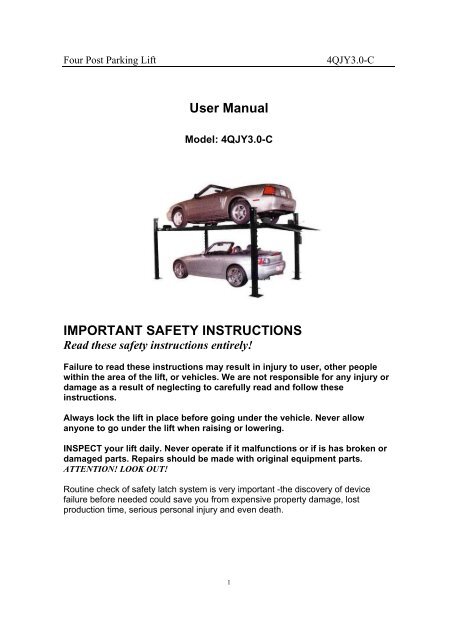
<strong>User</strong> <strong>Manual</strong><br />
Model: 4QJY3.0-C<br />
<strong>IMPORTANT</strong> <strong>SAFETY</strong> <strong>INSTRUCTIONS</strong><br />
Read these safety instructions entirely!<br />
Failure to read these instructions may result in injury to user, other people<br />
within the area of the lift, or vehicles. We are not responsible for any injury or<br />
damage as a result of neglecting to carefully read and follow these<br />
instructions.<br />
Always lock the lift in place before going under the vehicle. Never allow<br />
anyone to go under the lift when raising or lowering.<br />
INSPECT your lift daily. Never operate if it malfunctions or if is has broken or<br />
damaged parts. Repairs should be made with original equipment parts.<br />
ATTENTION! LOOK OUT!<br />
Routine check of safety latch system is very important -the discovery of device<br />
failure before needed could save you from expensive property damage, lost<br />
production time, serious personal injury and even death.<br />
1
Four Post Parking Lift<br />
4QJY3.0-C<br />
Operating controls are designed to close when released. Do not block open or<br />
override them.<br />
NEVER overload your lift. Manufacturer’s rated capacity is shown on<br />
nameplate affixed to the lift. ALWAYS know the gross weight of vehicle.<br />
NEVER use the lift to raise one end or one side of vehicle.<br />
NEVER raise vehicle with anyone inside it. No one should be in the lift area<br />
during operation.<br />
ALWAYS keep lift area free of obstructions, grease, oil, trash and other debris.<br />
Before lowering lift, be sure tool trays, stands, etc. are removed from under<br />
vehicle. Release locking devices before attempting to lower lift.<br />
Adequate ventilation should be provided when working on internal<br />
combustion engines.<br />
Use only manufacturer’s recommended attachments.<br />
KEEP HANDS AND FEET CLEAR. Remove hands and feet from any moving<br />
parts. Keep feet clear of lift when lowering. Avoid pinch points.<br />
GUARD AGAINST ELECTRIC SHOCK. This lift must be grounded while in<br />
use to protect the operator from electric shock. Never connect the green<br />
power cord wire to a live terminal. This is for ground only.<br />
DANGER! The power unit used on this lift contains high voltage.<br />
Disconnect power at the receptacle before performing any electrical<br />
repairs. Secure plug so that it cannot be accidentally plugged in during<br />
service.<br />
WARNING! RISK OF EXPLOSION. This equipment has internal arcing or<br />
sparking parts which should not be exposed to flammable vapors. This<br />
machine should not be located in a recessed area or below floor level.<br />
MAINTAIN WITH CARE. Keep lift clean for better and safe performance.<br />
Follow manual for proper lubrication and maintenance instructions. Keep<br />
control handles and/or buttons dry, clean and free from grease and oil.<br />
STAY ALERT. Watch what you are doing. Use common sense. Be aware.<br />
CHECK FOR DAMAGED PARTS. Check for alignment of moving parts,<br />
breakage of parts or any condition that may affect its operation. Do not use lift<br />
if any component is broken or damaged.<br />
2
Four Post Parking Lift<br />
4QJY3.0-C<br />
NEVER remove safety related components from the lift. Do not use lift if<br />
safety related components are damaged or missing.<br />
ALWAYS wear safety glasses. Every day eyeglasses only have impact<br />
resistant lenses. They are not safety glasses. READ AND UNDERSTAND ALL<br />
<strong>SAFETY</strong> WARNINGS & PROCEDURES BEFORE OPERATING LIFT. POST<br />
THESE <strong>SAFETY</strong> TIPS WHERE THEY WILL BE A CONSTANT REMINDER TO<br />
YOUR LIFT OPERATOR. FOR INFORMATION SPECIFIC TO THE LIFT, ALWAYS<br />
REFER TO THE LIFT MANUFACTURER’S MANUAL.<br />
Improper installation can cause accelerated<br />
wear, resulting in catastrophic failure which<br />
may cause property damage and / or bodily<br />
injury. Manufacturer will assume no liability for<br />
loss or damage of any kind, expressed or<br />
implied, resulting from improper installation or<br />
use of this product. Read this installation<br />
manual in its entirety before attempting to<br />
install or operate the lift.<br />
SELECTING SITE: Before installing your new lift, check the following.<br />
OVERHEAD OBSTRUCTIONS: The area where the lift will be located should be free<br />
of overhead obstructions such as heaters, building supports, electrical lines etc.<br />
FLOOR REQUIREMENTS: Visually inspect the site where the lift is to be installed and<br />
check for cracked or defective concrete. This lift must be installed on a solid level<br />
concrete floor with no more than 2 degrees of slope. A level floor is suggested for<br />
proper installation and level lifting. If a floor is of questionable slope, consider a survey<br />
of the site and/or the possibility of pouring a new level concrete slab. This lift is<br />
designed to be installed on a minimum of 180mm thick, 3500psi, steel reinforced<br />
concrete. Do not install this lift on asphalt, wood, or any other surface other than<br />
described. This lift is only as strong as the foundation on which it is installed.<br />
3
Four Post Parking Lift<br />
4QJY3.0-C<br />
DO NOT install this lift outdoors unless special consideration has been made to<br />
protect the power unit from weather conditions. The Power unit is not water<br />
proof!!!<br />
DO NOT begin installation with lift close to wall. It is necessary to leave adequate<br />
clearance for installing safety linkage rods. Allow 1524mm for clearance. (See Fig.1)<br />
NOTE The power unit can be placed in one of two locations, front left or rear right<br />
(See Fig. 1)<br />
Unpacking: Unpack the lift close to the installation site. Review your packing list and<br />
assembly drawing to verify that you have all the parts. Layout a chalk line on the floor<br />
following the floorplan (See Fig.1).<br />
Stand the columns in place making sure to position the power unit mounting<br />
bracket at the correct location and the lock blocks facing outward.<br />
TOOLS recommended<br />
"Rotary Hammer Drill Or Similar ( If Anchoring ) "Medium Crescent Wrench<br />
"φ19" Masonry Bit ( If Anchoring / Not required) "Medium Pipe Wrench<br />
"Hammer "Crow Bar "<br />
4 Foot Level "Chalk Line<br />
"Open-End Wrench Set: 12-28 "Medium Flat Screwdriver<br />
"Socket And Ratchet Set: 12 -28 "Tape Measure: 5m Minimum<br />
"Hex-Key / Allen Wrench Set "Needle Nose Pliers<br />
4
Four Post Parking Lift<br />
4QJY3.0-C<br />
COLUMN & CROSSRAIL INSTALLATION Lay down rear columns. Position the<br />
crossrail at the top of the two columns. (both cross rails are the same ) Install the<br />
crossrail in the column by sliding the plastic guide blocks into the column channel. The<br />
safety latch must be positioned with bevel side to the leg top, and safety latch facing<br />
towards the outside of the lift when you stand the columns back up. <strong>Manual</strong>ly open the<br />
safety latch devise on each side of the crossrail and slide the crossrail down until it<br />
rests on the safety lock position closest to the floor. Repeat the procedure for the<br />
remaining columns and crossrail. Stand the assembled columns up in the positions<br />
indicated on the floor plan.<br />
Track Installation<br />
Start with the track with the cylinder. This track will be located with the hose<br />
connection facing out toward the leg with power unit bracket attached. NOTE The<br />
power unit can be located in two locations shown. With an assistant, pick up and place<br />
one end of the main side track on the crossrail, and then pick up and place the other<br />
end on the opposite crossrail (if you have three assistants, place both ends at the<br />
same time). Use a large screwdriver or aligning punch to align the mounting holes in<br />
the cross rails with the mounting holes in the track. Do not leave the tracks unbolted<br />
– install the mounting bolts immediately! Install M12X100 mounting bolts and<br />
M12 washers thru the ramp brackets and wheel stops. Make sure the bolt head is on<br />
the flat side of the bracket. Install the two ramp brackets and two wheel stop with bolts<br />
and washers as you secure the main side track to the cross rail. Secure the bolts with<br />
M12 washers and nuts placed hand tight. Now, install the offside track and again<br />
secure with ramp brackets, wheel stops with M12X100 bolts and nuts. After both<br />
tracks are installed, tighten all bolts M12X100 bolts -torque -60 N-M.<br />
Find the leg caps (4 each), M12X170 bolts (4 each), M12X30 bolts (4 each), M12<br />
nuts (8 each) and M12 flat washers (16 each), holes for cable face towards the<br />
center of the lift. Secure the leg caps with M12X30 bolts. Place the bolts with washers<br />
in through channel and secure with washers and nuts on the outside of the leg. Install<br />
the M12X170 bolts through the leg and top cap. Install from outside of the leg, and<br />
secure with a nut on the inside of the leg. Tighten the M12X30 bolt. Tighten the<br />
M12X170 bolt to a torque of 60N-M. Do not over tighten the M12X170 bolt, as this<br />
may warp the column channel and bind the guide blocks.<br />
5
Four Post Parking Lift<br />
4QJY3.0-C<br />
Insert the bolt end of the cable through the opening in the offside track, then run<br />
cable ¼ turn or 90 degrees around the pulley on the crossrail. Secure the bolt end to<br />
the leg top cap. Place washer and nut on threaded end hand tight.<br />
Safety Latch Linkage Installation: Locate and identify the components needed to<br />
install the safety latch linkage rods. Install the spacers from on the straight threaded<br />
end of the M12X1270 bent rod and the threaded end of the M12X3200 straight<br />
safety latch linkage rod.<br />
Install the M12X1270 bent safety latch linkage rod into the main side track adjacent<br />
to back end of the cylinder (opposite the cylinder rod). Safety latch linkage rod should<br />
pass through guide tubes on underside of track.<br />
Install the M12X3200 straight safety latch linkage rod into the main side track from<br />
the opposite end. The rod should pass through two guides on the underside of the<br />
main side track.<br />
Install the 90 fitting w/O-Ring in the base of power unit pump next to the lever<br />
operated release valve. IT IS NOT NECESSARY TO USE TEFLON TAPE ON<br />
O-RING FITTINGS.<br />
Attach the 1800MM hose to the fitting on the power unit. Attach the other end of the<br />
1800MM hose to outside fitting in main side track.<br />
Place a funnel into vent cap hole and fill the tank with one of the following fluids:<br />
AW-32 or ISO-32 hydraulic oil. Mobile DTE 24, or Texaco HD 32 DO NOT USE<br />
DEXRON® IN THIS LIFT! This tank will hold approximately 10L<br />
Relocating or changing components may cause problems. Each component in the<br />
system must be compatible; an undersized or restricted line will cause a drop in<br />
pressure. All valve, pump, and hose connections should be sealed and/or capped until<br />
just before use. All parts should be supplied from manufacture. Air hoses can be used<br />
6
Four Post Parking Lift<br />
4QJY3.0-C<br />
to clean fittings and other components. However, the air supply must be filtered and<br />
dry to prevent contamination. Most important -cleanliness -contamination is the<br />
most frequent cause of malfunction or failure of hydraulic equipment.<br />
Check Pulley Cover and Lock Collars: Before proceeding, double check to make<br />
sure the locking shaft collars for the crossrail cable pulleys are tight and secure.<br />
Check the pulley cover (2-RIGHT and 2 LEFT) over the shaft located on the pulley<br />
side of each crossrail. CHECK the pulley and cover are firm against the locking shaft<br />
collar already in place. Check the additional lock collar on the outside of the shaft is<br />
tight and secure. To prevent personal injury or death, crossrail lock collars must be<br />
tight. If they are ever removed -always make sure the locking shaft collars are tight<br />
and secure.<br />
Check the crossrail locking assembly before use. Make sure all bolts and<br />
collars are tight. The assembly is pre-installed from the factory but parts may<br />
come loose during shipping.<br />
After installation is completed, before start up, be sure to inspect and<br />
tighten all bolts.<br />
Start Up: Make sure power unit reservoir is full with 10L of 10-wt hydraulic oil and<br />
spray the inside of the columns where the slide blocks glide with a light lubricant.<br />
Initial Operation: Press the UP SWITCH on the power unit. Raise the lift slowly until<br />
all the slack in the cables is taken out. Raise the lift until the safety latch closest to the<br />
power unit comes within 25MM to the bottom of the lowest lock position. Tighten the<br />
cable-adjusting nut on top of each leg cap until all remaining safety latches come<br />
within 25MM to the bottom of the lowest lock position. If cables are adjusted evenly the<br />
lift should be raising level and all four safety latches engage or audibly click<br />
simultaneously.<br />
IF LIFT DOES NOT RISE: Check hose connections. Fluid should be pumping<br />
through the hose. Check fluid level.<br />
NOTE: There will be some initial stretching of the cables in the beginning. It will be<br />
necessary to readjust the cables a week or so after first use.<br />
Run the lift up and down a few times to make sure that the safety latches is<br />
engaging uniformly and that the safety latch release is functioning properly.<br />
Re-adjust if necessary.<br />
When lowering the lift PAY CAREFUL ATTENTION. ALWAYS make sure that all<br />
FOUR <strong>SAFETY</strong> LATCHES are disengaged. If one of the latches locks on descent<br />
STOP immediately and raise until it is clear of the stop and adjust the hemin on that<br />
latch.<br />
Install the approach ramps on the entry side of the lift. Drive a vehicle onto the lift<br />
7
Four Post Parking Lift<br />
4QJY3.0-C<br />
tracks then install the rear wheel chocks. Run the lift up and down a few times to<br />
insure that the latches are engaging uniformly and that the safety latch release is<br />
functioning properly. Re-adjust if necessary.<br />
Run the lift up and down at least three times, before putting a vehicle on it for the first<br />
time. This is to bleed the air out of the cylinder and power unit.<br />
OPERATION Do not use this lift unless you know the proper operation of the lift<br />
and its safety devices, and the hazards involved. See Safety Instructions page 2<br />
and 3.<br />
1 Drive the vehicle onto lift platform. Set the vehicle’s parking brake and leave the<br />
transmission in park / gear. Chock the vehicle’s wheels.<br />
2 Stand clear -Push the top UP button to raise vehicle to desired height. Push the<br />
rod handle on the power unit to open release valve and lower tracks until it stops,<br />
check the all four latches for full engagement in the rack on each leg.<br />
3 To lower – push UP button to raise – rotate latch release rod handle and hold<br />
-push rod handle on power unit to lower. Warning: Make sure all four latches release –<br />
if not STOP, raise higher until latch is clear, if it does not work now the hemin -tie rod<br />
end on that latch needs adjustment.<br />
4 Any hydraulic oil leakage, unusual noise, or excessive wear must be fixed<br />
before using lift.<br />
PRE OPERATION CHECK The user should perform daily check. ATTENTION! LOOK OUT!<br />
Daily check of safety latch system is very important -the discovery of device failure before<br />
needed could save you from expensive property damage, lost production time, serious<br />
personal injury and even death.<br />
1 Check safety latches for free movement and full engagement with rack.<br />
2 Check hydraulic connections, and hoses for leakage.<br />
3 Check cables for damage and that they are in the groove on cable sheave.<br />
4 Check lock collars at all rollers and sheaves.<br />
5 Check bolts, nuts, and screws and tighten.<br />
6 Check wiring & switches for damage.<br />
7 Keep base plate free of dirt, grease or any other corrosive substances.<br />
8
Four Post Parking Lift<br />
4QJY3.0-C<br />
Fig 1<br />
9
Four Post Parking Lift<br />
4QJY3.0-C<br />
10
Four Post Parking Lift<br />
4QJY3.0-C<br />
11