Orbitrek Elite Instruction Manual - Thane
Orbitrek Elite Instruction Manual - Thane
Orbitrek Elite Instruction Manual - Thane

Create successful ePaper yourself
Turn your PDF publications into a flip-book with our unique Google optimized e-Paper software.
Owner’s <strong>Manual</strong><br />
Owner’s <strong>Manual</strong><br />
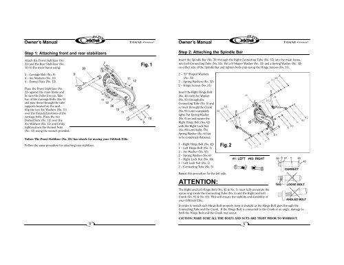
Step 1: Attaching front and rear stabilizers<br />
Step 2: Attaching the Spindle Bar<br />
Attach the Front Stabilizer (No.<br />
23) and the Rear Stabilizer (No.<br />
10) to the main frame using:<br />
23<br />
Fig. 1<br />
Insert the Spindle Bar (No. 38) through the Right Connecting Tube (No. 55) into the main frame,<br />
into Left Connecting Tube (No. 24). Put a D Shaper Washer (No. 33) and a Spring Washer (No. 32)<br />
on either side of the Spindle Bar and tighten both ends using the Hinge Screws (No. 31).<br />
4 – Carriage Bolt (No. 9)<br />
4 – Arc Washers (No. 11)<br />
4 – Domed Nuts (No. 12)<br />
Place the Front Stabilizer (No.<br />
23) against the main frame and<br />
be sure the holes line up. Take<br />
two of the Carriage Bolts (No. 9)<br />
and pass them through the tube<br />
supports located on the unit.<br />
Slip the two Arc Washers (No. 11)<br />
over the threaded portions of the<br />
carriage bolts. Place the two<br />
Domed Nuts (No. 12) over the<br />
Arc Washers (No. 11) and firmly<br />
tighten down the Domed Nuts<br />
(No. 12) using the wrench provided.<br />
Notice: The Front Stabilizer (No. 23) has wheels for moving your <strong>Orbitrek</strong> <strong>Elite</strong>.<br />
Follow the same procedure for attaching rear stabilizer.<br />
9<br />
11<br />
12<br />
36<br />
12<br />
11<br />
11<br />
12<br />
9<br />
10<br />
2 – “D” Shaped Washers<br />
(No. 33)<br />
2 – Spring Washers (No. 32)<br />
2 – Hinge Screws (No. 31)<br />
I n s e rt the Right Hinge Bolt<br />
(No. 42) with Arc Wa s h e r<br />
(No. 93) through the<br />
Connecting Tube (No. 5) and<br />
s c rew it through the Crank<br />
(No. 91) until completely<br />
tight. Put Spring Washer<br />
(No. 6) on and secure the<br />
Right Hinge Bolt (No. 42)<br />
with the Right Lock Nut<br />
(No. 89) until tight. The<br />
Spring Washer (No. 6) has<br />
to be completely flattened.<br />
1 – Right Hinge Bolt (No. 42)<br />
1 – Left Hinge Bolt (No. 1)<br />
2 – Arc Washer (No. 93)<br />
2 – Spring Washer (No. 6)<br />
1 – Right Lock Nut (No. 89)<br />
1 – Left Lock Nut (No. 7)<br />
2 – Connecting Tube (No. 5)<br />
Fig. 2<br />
Repeat this procedure for the left side.<br />
#1: LEFT #42: RIGHT<br />
89 6 91 5 93<br />
CORRECT<br />
42<br />
ATTENTION:<br />
Gap<br />
LOOSE BOLT<br />
The Right and Left Hinge Bolt (No. 42 & No. 1) must fully penetrate the<br />
nylon ring inside the Connecting Tube (No. 5) and the Right and Left<br />
Crank (No. 91 & No. 83). This will ensure the stability and durability of<br />
your <strong>Orbitrek</strong> <strong>Elite</strong>.<br />
ANGLED BOLT<br />
In order to install each Hinge Bolt properly, keep it straight as the Hinge Bolt goes through the<br />
Connecting Tube and the Crank. If the Hinge Bolt is connected to the Crank at an angle, damage to<br />
both the Hinge Bolt and the Crank may occur.<br />
CAUTION: MAKE SURE ALL THE BOLTS AND NUTS ARE TIGHT PRIOR TO WORKOUT.<br />
4<br />
5