
You also want an ePaper? Increase the reach of your titles
YUMPU automatically turns print PDFs into web optimized ePapers that Google loves.
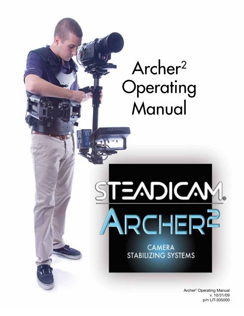
<strong>Archer</strong> 2<br />
Operating<br />
<strong>Manual</strong><br />
<strong>Archer</strong> 2 Operating <strong>Manual</strong><br />
v. 10/31/09<br />
p/n LIT-305000
STEADICAM ARCHER 2<br />
Copyright The <strong>Tiffen</strong> Company 2009<br />
All rights reserved.
Table of Contents<br />
Overview 5<br />
The <strong>Archer</strong> 2 Sled 6 – 7<br />
The Stage 8 – 9<br />
The Tilt Head<br />
10 –11 <br />
Smart Motorized Stage<br />
12 –15 <br />
Monitors 16<br />
The G-40 Arm 17<br />
The LX Vest 18 – 19<br />
Sled Base Connections 20<br />
Posts and clamps 21<br />
Attaching the Camera 22 – 23<br />
Static Balancing 24 – 25<br />
Dynamic Balancing 26 – 27<br />
Arm Adjustments 28 – 29<br />
Getting Started 30<br />
Goofy Foot 31<br />
Low Mode 32 – 33<br />
Maintenance 34<br />
Supplied Accessories, Cases and Packing 35<br />
This manual is primarily written to inform experienced Steadicam operators about specific features of the<br />
<strong>Archer</strong> 2 system. While there is some basic information in this manual to get a novice started, we strongly<br />
urge anyone with limited Steadicam experience to take one of our three or six day workshops. For more<br />
information on professional workshops worldwide, contact The <strong>Tiffen</strong> Company at www.tiffen.com or<br />
www.steadicam.com<br />
STEADICAM, G-40, <strong>Archer</strong> 2, UltraBrite, are registered trademarks of The <strong>Tiffen</strong> Company.<br />
<strong>Archer</strong> 2 Operating <strong>Manual</strong> p/n LIT-305000 v. 10/31/09
<strong>Archer</strong> 2<br />
Overview<br />
4
Overview<br />
The <strong>Tiffen</strong> Company takes great pride in producing the Steadicam ® <strong>Archer</strong> 2 . We are committed to excellence, innovation and<br />
service, and the <strong>Archer</strong> 2 is a system that will evolve with you. Each component of the <strong>Archer</strong> 2 is carefully designed so the operator<br />
can easily configure the Steadicam to the best possible advantage for each shot.<br />
Tool free — Our guarantee that all the advanced features can be used under real-world, fast-paced conditions.<br />
Modular design — We designed the <strong>Archer</strong> 2 to be easily modified, upgraded, maintained, and serviced.<br />
The optional, position-sensing, super strong, motorized stage increases the precision and repeatability of every shot.<br />
Stage positioning is smooth and effortless, and operators can trim the sled’s balance while shooting. “Go-to” buttons on the remote<br />
rebalance the sled to pre-determine positions — and return “home” — with just one touch.<br />
The integral tilt head tilts +/– 15º to preserve dynamic balance, to maintain high or low lens height, to help with clearance,<br />
reach, or viewing problems, or to execute precise whip pans with the lens angled up or down.<br />
The new, Wide Dovetail Lock has a broader, more positive grip on the dovetail plate. The handle has a safety stop to prevent<br />
accidental release.<br />
The <strong>Archer</strong> 2 gimbal has been meticulously engineered to provide a smooth precise feel incorporating high precision bearings<br />
and a quick release ergonomically recessed clamp mechanism for fast adjustments.<br />
Two section, carbon fiber telescoping post extends the sled from 23 to 34 inches (58-86cm) — or anywhere in between —<br />
for short to long mode shooting.<br />
The swept-back monitor mount is designed for maximum stiffness, inertial control and viewing options. It has a wider range<br />
of positions, both vertically and horizontally and is uniquely designed to safely fold up for transport or storage.<br />
The <strong>Archer</strong> 2 standard 7 inch LCD monitor is state of the art. It’s a daylight viewable (700 nits)16x9 composite monitor,<br />
with a frame line generator. The optional HDSDI (and composite) monitor is 7”, 16x9, and 400 nits. The optional UltraBrite 2 <br />
monitor is 8.4” at an astonishing 1400 nits brightness, with advanced AR coating, and HDSDI, HD component, and analog<br />
composite direct input. Its unique design lets it run cool without a fan.<br />
The connector rich sled design incorporates 3x HD quality video feeds from the top stage to sled base to accommodate<br />
RGB or any other video configuration. Main BNC composite video input, 3x 12/24V power connectors, 12V/Video connector<br />
for transmitters, monitor connector and tally connector are some of the other available connectors on the sled.<br />
Structural Dovetail Base — solidly mount gyros, extra batteries, balance weights or other accessories.<br />
Steadicam PowerCube dual battery pack provides 220 watt hours and high amperage discharge — plenty of power for<br />
the sled and today’s power hungry 35mm and High Def video cameras. The <strong>Archer</strong> 2 is a 12 and 24V volt system that uses either a<br />
single or dual PowerCube or Anton Bauer ® batteries. The new tilting battery mount creates more options for balancing and inertial<br />
control and also uniquely folds up for compact storage or transport.<br />
The LX vest is lightweight and ergonomic, working perfectly with the new generation of G-series arms.<br />
The G–40 arm is amazing, lifting from 12 to 40 pounds (5.4 to 18.1kg). This next generation of the G-Series arms provides<br />
a smooth Iso-elastic ride and incorporates a unique quick link mechanism to separate the arm sections for compact storage or<br />
transport. With an astounding boom range of 29 inches (74cm), and interchangeable arm post with rotational drag control,<br />
the G-40 arm gets the job done.<br />
All the features are integral to the design; ready to be used when you need them.<br />
The <strong>Archer</strong> 2 continues our tradition of building the world’s most versatile and user-friendly Steadicams.<br />
5
<strong>Archer</strong> 2<br />
The <strong>Archer</strong> 2<br />
Sled<br />
Fore - aft<br />
adjustment knob<br />
Dovetail locking<br />
mechanism<br />
Optional fore/aft stage motor<br />
Tally sensor level adjustment<br />
Frequency select<br />
switch for optional<br />
motorized stage<br />
Docking mount<br />
Upper R and B<br />
video connectors<br />
Upper post<br />
Gimbal<br />
Optional Gimbal<br />
remote<br />
Gimbal<br />
Handle<br />
LCD Monitor<br />
Tilting battery mount<br />
Post<br />
Clamp<br />
Monitor rod<br />
clamping<br />
mechanism<br />
Monitor Yoke<br />
6<br />
Battery release<br />
Battery rod<br />
clamping mechanism<br />
Sled base
Detail: mounting stage<br />
Dovetail locking<br />
mechanism<br />
Dovetail bracket<br />
Tilt head release levers<br />
Lower R and B<br />
video<br />
connectors<br />
Stage power and<br />
video connectors<br />
Video Out/12V<br />
Video in<br />
Monitor<br />
connector<br />
HDSDI BNC<br />
14V and 28V<br />
Accy Power<br />
Connector<br />
14V and 28V<br />
Camera Power<br />
HDSDI BNC<br />
Detail: folding sled<br />
Battery Unfold/Fold<br />
Procedure:<br />
• While holding the battery mount, rotate<br />
the blue locking knob for the battery<br />
counterclockwise (opposite direction to<br />
“LOCK” marking) until the stop.<br />
• Rotate the battery mount down and slide<br />
the rail tubes into the guide holes in the<br />
sled base.<br />
• Rotate the blue locking knob clockwise<br />
(same direction as “LOCK”marking) to<br />
secure the tubes in the desired operating<br />
position.<br />
• The folding procedure for the battery is similar<br />
to the unfold procedure taking note that the rail<br />
tubes should be flush with the sled base when<br />
folded for ease of packing.<br />
Monitor Unfold/Fold Procedure:<br />
• The monitor fold/unfold procedure is similar to<br />
that of the battery unfold/fold procedure taking<br />
note that the monitor mounting bracket on the<br />
post should be lowered all the way down to base<br />
for ease of packing.<br />
• Loosen the lobed knob below the battery<br />
mount and rotate the battery to the desired<br />
operating position; retighten the knob.<br />
7
<strong>Archer</strong> 2<br />
The Stage<br />
Stage mechanics and adjustments<br />
The dovetail clamp lever has<br />
three positions: forward and<br />
locked, 90º for adjustments,<br />
and 60º back for mounting<br />
or removing the dovetail<br />
plate. A safety button must<br />
be pushed to move the lever<br />
to the unlocked position; the<br />
same button holds the lever<br />
fully open, making flips to<br />
low mode and back a bit<br />
easier. Do not force the lever<br />
backwards beyond its stop.<br />
The stage connectors<br />
At the rear of the stage, left to right (port<br />
side to starboard side):<br />
• Camera power connector. 3 pin Lemo,<br />
+28V, +14V, and ground.<br />
• Video out/regulated 12V Power.<br />
4 pin Hirose<br />
• HDSDI video in BNC<br />
• Composite video in base of sled. BNC<br />
The stage is easy to adjust. The knob at the right<br />
rear controls fore and aft, and the two knobs on<br />
the side control side to side movement.<br />
Fore and aft<br />
adjustment knob<br />
Side to side<br />
adjustment knob<br />
Under the stage where the post meets the<br />
tilt head:<br />
• Two SMB connectors for two of the three<br />
RGB lines<br />
At the front (nosebox), left to right:<br />
• Power for focus motor receiver/amplifiers.<br />
3 pin Lemo (+28V, +14V, and ground)<br />
• Tally light connector (additional functions<br />
possible)<br />
Nosebox starboard side:<br />
• Pot to adjust Tally sensor sensitivity<br />
Note: The <strong>Archer</strong> 2 can be ordered<br />
without a motorized stage, or<br />
with a single motor, or with two<br />
motors. Upgrading to one or two<br />
motors is a simple “plug-and-play”<br />
operation.<br />
8
• Rotary switch to set remote<br />
channel (0-8)<br />
Starboard side of<br />
non-motorized<br />
stage shown<br />
Nosebox port side:<br />
• Power and mode LEDs<br />
• Side/Side motor controls<br />
• Fore/Aft motor controls<br />
• Stage centering<br />
The <strong>Archer</strong> 2 ’s optional motorized stage<br />
is position sensing – much like a focus<br />
motor system for a lens. One use of this<br />
feature is to set the stage to the center of<br />
travel, both fore and aft and side to side –<br />
great for initial setups.<br />
Pushing the double pole momentary<br />
switch on the “nosebox” to the “C” side<br />
centers the stage.<br />
Flipping the switch the other way (“L”)<br />
sets the stage to a pre-programmed<br />
position (more about that later.)<br />
stage motors to move. Remember this<br />
“function” when a stage motor stops<br />
working between takes!<br />
The electronics in the stage and nosebox<br />
are on “plug and play” circuit boards,<br />
easy to replace if there’s ever a problem.<br />
It’s also easy to access to the inside<br />
of the stage — to clean, add or swap<br />
motors, adjust the bearings, take apart for<br />
servicing, etc.<br />
Port side of<br />
non-motorized<br />
stage shown<br />
The speed and direction of the motors<br />
is set by the switches and thumbwheel<br />
pots on the left (port) side of the nosebox<br />
(S/S & F/A). Note that the motor<br />
direction switches also have a center-off<br />
position, just in case you are in an odd<br />
RF environment or you don’t want your<br />
9
<strong>Archer</strong> 2<br />
The Tilt Head<br />
The Tilt Head<br />
The integral, low profile head is designed to<br />
alter the lens angle +/-15º from horizontal<br />
with only a minor shift of the camera’s c.g.<br />
The most important use of the tilt head is in<br />
normal operating. Instead of trimming even<br />
two or three degrees for a shot by altering the<br />
<strong>Archer</strong> 2 ’s balance, use the tilt head to preserve<br />
a perfectly vertical post and keep your sled in<br />
dynamic balance.<br />
Trim for headroom<br />
Without the tilt head, much of the benefit of getting the sled into dynamic balance is wasted<br />
when one alters the trim of the rig. For example, operators routinely trim their sleds for<br />
headroom. This action puts the rig out of both static and dynamic balance.<br />
With the <strong>Archer</strong> 2 , the operator determines<br />
the proper length of sled, optimal monitor<br />
viewing position, inertia, and lens height.<br />
Then the operator adjusts the camera to<br />
the nominal tilt angle for the shot.<br />
10
Setting the tilt<br />
The operator sets the tilt by releasing the two clamps and manually repositioning the<br />
camera to the proper angle.<br />
The post remains vertical and the rig stays in (or close to) dynamic balance. Only<br />
minor static rebalancing is normally required, but exactly how much depends on the<br />
camera, accessories, sled length, monitor position, etc. In all cases, bringing the sled<br />
back into static balance by moving the camera will return the sled to dynamic balance<br />
as well (see page 28).<br />
The Tilt Head — General<br />
Operating<br />
Even if the Steadicam is slightly out of<br />
perfect dynamic balance, it’s a whole lot<br />
easier to hold the post vertical than at<br />
any other angle, especially when panning<br />
and accelerating - which we tend to do<br />
a lot when operating a Steadicam. The<br />
tilt head keeps the post vertical in many<br />
situations, making it easier to operate and<br />
keep things level.<br />
Long mode pans with the lens looking<br />
down - say at a crowd - used to be<br />
exceedingly difficult or impossible, due<br />
to the large spatial translations of the<br />
battery, monitor, and camera. But the tilt<br />
head leaves the post vertical and therefore<br />
eliminates this spatial translation, and<br />
makes these pans routine.<br />
Low mode and very low mode pans are<br />
also much easier and more precise.<br />
Another benefit of the tilt head: a whole<br />
new class of whip pans is now possible.<br />
All whip pans are done in dynamic<br />
balance with the post vertical. Previously<br />
this meant that the lens was always<br />
horizontal. With the tilt head, the lens can<br />
be angled up or down as much as fifteen<br />
degrees and the operator can still make<br />
extremely precise fast pans. Using the<br />
tilt head will increase the precision of any<br />
pan with a lens angled up or down – fast<br />
or slow.<br />
11
<strong>Archer</strong> 2<br />
Smart<br />
Motorized<br />
Stage<br />
The motorized stage is important for precise operating<br />
For precise work, the Steadicam must be carefully<br />
balanced or trimmed.<br />
Before operators had a motorized stage, all balancing<br />
had to be done before the shot and therefore the<br />
Steadicam’s balance was fixed throughout the shot.<br />
As well as that works, it was, as Garrett Brown has<br />
often said, “a situation akin to that of an airplane pilot<br />
landing his plane to adjust the flaps.”<br />
With the <strong>Archer</strong> 2 s motorized stage, the operator can<br />
continuously adjust the sled’s balance during the shot —<br />
assuring the utmost precision for every moment.<br />
When you push a button to change the Steadicam’s<br />
balance, you maintain your posture, stance, and grip,<br />
so even conventional, pre-shot balancing is quicker<br />
and more accurate.<br />
Some situations where the motorized<br />
stage really helps:<br />
• Anytime you want to trim precisely and quickly,<br />
whether trimming on the fly, in the middle of a shot,<br />
or holding an opening frame perfectly still.<br />
• In long mode (and sometimes in standard low<br />
mode), it is often difficult or impossible for the<br />
operator to reach the stage to manually adjust<br />
the sled’s balance.<br />
• While shooting from a vehicle, it can be awkward<br />
or even dangerous to balance the <strong>Archer</strong> 2 without<br />
the remote control.<br />
12
“Go-to” Buttons and the Smart<br />
Motorized Stage<br />
On the remote control, there are three “go-to”<br />
buttons on one side in addition to the four original<br />
“trim” buttons (as well as two other “spare” buttons).<br />
Programming is a snap; it’s just like programming<br />
stations on a car radio. Move the stage to the desired<br />
position, either manually or using the traditional trim<br />
buttons. Then hold one of the go-to buttons down for<br />
three seconds. The green LED will flash twice, and<br />
it’s set. You can even program any button on the fly,<br />
during the shot, if you have the mental reserves...<br />
Each go-to button simultaneously programs the fore<br />
and aft and the side to side position of the stage.<br />
Trimming fore and aft may slightly alter your side to<br />
side balance, or you may want to program in a severe<br />
Dutch angle. You can even program two or three<br />
buttons for the same trim if you like, so you don’t have<br />
to think about which button to push!<br />
The positions are stored in non-volatile memory, so<br />
changing batteries or turning off the sled power does<br />
not erase your presets.<br />
The go-to buttons move the stage to specific marks,<br />
defined by the operator. One position is usually the<br />
nominal balance, and the other two are programmed<br />
for some other part of the shot. During the shot,<br />
the operator (or an assistant holding the removable<br />
remote) pushes and quickly releases a go-to button<br />
to move the stage precisely to a new trim setting.<br />
Pushing the “home” button at any time returns<br />
the stage to the nominal trim. No more counting<br />
revolutions or so many seconds; the stage moves<br />
exactly where you want it to — and back.<br />
In addition to big tilts and Dutch angles, you might<br />
set a button to “post perfectly vertical and in dynamic<br />
balance,” and use another button for the nominal<br />
trim for the shot at hand. Or set the three buttons to<br />
roughly account for the side to side movement of film<br />
in some magazines.<br />
The center go-to button on remote shares the same<br />
preset as the “L” position on the switch on the nose<br />
box. The “L” position is programmed exactly like<br />
the center go-to button on the remote, and the red<br />
mode LED on the nosebox will flash to confirm<br />
programming.<br />
The “C” button can be programmed the same way as<br />
the “L” button. It might be useful to reprogram the<br />
“center” position if you were working with a camera<br />
and the nominal balance was shifted significantly side<br />
to side. Then every time you changed lenses or started<br />
the day you would not have far to go to rebalance side<br />
to side.<br />
Holding one of the go-to buttons down for more than<br />
six seconds will clear all programming for that button<br />
and make it non-operational. The green LED will flash<br />
3 times. It’s a good idea to clear out all 3 buttons at the<br />
beginning of the day.<br />
13
<strong>Archer</strong> 2<br />
Smart<br />
Motorized<br />
Stage<br />
Charging the remote<br />
If the transmitter’s battery is low, the<br />
LED will blink continuously after any<br />
button is depressed. To charge the remote,<br />
remove it from the gimbal handle. Plug<br />
the supplied cable into the remote and<br />
the other end into either one of the 4-pin<br />
HRS connectors on the sled.<br />
Changing the frequency<br />
To avoid interference with other systems,<br />
1 of 8 channels can be selected via the<br />
rotary switch on starboard side of nose<br />
box.<br />
Leave the sled on as you charge the<br />
battery. It takes about 5 hours to charge<br />
a completely discharged remote battery.<br />
When the battery is charging, the green<br />
LED will be on. When the lithium-ion<br />
battery is fully charged, the green light<br />
goes off.<br />
If plugging in a fully charged transmitter,<br />
the LED will remain lit for approximately<br />
ten minutes until the charge circuit<br />
determines the battery is actually full.<br />
Battery life can vary depending on how<br />
often the transmitter is used and the<br />
storage and operating conditions.<br />
The remote and the receiver must be<br />
on the same channel. Simultaneously<br />
holding down the top 2 go-to buttons<br />
for 6 seconds will enter the remote into<br />
a channel change mode. The number of<br />
LED blinks will correspond to channel<br />
selected.<br />
Change channels by pressing the fore or<br />
aft remote buttons (channel up or down).<br />
After the proper channel is selected, the<br />
programming mode will time out after 9<br />
seconds and re-flash the selected channel<br />
number. Channel 0 corresponds to 8<br />
flashes.<br />
(For operation outside of the USA) To<br />
select between US and UK frequency<br />
operation, there are two jumpers that<br />
must be changed. One jumper is inside<br />
the nosebox, the other is inside the<br />
remote. They must match for the system<br />
to work. The jumpers are set at the<br />
factory at the time of shipping. (902 –<br />
928MHz US and 868 to 870MHz UK)<br />
The green “PWR” LED on nose box<br />
comes on when the CPU is operational.<br />
14
<strong>Archer</strong> 2<br />
Monitors<br />
Monitors<br />
For information regarding your monitor, refer to<br />
the manufacturer’s manual.<br />
Color LCD monitor (standard)<br />
700 nits<br />
Built in frameline generator<br />
HD/SDI color 7” (optional)<br />
400 nits<br />
Fixed frame points standard.<br />
HD UltraBrite LCD monitor<br />
(optional)<br />
1400 nits<br />
Built-in frameline generator<br />
16
The G-40 Arm<br />
Arm post<br />
Forearm section<br />
<strong>Archer</strong> 2<br />
The G-40 Arm<br />
LIFT adjustment knob<br />
Titanium<br />
springs<br />
Upper arm section<br />
LIFT adjustment knob<br />
Double action<br />
hinge<br />
Quick release pin<br />
Titanium<br />
springs<br />
Socket<br />
LIFT adjustment knob<br />
Use the flat tool if there is any<br />
play in the vertical adjustment<br />
of the arm.<br />
RIDE adjustment knob<br />
shown for G-50 Series Arm<br />
available with S and SE<br />
<strong>Archer</strong> 2 models<br />
17
<strong>Archer</strong> 2<br />
The LX Vest<br />
Shoulder pads<br />
The LX Vest<br />
Chest pads<br />
Shoulder<br />
connector<br />
Socket<br />
block<br />
Hip pads<br />
Chest<br />
straps<br />
Adjustable<br />
buckles<br />
Hip<br />
straps<br />
Adjustable spar<br />
release and pin<br />
Socket block height<br />
adjustment<br />
Adjustable<br />
hook and loop<br />
straps<br />
Lower back pad<br />
18<br />
Optional Ultra Vest available
Fitting the Vest<br />
The vest is the major connection<br />
between your body and the Steadicam.<br />
It must be adjusted properly and feel<br />
good on your body. The vest is not<br />
intended to be a straightjacket. You<br />
should be able to move and breathe<br />
easily.<br />
The socket block for the arm should<br />
move with you and not shift under load.<br />
The overall length should be adjusted so<br />
that lifting your legs while taking a step<br />
up doesn’t disturb the vest. The hip pads<br />
should comfortably grab your hips.<br />
Start at the top<br />
• Be sure the shoulder pads are<br />
firmly down on your shoulders.<br />
• The chest pads are snugged<br />
up next. You should be able to<br />
breathe a little, but the vest should<br />
not be able to slip forward and<br />
down. Diaphragmatic breathing<br />
(like a baby) works best.<br />
• Push the vest down on your<br />
shoulders again, be sure the spar<br />
is vertical, then snug up the hip<br />
pads. If the hip pads are tightened<br />
first, the vest will tend to ride high<br />
until loaded, and then it will slip<br />
around under load.<br />
Note: A few operators have<br />
body shapes or sizes that<br />
are out of the general range<br />
of adjustments. You may find<br />
you have to add or remove<br />
padding, shorten or extend<br />
straps, etc. to make the vest fit<br />
perfectly.<br />
• Closing the clips on the hip and<br />
chest straps is the final step.<br />
Available options: a compact<br />
vest, and longer chest, hip,<br />
and cross back straps.<br />
Tip: While wearing<br />
the vest and resting<br />
between takes, release<br />
the vest straps to<br />
increase blood flow and<br />
ease tension in your<br />
muscles.<br />
• Pay close attention to the good fit<br />
of the vest in the photo (left). It’s<br />
very important how the shoulder<br />
pads contact the shoulders and<br />
the shoulder connectors are not<br />
too high (a common mistake).<br />
19
<strong>Archer</strong> 2<br />
Sled Base<br />
Connections<br />
20
Posts and clamps<br />
To balance heavy cameras, and/or to raise the lens<br />
height, make the rig longer. The telescoping post is<br />
adjusted by releasing the black wing clamp at the<br />
base of the post. Be sure to support the sled before<br />
you release the clamp.<br />
<strong>Archer</strong> 2<br />
Posts & Clamps<br />
Note: There is a safety line inside the posts to keep them<br />
from separating. The safety cable will prevent you from<br />
extending the post too far. Do not twist the bottom section<br />
more than 180 degrees from the top section as this will<br />
also twist the internal cables.<br />
Rotating Battery Mount<br />
The battery mount pivots approximately 270º to facilitate static balance, dynamic balance, storage,<br />
and for inertial control. Pivoting the battery all the way down will enable it to get closer to the sled,<br />
reducing pan inertia and/or helping to balance very heavy cameras. Pan inertia is maximized with<br />
the batteries horizontal and the battery rods fully extended.<br />
21
<strong>Archer</strong> 2<br />
Attaching the Camera<br />
Attaching the<br />
Camera<br />
Camera c.g. .75” (19mm)<br />
behind center post – fore-aft.<br />
Camera c.g. centered<br />
over post – side to side.<br />
The basic idea: We want to position the camera’s center of gravity about .75 inch (19mm) behind<br />
the centerline of the post fore-aft (as seen from the side) and directly over the centerline of the post<br />
side to side (as seen from the front or rear). We do this to facilitate both static and dynamic balancing.<br />
We fine-tune the placement of the camera as we balance the rig. See page 26.<br />
First, center the side to side and fore-aft adjustments of the camera mounting platform, using the knobs,<br />
the remote control, or better yet, flip the centering switch to “C” and the motorized stage centers itself!<br />
Attach all the accessories to the camera, including lenses, loaded film magazines, focus motors,<br />
obie lights, transmitters, etc. Don’t worry too much if you must add your motors or other accessories<br />
after you have attached the dovetail plate.<br />
Using a rod or pencil, find the c.g. of the camera, both fore-aft and side to side. Temporarily mark this<br />
with pieces of tape.<br />
Finding the camera’s fore-aft<br />
center of gravity.<br />
Finding the camera’s side to<br />
side center of gravity.<br />
22
Attach the long dovetail plate to the<br />
bottom of the camera, centered as closely<br />
as possible under the camera’s c.g.<br />
Use two screws to keep the plate from<br />
rotating.<br />
If possible, attach a second optional<br />
dovetail plate to the top of the camera,<br />
directly above the other dovetail. This<br />
may require additional hardware, such<br />
as a special low mode bracket for your<br />
camera.<br />
Dovetail locking lever fully open.<br />
If the camera won’t drop fully into place,<br />
be sure the left side of the dovetail is<br />
fully inserted, all is parallel, and the<br />
locking lever is fully open. It’s a close fit.<br />
After the dovetail drops into place, close<br />
the locking lever half way and slide<br />
the camera until the fore-aft c.g. mark<br />
is about .75 inches (19mm) behind the<br />
centerline of the telescoping posts.<br />
Push the locking lever forward to fully<br />
lock the camera into place. You are now<br />
ready to static balance the sled.<br />
Closing the locking lever.<br />
Push firmly.<br />
The dovetail locking lever has<br />
three positions (see page 8):<br />
• 60º back is fully open and the<br />
dovetail plate can be inserted or<br />
released.<br />
• At the half way or 90 degree<br />
position, the dovetail can<br />
slide back and forth for gross<br />
positioning of the camera. With the<br />
locking lever in this position, the<br />
dovetail can slide but cannot be<br />
removed.<br />
• All the way forward is the locked<br />
position.<br />
Place the camera above the camera<br />
mounting platform. Be sure the locking<br />
lever is fully open. Angle the left edge<br />
of the dovetail into the holder. Be sure to<br />
keep everything parallel. Lower the right<br />
side into the holder.<br />
Tip: If you add your focus motors at this point, remark the<br />
camera c.g. If the side-to-side position drastically changes,<br />
you may have to reposition the dovetail plate on the<br />
camera.<br />
Big, important tip: Wrap up, Tie up, Tie down, Hook and<br />
Loop, or Gaffer tape all cables so they don’t flop around<br />
and mess up your precise balancing. If you have cables<br />
that run to the outside world, leave them off at this point.<br />
23
<strong>Archer</strong> 2<br />
Static<br />
Balancing<br />
Static Balancing<br />
The Steadicam sled should be carefully balanced to help the operator<br />
get the shot.<br />
Before balancing, the sled should have the camera and battery<br />
attached, all cables secured, and all accessories on board. Place<br />
the camera c.g. about .75 inch (19mm) behind the centerline of the<br />
telescoping posts.<br />
Release the rod clamp<br />
at the base of the<br />
sled and pull out the<br />
battery three or four<br />
inches. Retighten the<br />
battery rod clamps.<br />
The camera mounting stage, monitor and battery<br />
should all be properly aligned.<br />
Release the proper clamp and rotate any section<br />
that is out of alignment.<br />
Mount the gimbal on the balancing stud. It’s a<br />
good idea at this point to have an assistant hold<br />
the C-stand. You need to balance the sled in<br />
all three axes: fore-aft, side to side, and top to<br />
bottom.<br />
Pick the most out of balance axis and get that<br />
close to being in balance, then work on another<br />
axis. You may have to go back to tweak the<br />
balance in any given axis several times.<br />
When the sled is very bottom heavy, it has<br />
a short drop time and it will require bigger<br />
movements of a weight to properly balance the<br />
sled.<br />
24<br />
When the sled is nearly neutrally balanced top to<br />
bottom, very slight movements of the camera or<br />
battery will have a large effect on balance. The<br />
sled will behave differently depending on how<br />
bottom heavy it is.
Adjusting top to bottom balance<br />
To adjust top-to-bottom balance, tilt the sled until<br />
it is horizontal. Hold the sled firmly and release<br />
the gimbal clamp.<br />
Slide the gimbal until the sled balances<br />
horizontally - but never allow the sled to move<br />
from horizontal with the gimbal clamp open.<br />
Slide the gimbal up towards the camera about .5<br />
inch (13mm) and lock the gimbal.<br />
Checking drop time<br />
Let the sled rotate (drop) through vertical and<br />
note the time. A two second drop time is a good<br />
starting point. Raise or lower the gimbal slightly<br />
to get a faster or slower drop time.<br />
Side-to-side and fore/aft balance<br />
Keep the camera c.g. about .75 inches (19mm)<br />
behind the centerpost and move the battery in<br />
or out to get close to fore-aft balance. Fine tune<br />
fore-aft balance with the knobs on the stage.<br />
Hold the sled absolutely vertical as you adjust<br />
the side-to-side or fore/aft balance. Turn the<br />
adjustment knobs with your other hand (or use<br />
the stage motor transmitter) until you feel no<br />
pressure on your operating hand, and the sled<br />
will be in static balance.<br />
To adjust the side-to-side balance, use the knobs<br />
on the camera mounting stage.<br />
A Really Fast Balancing Tip:<br />
To speed up the process of side-to-side<br />
and fore-aft balancing, stand next to the<br />
sled as you would while operating. Hold<br />
the sled vertical with your operating hand<br />
on the gimbal. Hold the gimbal the same<br />
way you would do while operating.<br />
Tip: When adjusting the balance fore-aft or sideto-side,<br />
moving any weight “up hill” makes the<br />
sled hang more vertically.<br />
25
<strong>Archer</strong> 2<br />
Dynamic<br />
Balancing<br />
Dynamic Balancing<br />
A Steadicam sled is in dynamic balance when the center post remains vertical as the sled is panned.<br />
Dynamic balance is extremely important for precise operating and also for whip pans.<br />
For each arrangement of camera, monitor position, post length, accessories, etc., there are many<br />
possibilities for statically balancing the Steadicam.<br />
However, for each arrangement, there is only one combination that also balances the sled dynamically.<br />
There is some leeway as to the required precision of dynamic balance. What is acceptable depends upon<br />
the operator and the situation.<br />
Dynamic balance can easily be achieved by the trial and error method.<br />
In all cases, when a sled is in dynamic balance, the camera’s c.g. will be to the rear of the center line of<br />
the center post. This rule gives you some point to begin balancing the Steadicam.<br />
Position the camera so that its c.g. is about .75 inches (19mm) behind the center post.<br />
Static balance with the battery so the sled hangs perfectly vertical fore and aft.<br />
Trim side to side with the camera, using the knobs on the stage. You can also use the stage motor remote<br />
control, as shown. Fine tune fore and aft balance with the motors as well.<br />
Give the sled several careful test spins and note the results. Good or bad; flat pan or wobbly? Is it your<br />
technique or is the sled out of dynamic balance?<br />
If the sled is out of dynamic balance, move the battery in or out a bit. There are only two directions to<br />
choose from: you have a 50% chance of getting it right.<br />
Be sure to make a note of which direction you move the battery.<br />
Make sure to give it an<br />
even spin. Use your<br />
thumb and first finger<br />
up at the gimbal.<br />
Spinning a bit wobbly.<br />
Looking good!<br />
26
Rebalance statically with the camera (racking it in the opposite direction), and spin the sled again. Better<br />
or worse? Again, you have two choices.<br />
Re-rack, rebalance, and spin again (and again!) until the sled pans flat. This should not take a lot of time.<br />
When the battery is within about 1/4th inch of ideal, the sled will behave nicely and feel “sweet.”<br />
Adding any accessory will affect both static and dynamic balance<br />
How much? It depends on the mass and position of the object, and the masses and positions of<br />
everything else on the sled.<br />
You will discover that as the monitor is placed higher towards the camera, the closer the battery c.g. gets<br />
to the center post, and the more the camera c.g. moves away from the post to the rear. See the diagrams.<br />
With any given monitor position, the heavier the camera, the closer its c.g. will be to the center post.<br />
As you extend the telescoping post, you will discover the battery needs to move slightly further to the<br />
rear to maintain dynamic balance.<br />
Three figures to study for understanding<br />
dynamic balance.<br />
The top figure looks like the Model One or the SK. The camera c.g.<br />
is centered over the post; the monitor and battery are on the same<br />
horizontal plane, and their common c.g. is in the post. This unit is in<br />
dynamic balance and pans flat.<br />
M<br />
B<br />
The second figure has the monitor raised a bit. This looks like most<br />
Steadicam configurations, high or low mode. Note that the battery<br />
c.g. is closer to the post, and the camera c.g. has moved to the rear.<br />
Why? See the third figure.<br />
In the third figure, the monitor has been raised all the way up in<br />
front of the camera. It’s absurd, of course, but it makes a point.<br />
Now the common monitor and camera c.g. is over the post, and the<br />
battery’s c.g. is directly under the post.<br />
M<br />
B<br />
So you can see that as the monitor is raised, the camera c.g. must<br />
move to the rear and the battery c.g. must move towards the post.<br />
With the <strong>Archer</strong> 2 (and most Steadicams), the monitor is always<br />
raised above the battery. Therefore camera is always to the rear of<br />
the centerpost.<br />
M<br />
B<br />
27
<strong>Archer</strong> 2<br />
Arm<br />
Adjustments<br />
Arm Adjustments<br />
Weight Capacity<br />
The G-40 arm has a lifting capacity of 12 to 40 pounds<br />
(5.4 to 18.1kg). No tools are required to adjust the arm<br />
strength, but the Steadicam must be worn to adjust the arm.<br />
The section being adjusted must be held at a slightly<br />
upwards angle for the adjustment knob to turn.<br />
Very important: Adjust the forearm section first. Make sure<br />
it properly carries the load. Then adjust the section closest<br />
to the operator (the upper arm) so that it follows or tracks<br />
with the forearm section as the operator booms fully up<br />
and down. Getting the second section to follow the first<br />
can be a little tricky, so you may have to repeat this process<br />
several times.<br />
Adjusting the forearm section. The<br />
arm must be angled slightly up for<br />
the adjustment screw to turn.<br />
Adjusting the upper<br />
arm section<br />
Arm Lift Angle<br />
Boom the arm up and down, watching to see if the upper<br />
arm follows the forearm.<br />
Determining your threads is part of basic operating technique. Two adjustment screws in the socket block<br />
on the vest and two “rod ends” in the mating section of the arm determine the angle of lift of the arm.<br />
These two adjustments are your “threads.” They are personal and critical for good operating. Some<br />
combination of adjustment of these screws – and your physique and posture – will make the arm lift<br />
straight up when carrying the sled.<br />
28<br />
The angles of adjustment are not directly “in-out” and “sideto-side,”<br />
but rotated about 30 degrees clockwise (relative<br />
to the operator). We can suggest approximate threads to<br />
start, but the only way to test your threads is to pick up the<br />
Steadicam and see what happens.<br />
Side-to-side<br />
For almost all operators, regardless of body type, the typical<br />
adjustment for the “side-to-side” screws (the rod ends in the<br />
arm) is 1.5 to 2 turns out on the top screw and ALWAYS all<br />
the way in on the bottom screw.<br />
When carrying the sled, use a 1/4 inch Allen wrench. The two<br />
side-to-side screws work independently of one another. Do<br />
not tighten the lower screw, but be sure it is all the way in,<br />
and then back it out 1/8th of a turn.<br />
Use a 1/4” Allen to adjust the<br />
“side-to-side” screws. When<br />
wearing the rig, be sure to hold<br />
the centerpost in line with the<br />
“in-out” thumbscrews. This will<br />
take the loading off the side-toside<br />
screws.
In-out<br />
The “in-out” adjustment on the socket block varies greatly<br />
by the operator’s body type. If you have big pecs and a flat<br />
stomach, the top screw is almost all the way in. If you’ve<br />
been eating well and exercising less, the top screw will be<br />
further out.<br />
Looking down at the top “inand-out”<br />
screw. Count the<br />
threads indicated by the arrow.<br />
This is a typical adjustment for<br />
a person in reasonable shape.<br />
Always dial in the top screw first to your setting, then turn<br />
in the bottom screw until it just snugs up against the fitting.<br />
There is no need to tighten the bottom screw very hard.<br />
With both pairs of screws properly adjusted, the camera will<br />
float in all positions with the operator standing relatively<br />
comfortably.<br />
Adjusting the “Ride”<br />
The optional G-50 arm (available on S and SE <strong>Archer</strong> 2 models) arm has an<br />
active “Geo” link that changes the spring tension as the arm booms up and<br />
down. The active link makes for a smoother ride, and enables the arm to have<br />
an extended range compared to older arms.<br />
In the G-50 arm, this “Geo” link is adjustable, giving the operator the ultimate<br />
control over the arm’s behavior. You can make the arm extremely Iso-elastic <br />
or you can make the arm seek the center position more strongly.<br />
In general, you want to make the arm as Iso-elastic as possible, so you do less<br />
work booming the sled up and down.<br />
As the arm carries more weight, the Iso-elastic feel will change. Turn the<br />
ride control knob counter-clockwise to maintain the Iso-elastic response.<br />
Remember, a heavier rig needs “more” iso, and a lighter rig needs less.<br />
Adjusting the ride: the arm must be<br />
angled up at the top of its range.<br />
Note: the ride knob is horizontal, the<br />
lift knob is vertical.<br />
To set the ride control for the maximum isoelasticity:<br />
• Set the arm to carry the sled’s weight<br />
• Be sure to stand in proper form<br />
• Boom the arm section all the way up to adjust the ride control<br />
• Unscrew the ride control knob a few turns at a time and test by booming up and down.<br />
• At some point, the arm section will begin to lock up as you boom up. When it does, screw the ride<br />
control knob back in a couple of turns. Repeat for the other arm section.<br />
• If you change the weight of the rig significantly, change the ride control. A heavier rig needs more<br />
“iso” and a lighter rig needs less “iso.”<br />
29
<strong>Archer</strong> 2<br />
Getting<br />
Started<br />
Getting Started<br />
If you’ve never flown a Steadicam before and can’t wait for a workshop, here’s how to get started. It’s<br />
better if you have a trained Steadicam operator helping you.<br />
Undocking the sled<br />
Bend at the waist and insert<br />
the arm post into the gimbal<br />
handle.<br />
Hold the rig and arm as<br />
shown, then simultaneously<br />
step in and stand up straight.<br />
Do not lift, but let the arm take the weight (if the arm is grossly out of adjustment for the weight of the<br />
rig, then you will have to lift up or push down on the arm).<br />
Release the safety pin by pushing the button.<br />
Step back from the stand and bring the rig by your side.<br />
Use the reverse procedure to dock the rig.<br />
Making the rig float next to you<br />
Stand up straight and turn your hips slightly towards the rig.<br />
Adjust the arm to float the camera in the middle of its range<br />
(see page 28)<br />
If the rig strongly moves away from you, readjust the arm<br />
threads (see pages 29)<br />
Try to keep the rig floating next to you – lean slightly away<br />
from the direction the rig wants to go.<br />
The left hand<br />
• holds the rig as lightly as possible<br />
• aims the camera – pans and tilts<br />
• keeps the rig upright – prevents<br />
unwanted pendular action<br />
30<br />
The right hand<br />
• holds the arm<br />
• fine-tunes the camera’s spatial position<br />
• booms the sled up and down<br />
• holds the lens height regardless of the<br />
bounce in the arm<br />
• places the camera laterally
Walking correctly is the key to good operating<br />
Walk as normally as possible – with your hips turned slightly towards the rig.<br />
Do not bend your knees like a handheld cameraman – let the arm do<br />
the work.<br />
Walk with an intention: get to a specific spot, follow a specific path.<br />
To start a camera move, move the camera first, then walk with it.<br />
Missionary<br />
and Don Juan<br />
positions<br />
In both positions,<br />
the main post is in the<br />
same place and the<br />
cameraman’s posture<br />
is the same.<br />
Use the handgrip to prevent the sled from going off level.<br />
To stop a camera move, stop yourself first, then “kiss off” the camera’s motion.<br />
When standing still, try to keep your weight mostly on one foot.<br />
Missionary<br />
position<br />
Learn to walk forwards and backwards – be sure to stand up straight and<br />
be in balance at all times.<br />
Goofy foot<br />
If you want to operate “goofy-foot,” — with the sled on the right side – you will need to reverse the<br />
socket block, flip the arm mating block and reset your threads.<br />
Don Juan<br />
position<br />
On the LX vest, loosen the three clamping screws for the front yoke, the chest straps, and the socket block<br />
plate. You may have to tap the plates hard with your fist to get everything to release. Pull the pins and slide<br />
the plates off the spar. Flip the socket block plate, then reassemble the vest and retighten the clamps.<br />
On the arm, pull the “parachute pin,” flip the mating block, and reinsert the parachute pin.<br />
Note that the mating block is now reversed;<br />
the upper side to side adjusting screw is now<br />
the lower screw and vice versa.<br />
To set your threads, use a 1/4” Allen wrench<br />
and turn the lower side to side screw all the<br />
way in, then adjust the upper screw to your<br />
threads – about 2 to 2.5 turns out. Use the<br />
same procedure to change back to normal<br />
(left) side operating.<br />
31
<strong>Archer</strong> 2<br />
Low Mode<br />
Low Mode<br />
For low mode, the sled is flipped upside down,<br />
the monitor is re-righted, and the camera is<br />
mounted from its top. A special low mode<br />
bracket is required for every camera.<br />
A low mode bracket should be placed so that<br />
the upper clamp plate will mount directly above<br />
the correctly located clamp plate on the bottom<br />
of the camera. Also, the bracket should be as<br />
close to the camera body as possible. It should<br />
be small, strong, and not interfere with other<br />
camera functions, such as tape loading for video<br />
cameras, video assist cameras, or mag loading<br />
for film cameras.<br />
Custom made handle<br />
clamp<br />
Hill Arri Low mode<br />
bracket<br />
Handle clamp type low mode bracket.<br />
Other than a film magazine, the top of the camera and its accessories should not extend above the<br />
upper clamp plate, as this may cause interference with the camera mounting stage. Lightweight<br />
“universal” cages generally flex too much to be useful. Many video handles are not stiff or strong<br />
enough for low mode.<br />
Low Mode Operating<br />
The low mode bracketry might also provide a means of mounting motor rods (or a dovetail with<br />
motor rods), and this system should not interfere with camera functions, working with the camera in<br />
high mode, etc.<br />
Flip the monitor 180° and invert the image on the LCD. (If you<br />
have the HDSDI monitor you will need to remove the monitor<br />
from the yoke and flip it.)<br />
The other necessary accessory for low mode operating is the<br />
F-bracket. Its function is to bring the arm back into a proper<br />
relationship with the inverted sled.<br />
32<br />
Without an F-bracket, the end of the arm will be next to the<br />
camera and the operator will find it difficult to operate and<br />
impossible to make changes.
Insert the punch pin to safety the F-bracket to the gimbal.<br />
An F-bracket is required for the gimbal, and this new arrangement of components must be<br />
balanced, both statically and dynamically.<br />
Traditionally, it’s considered harder to operate in low mode than in<br />
high mode. Why?<br />
Several factors may work together to make low mode<br />
operating harder. The operator usually holds the sled further<br />
from his body than in high mode. The operator’s hands are<br />
not at the same height. Many times, the post is tilted from<br />
vertical. The boom range is sometimes reduced. The rig may<br />
not be in dynamic balance. The operator often cranes his neck<br />
to see the image. In addition, every director wants the lens<br />
height lower or higher than one can properly reach. And it’s<br />
just plain weird to have the monitor so far above the lens.<br />
Dynamic balance in low mode<br />
Rebalancing is often ignored because it’s next to impossible to spin balance in low mode. But dynamic<br />
balance is critical for precise work.<br />
If the operator does not change the length of the sled or the monitor position, the sled remains in<br />
dynamic balance when flipped to low mode. (Remember, the monitor flips on its center of gravity.)<br />
If the operator changes the sled length and/or the monitor position, the <strong>Archer</strong> 2 sled must be<br />
rebalanced dynamically.<br />
Tip: Dynamically balance the sled with the camera and monitor upside down (high mode). Then as<br />
your final step, move the gimbal away from the camera, so it hangs right side up in low mode.<br />
But one still has to hold the camera further from one’s body, and the monitor is<br />
still above the lens. So practice until low mode is as easy as.... it can be.<br />
Cautionary Tip: When in low mode and<br />
adjusting the camera position by sliding the<br />
dovetail, be sure to support the camera.<br />
33
<strong>Archer</strong> 2<br />
Maintenance<br />
Maintenance<br />
General:<br />
Keep the sled clean.<br />
Protect the steel parts in the arm from water, salt water, and other corrosives.<br />
Keep sand away from the rig.<br />
Avoid baking the rig in the hot sun.<br />
Vest:<br />
Keep it clean.<br />
The pads are washable. Hand wash or use the gentle cycle; air dry.<br />
Watch for loose buckles and worn out hook and loop. Both can be easily replaced.<br />
Battery:<br />
Refer to the manual that comes with your batteries for the battery manufacturer’s care and maintenance<br />
procedures.<br />
Monitor:<br />
Refer to the manufacturer’s manual.<br />
Cautionary Tip:<br />
Never apply WD-40 to any part of your Steadicam.<br />
34
Supplied Accessories<br />
<strong>Archer</strong> 2<br />
Accessories<br />
Docking bracket<br />
Camera power cable, BNC video<br />
cable, T-handle 1/4” Allen wrench,<br />
camera mounting screws.<br />
Camera mounting<br />
dovetail plate<br />
Optional accessories<br />
Tally light sensor<br />
Batteries and charger<br />
Low-mode kit<br />
More cables<br />
Cases and packing<br />
The sled case has wheels and a handle.<br />
Cases<br />
Many operators cut the foam to accommodate<br />
accessories kept on the sled - such as a focus<br />
motor receiver or a small VCR. A long, thin<br />
razor blade works fairly well to cut the foam, as<br />
does a serrated knife.<br />
Most operators have several other cases for their<br />
accessories, tools, low mode brackets, video<br />
recorders, video transmitters, diversity receivers,<br />
remote focus equipment, etc.<br />
35
The <strong>Tiffen</strong> Company<br />
90 Oser Avenue • Hauppauge, NY 11788<br />
(631) 273-2500 • Fax: (631) 273-2557<br />
www.steadicam.com • www.tiffen.com<br />
e-mail: techsupport@tiffen.com<br />
LIT-305000 • 1009