Specification of RTRM08 Transceiver Module Easywave I2C - ELDAT
Specification of RTRM08 Transceiver Module Easywave I2C - ELDAT
Specification of RTRM08 Transceiver Module Easywave I2C - ELDAT

You also want an ePaper? Increase the reach of your titles
YUMPU automatically turns print PDFs into web optimized ePapers that Google loves.
<strong>Specification</strong><br />
Index 1.01<br />
Project No.<br />
RF-Products, Controller <strong>RTRM08</strong> <strong>Transceiver</strong> <strong>Module</strong> Easw I 2 C Page 4<br />
Development<br />
Production S. Schreiber 2007-08-24<br />
1 General Description<br />
Features <strong>of</strong> the <strong>RTRM08</strong> transceiver module:<br />
– Sends and receives <strong>Easywave</strong> at 868.3 MHz, FSK modulation.<br />
– Whip antenna. Other options are available on request: coaxial connectors or an antenna via the module's<br />
connector.<br />
– High output power <strong>of</strong> +9 dBm (at 5 V power supply) .<br />
– Each module can transmit 32 different <strong>Easywave</strong> telegrams which have unique serial numbers.<br />
– Up to 32 <strong>Easywave</strong> transmitters can be taught in the <strong>RTRM08</strong> <strong>Easywave</strong> module. The <strong>RTRM08</strong> stores<br />
16-bit user data associated with each <strong>Easywave</strong> transmitter. Persistent storage (EEPROM).<br />
– I 2 C-bus, 100 kHz clock rate (Standard Mode), slave only.<br />
– Fixed I 2 C address, which is 1100010 (7-bit, excluding the R/W-bit).<br />
– A separate request output allows to work without any polling.<br />
– Operational range <strong>of</strong> power supply: 2.1 V to 5.25 V.<br />
– Power down state with low current consumption when being inactive.<br />
– LEDs indicate transmit and receive operation (optional).<br />
– Approval standards EN 300 220-1 V1.3.1 (2000-09) and EN 300 220-3 V1.1.1 (2000-09).<br />
2 Functional Description<br />
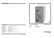
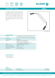
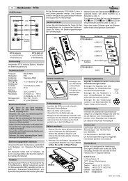
2.1 Pin Definition<br />
Pins are numbered as shown in Figure 1.<br />
LED (receive, green)<br />
LED (transmit, yellow)<br />
1 2 3 4 5 6 7 8 9 10 11 12<br />
whip antenna<br />
Figure 1 Component side view <strong>of</strong> the transceiver module<br />
7007