The Dangerous Music 2-Bus Manual
The Dangerous Music 2-Bus Manual
The Dangerous Music 2-Bus Manual

Create successful ePaper yourself
Turn your PDF publications into a flip-book with our unique Google optimized e-Paper software.
<strong>The</strong> <strong>Dangerous</strong> <strong>Music</strong> 2-<strong>Bus</strong> <strong>Manual</strong><br />
Thank you for choosing products from the exciting line of <strong>Dangerous</strong> <strong>Music</strong><br />
recording equipment. Many years of dependable and trouble-free<br />
performance can be expected from our gear. This has been made possible by<br />
careful design, construction, and top-shelf component choices by recording<br />
industry veterans. This manual will assist the user with installation of the<br />
2-<strong>Bus</strong>, as well as calibration of the system.<br />
Contents<br />
Introduction……………………………….. 1<br />
Safety review……………………………... 2<br />
Overview and Hook up…………………... 3<br />
Front Panel and Use………………………. 4<br />
Calibration………………………………... 5<br />
Grounding and Interface …………………. 6<br />
Balanced and Unbalanced connections....... 7<br />
Grounding revisited………………………. 8<br />
Connector Pin-Outs………………...…….. 10<br />
Specifications…………………………….. 11
<strong>Dangerous</strong> <strong>Music</strong> 2-<strong>Bus</strong> <strong>Manual</strong><br />
Safety Review<br />
Certain precautions should be taken when using electrical products. Please observe the safety hints by<br />
reading the manual and obtaining qualified help if necessary to adhere to the precautions. <strong>The</strong> power<br />
supply must be switched to the proper mains voltage. PLEASE CHECK THE RED WINDOW ON<br />
THE POWER SUPPLY TO VERIFY THE CORRECT SETTING FOR YOUR LOCATION<br />
BEFORE CONNECTING THE MAINS PLUG!<br />
1. Always use a properly grounded power supply cord with this product. Please do<br />
not defeat the ground pin on the mains plug. This connection provides earth to the chassis and<br />
signal grounds inside the device for clean and quiet operation. <strong>The</strong> “Grounding and interface”<br />
section can help the user/installer clear up a buzz problem if one develops.<br />
2. Avoid high temperature operation in equipment racks by providing air<br />
circulation. <strong>The</strong> number one killer of electronic gear is HEAT. Vented rack panels may look like<br />
wasted space to an interior decorator, but they look like beauty to a technician or equipment<br />
designer! If the front panel is hot, it is roasting inside the box.<br />
3. Avoid areas of high magnetic fields. <strong>The</strong> steel chassis of the <strong>Dangerous</strong> 2-<strong>Bus</strong> is<br />
designed to shield the circuits from EMI and RFI (magnetic and radio interference). When<br />
installing equipment in racks, it is prudent to put power amplifiers and large power supplies at<br />
least several rack spaces, if not in a different rack, away from equipment that deals with low-level<br />
signals. Separation of high level and low level equipment can pre-empt trouble caused by heat<br />
and EMI.<br />
4. Care should be taken to avoid liquid spills around equipment. If a spill occurs,<br />
please shut off the gear and disconnect the mains. A qualified technician should investigate<br />
accidents to prevent further equipment damage or personnel hazards caused by spills.<br />
5. If one is uncomfortable with opening gear and changing jumpers or making<br />
adjustments, please seek qualified help if necessary.<br />
6. If adjustments or jumper changes are required, please disconnect the mains plug<br />
before opening the top. Dropped screws or tools on a live circuit board can manifest themselves<br />
as burn marks and smoked components. While we feel your pain, (been there) subsequent damage<br />
is not covered by the warranty.<br />
<strong>Dangerous</strong> <strong>Music</strong> Incorporated reserves the right to change the specifications or modify the designs<br />
of its equipment. Sending in the registration card is our way of keeping in touch with users of our<br />
equipment should this become necessary. Registration information is always kept confidential and never<br />
disclosed to third parties for any reason. Company contact information is on the last page of this manual.<br />
<strong>The</strong> CE sign on this product signifies the fact that the 2-<strong>Bus</strong> has been tested and<br />
verified to conform to the applicable standards of 89/336/EEC. EN55103-1<br />
(emissions) EN61000-2 (immunity) and EN60065:2002 (safety requirements)<br />
2
<strong>Dangerous</strong> <strong>Music</strong> 2-<strong>Bus</strong> <strong>Manual</strong><br />
Overview<br />
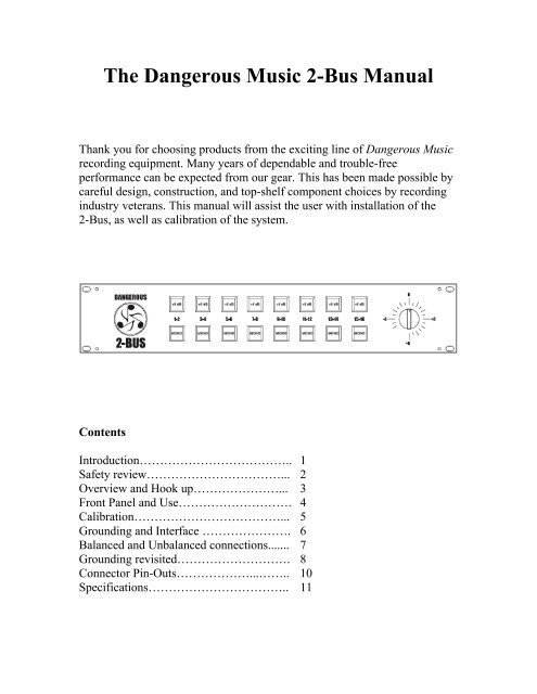
<strong>The</strong> 2-<strong>Bus</strong> is a 16x2 summing amplifier designed to help the users of digital audio<br />
workstations achieve better mix performance through the use of cutting-edge analog<br />
circuit design in conjunction with the existing equipment in their studios. <strong>The</strong> designers<br />
and their colleagues have noted that while DAWs offer unprecedented flexibility in<br />
multi-track recording and editing, the resulting mixes from these systems generally don’t<br />
equal those of high-end analog recording systems in terms of sound quality, preservation<br />
of spatial detail, headroom and ‘no latency’ ergonomics. In today’s portable environment<br />
and with the cost of maintaining and housing legendary recording equipment, the choice<br />
of a big desk is impractical for many users of DAW systems. We want to bring together<br />
the best of both worlds. It is in this spirit that the <strong>Dangerous</strong> engineering team is<br />
designing and manufacturing an exciting array of summing, mixing, monitoring,<br />
metering, and mastering equipment to meet the needs of today’s recording engineers,<br />
producers, and artists.<br />
Hook up<br />
<strong>The</strong> 2-<strong>Bus</strong> is designed to mix the outputs of up to 16 D/A converters to any stereo<br />
recorder (16x2). <strong>The</strong> 2-<strong>Bus</strong> is easily stackable to increase channel numbers and system<br />
functions when linked with other 2-<strong>Bus</strong>ses, Monitor, Monitor ST or 2-<strong>Bus</strong> LT. All of the<br />
XLRs are pin 2 hot, and the connector groups are described as follows:<br />
INPUT <strong>The</strong> inputs are arranged into eight pairs of XLRs. <strong>The</strong>y can be plugged<br />
into directly from the D/A converters but system flexibility (and fun) goes way up with<br />
the addition of a patch bay for ease of outboard equipment use.<br />
OUTPUT <strong>The</strong>re are two stereo outputs on the 2-<strong>Bus</strong>. <strong>The</strong> Main output goes to the<br />
mixdown recorder or A to D converter (or through mix buss compressors/EQs first, if<br />
desired). <strong>The</strong> Monitor output is identical to the main and is intended to feed a monitor<br />
controller (<strong>Dangerous</strong> Monitor or Monitor ST.).<br />
REM/EXP <strong>The</strong> remote/expansion connector allows for expandability of the system.<br />
<strong>The</strong> 2-<strong>Bus</strong> has a mix buss input on this connector to stack multiple 2-<strong>Bus</strong>es or link with a<br />
2-<strong>Bus</strong> LT. <strong>The</strong> pinout is on the Connector Pinouts page (p.10).<br />
DC IN <strong>The</strong>re is a grey power cable to hook the 2-<strong>Bus</strong> to its power supply. It is<br />
best to make sure that the power supply is off or unplugged when connecting the DC<br />
power cable to prevent damage to contacts in the connectors.<br />
3
<strong>Dangerous</strong> <strong>Music</strong> 2-<strong>Bus</strong> <strong>Manual</strong><br />
CHASSIS and GROUND <strong>The</strong> banana jacks are strapped together during assembly.<br />
<strong>The</strong>y are provided to accommodate grounding systems where the chassis and audio<br />
ground need to be separate.<br />
Front Panel and Use<br />
<strong>The</strong>re are three types of front panel controls on the 2-<strong>Bus</strong>.<br />
+6dB gain switches boost the signal patched to any pair of inputs<br />
MONO switches put the signals of a pair, normally panned hard left and right, up<br />
the middle of a mix.<br />
<strong>The</strong> Output Level Trim is a mix fine gain adjustment used to get the signal level<br />
just right to the mixdown A/D converter, recorder (or EQ/Compressor if in the<br />
chain).<br />
<strong>The</strong> switches on the front panel are laid out so that the inputs can be treated as stereo<br />
pairs (also known as “stems”) or as individual inputs panned up the middle of a mix. For<br />
sounds that are panned somewhere in between the two extremes, a pair of D/A converters<br />
is used, panning is done with your DAW’s software mixer and the Mono button is not<br />
engaged.<br />
For example, let’s say that one wants to mix a drum kit with bass, guitars, a lead<br />
vocal, and reverb signals together. To keep things simple, let’s say that the engineer has a<br />
DAW with 8 D/A channels available to patch to analog output processing if desired, and<br />
then the 2-<strong>Bus</strong>. This mix has 8 tracks of drums, one bass, two guitars, one vocal, with<br />
reverb and effects for maybe 2 dozen tracks total. Usually, a DAW user would mix this to<br />
2 tracks and then bounce the result to a new pair of tracks, but by using 4 pairs of outputs,<br />
audio flexibility can be improved by assigning the drums to DAW outputs 1 and 2, the<br />
bass and vocal to 3 and 4, the guitars to 5 and 6, and finally, the effects returns to 7 and 8.<br />
<strong>The</strong> bass and vocal want their own channels, so they are assigned straight to mono or<br />
direct outputs with no panning, and the MONO button on the 2-<strong>Bus</strong> is pressed to pan<br />
them up the middle. Maybe the drums need gain so the other outputs can be run hot. <strong>The</strong><br />
Gain button for inputs 1 and 2 would take care of this. <strong>The</strong> 2-<strong>Bus</strong> Main Output is then<br />
sent to an A/D converter that is recording back into the DAW (or an external device such<br />
as an editing system, tape machine, or CD burner) using the Output Trim Level to set the<br />
gain precisely. Since the tracks are spread among several busses in the computer, the<br />
individual levels can be run much hotter ‘inside the box’ resulting in a mix that has better<br />
clarity, detail, and punch. <strong>The</strong> use of outboard processing means that individual stems can<br />
be made to slam without using ‘outboard loops’ in the DAW and suffering another A/D<br />
conversion with the inherent time delay issues and another digital fader with its loss of<br />
4
U Volts<br />
U 9.76<br />
U 6.16<br />
U 1.23<br />
<strong>Dangerous</strong> <strong>Music</strong> 2-<strong>Bus</strong> <strong>Manual</strong><br />
detail. This example is a bare bones mix. <strong>The</strong> effect of setting up a system like this<br />
becomes more apparent as more tracks need to be mixed. <strong>The</strong> 2-<strong>Bus</strong> and 2-<strong>Bus</strong> LT are<br />
stackable to accommodate systems of any size.<br />
Calibration<br />
<strong>The</strong> following sections provide a more detailed look at some of the aspects of recording<br />
studio setup and trouble-shooting. While it is not absolutely necessary to read this<br />
material, we feel that a basic understanding of the principles of calibration, equipment<br />
interface, and grounding issues can go a long way to helping engineers before the going<br />
gets rough. If one encounters inconsistent levels or hum problems in the studio, the<br />
following hints may help in understanding the issues and resolving the problems. <strong>The</strong>se<br />
issues apply to recording gear in general, not just the 2-<strong>Bus</strong>.<br />
<strong>The</strong> <strong>Dangerous</strong> 2-<strong>Bus</strong> comes to you fully calibrated and ready to hook up. In order to<br />
enjoy the full benefits of a 2-<strong>Bus</strong> system, the D/A’s used with it should be aligned. This<br />
can be done with the aid of a Voltmeter or VU meter in a compressor or other piece of<br />
gear on hand) and the digital oscillator found as a plug-in in most DAW systems. While it<br />
is not necessary to align the system, better and more consistent mix results will be<br />
obtained if this is done. <strong>The</strong>re are two levels that most digital recording systems have<br />
seemed to converge on depending on whether the situation is for recording or mastering.<br />
<strong>The</strong> difference between the two worlds is whether the maximum electrical stress is<br />
imposed by amplitude limiting (recording) or slew-rate limiting (mastering).<br />
Professional recording systems in the US have historically used the VU meter for<br />
system alignment and level monitoring, so naturally, with many years of precedent, there<br />
are holdovers today from that system (derived from the telephone and broadcast<br />
industries). <strong>The</strong> standard of ‘0VU’ comes from the Bell Telephone engineers needing a<br />
convenient way to measure signal levels in phone lines and switching systems. 600 ohm<br />
balanced lines were the norm and 1 milliwatt of energy was a pertinent amount of juice<br />
moving through phone circuits. A ‘building out’ resistor was added to the VU meter to<br />
avoid loading the audio circuit down and the reference level cranked back up so the meter<br />
read ‘0VU’. <strong>The</strong> resulting standard level wound up at +4dBu, or roughly 1.23 volts AC<br />
RMS. This standard has been with us for more than 60 years now the world over and is<br />
the ‘reference level’ to which most professional audio systems are aligned.<br />
Alignment Chart<br />
AC VU dBu dBfs (recording) dBfs (mastering)<br />
v Tilt +22 0 (full scale) Tilt<br />
v Tilt +18 -4dBfs 0 (full scale)<br />
v 0 VU +4dBu -18dBfs -14dBfs<br />
5
<strong>Dangerous</strong> <strong>Music</strong> 2-<strong>Bus</strong> <strong>Manual</strong><br />
A/D converters in a recording situation are usually set to have a +22dBu maximum input<br />
level to achieve full scale. This allows for occasional loud hits to not clip the converter.<br />
D/A’s for this system would typically be aligned to have unity gain with the A/D’s. This<br />
is done by running a -18dBfs signal at 1 kHz with the digital oscillator to the individual<br />
D/A outputs one channel at a time. Turn the 2-<strong>Bus</strong> output gain knob all the way up and<br />
measure the voltage across pins 2 and 3 of the 2-<strong>Bus</strong> output connector. If there is a device<br />
in the studio that has a calibrated VU meter (<strong>Dangerous</strong> MQ, tape machine, compressor)<br />
patching the 2-<strong>Bus</strong> into it makes for convenient adjustment. Set the D/A converter gain<br />
so that the volume indicator reads 0 VU or 1.23 volts AC on the voltmeter.<br />
After the D/A’s are aligned, the A/D’s are aligned by using the oscillator and one<br />
of the D/A’s as a source. Feed that signal into the A/D’s one at a time and meter it in the<br />
DAW. Adjust the A/D for -18dB full scale. Once all the converters are aligned, the<br />
system becomes easier to handle because there is a wonderful consistency from channel<br />
to channel. This makes cross patching and bussing assignment seamless.<br />
Mastering systems are typically calibrated at -14dB from full scale for a<br />
maximum analog signal level of +18dBu. <strong>The</strong> reason for this is because mastered signals<br />
tend to be compressed and bright. <strong>The</strong>re is a lot of rapid change (slew-rate) in the signal<br />
that overloads processing gear and converters before the amplitude gets up to +22dBu.<br />
Some savvy 2-<strong>Bus</strong> users set their D/A converters as if they were mastering to be<br />
able to take full advantage of the dynamic range such a calibrated system has to offer. In<br />
other words, A/D’s are set to avoid clipping for recording and D/A’s are set to avoid<br />
overloading the mixdown converter. This is done by aligning one D/A at -18dBfs and<br />
using it to calibrate the A/D’s as above. <strong>The</strong>n set the all the D/A’s so that -14dB full scale<br />
is 0VU by running the digital oscillator at -14dB and adjusting the D/A output levels to<br />
read 1.23 volts AC or 0VU. This allows one to run the stems at hot levels without<br />
overloading the mixdown A/D converter.<br />
Grounding and Interface<br />
In order to achieve maximum performance of any recording system, the cables need to be<br />
wired properly. Following are diagrams of frequently encountered wiring scenarios to<br />
help explain some of the possibilities. We’ll start with professional, balanced, +4dBu<br />
levels encountered in most studio systems and then cover some contingencies that happen<br />
when interfacing -10dBV, unbalanced systems. Understanding this next bit is the key to<br />
quiet, reliable, and consistent studio operation.<br />
<strong>The</strong> balanced world is the easiest to deal with because the audio signals and the<br />
shield are kept separate down the interconnect cables. Properly wired systems with<br />
balanced interfaces can achieve impressive signal to noise ratios with the least amount of<br />
bother. Unbalanced equipment (RCA connectors or _” connectors with tip/sleeve) can be<br />
made to perform well but can be more bother because the signal reference voltage (the<br />
low side or ground) and the cable shield are one and the same, unbalanced connections<br />
having only 2 conductors in the cable. This sharing of signal and ground can cause<br />
trouble because stray ground currents become the reference for the audio signal. This<br />
situation can manifest itself as hum or buzzing sounds coming from the speakers and can<br />
be remedied with some tinkering and jumper placement. <strong>The</strong> 2-<strong>Bus</strong> is designed to make<br />
both types of connections easy and painless if some simple suggestions are followed.<br />
6
<strong>Dangerous</strong> <strong>Music</strong> 2-<strong>Bus</strong> <strong>Manual</strong><br />
Balanced Audio Connections<br />
<strong>The</strong> beauty of balanced connections is that they promote the idea that current should be<br />
prevented from flowing down cable shields while letting the audio pass. Pins 2 and 3<br />
carry a signal across them (transverse mode) and any interference that gets through the<br />
shield is picked up equally by the wires (common mode). <strong>The</strong> common mode noise is<br />
canceled by the differential action of the instrumentation amplifier in the first stage of the<br />
2-<strong>Bus</strong>. Signal gets through and the grounds stay put inside their respective pieces of gear.<br />
Unbalanced Audio Connections<br />
An unbalanced source driving a 2-<strong>Bus</strong> input usually presents no problem because<br />
of the differential action of the input stage.<br />
It is a good idea to use 3 wire cables even in an unbalanced situation because the<br />
2-<strong>Bus</strong> input can keep stray noise away from the signal even without the benefit of<br />
common mode rejection. If an unbalanced source gives one trouble, then this is usually<br />
because the source doesn’t have a proper ground reference. This is why there are Input<br />
Shield Lift jumpers inside the 2-<strong>Bus</strong> (and many other pieces of professional audio gear).<br />
7
<strong>Dangerous</strong> <strong>Music</strong> 2-<strong>Bus</strong> <strong>Manual</strong><br />
If a buzz is encountered, a quick test to see whether or not the jumper position should be<br />
changed is to hold a wire (a piece of speaker cable with bare ends or guitar cable tips)<br />
against a chassis screw of the source and the grounding post of the 2-<strong>Bus</strong>. If the buzz<br />
goes away, then the 2-<strong>Bus</strong> top should come off and the jumper position should be<br />
changed. We’ll repeat the appropriate cautionary notes from page two here:<br />
5. If one is uncomfortable with opening gear and changing jumpers or making<br />
adjustments, please seek qualified help if necessary.<br />
6. If adjustments or jumper changes are required, please disconnect the mains plug<br />
before opening the top. Dropped screws or tools on a live circuit board can manifest themselves<br />
as burn marks and smoked components. While we feel your pain, (been there) subsequent damage<br />
is not covered by the warranty.<br />
<strong>The</strong> jumpers are located on the main audio board where the input wires connect. <strong>The</strong><br />
inputs are labeled and in order so finding the correct jumper is easy. <strong>The</strong>se tactics rarely<br />
need to be performed but if they do, please work on a well-lit table or workbench. We<br />
always clean off enough space to have plenty of room so as not to lose screws and tools.<br />
Using a cloth or other pad underneath the equipment will prevent scratches and damage<br />
both to the gear and to the table.<br />
Next is a quick set of hints about where to look when trying to cure buzz troubles<br />
in a recording studio. While the techniques are not meant to be taken as Gospel (some<br />
techs might disagree with this treatise, so be it) these bits of knowledge were gleaned<br />
from decades of experience in test equipment use, manual reading, facility design,<br />
construction, trouble-shooting and being the chief of maintenance in some of the world’s<br />
top studios, as well as problem solving in the home studios of rock stars and remote<br />
recording/live sound situations. <strong>The</strong>se hints have proven to work in many situations while<br />
keeping systems safe and quiet.<br />
Grounding Revisited<br />
While the usual scenario in hooking up equipment is that one plugs in the cables and<br />
starts to work, the more complicated a system, the more likely it is that something will<br />
not work correctly as far as hum and noise performance is concerned. While some would<br />
blame the equipment, this is the equivalent of blaming the eggs for a bad soufflé. Usually,<br />
hum and noise problems (and jitter or clock troubles in digital interfaces) can be traced to<br />
poor planning and implementation of the studio’s grounding situation. It is illuminating<br />
to realize that the engineers of yore in the recording, broadcast, and communications<br />
industries have been through these troubles and figured out the solutions. History can<br />
teach us a lot about how to avoid ground loops and their associated problems. <strong>The</strong><br />
manuals of many test instrument and recording equipment manufacturers from the ‘50’s<br />
to the 80’s had chapters on how to fix hum and noise problems, and it is from this wealth<br />
of information that the writer draws ideas from for trouble free grounding schemes.<br />
8
<strong>Dangerous</strong> <strong>Music</strong> 2-<strong>Bus</strong> <strong>Manual</strong><br />
To comply with international standards and wiring practices, recording equipment<br />
manufacturers are required to connect all the shield pins of audio and data connectors to<br />
the chassis grounds of their gear. Sometimes, this can cause noise problems in large<br />
systems where pieces of equipment are spread out around a facility because two<br />
‘grounds’ are never quite at the same potential. This can cause ground loops (hums or<br />
buzzing) if the cable shields are allowed to connect two chassis that are at different<br />
potentials due to location, circuit wiring, or induction.<br />
If the audio cables between the racks connect the equipment grounds together via the<br />
shields and the racks are at even slightly different potentials (on different circuits with<br />
different loads, long distance, etc) the shields will try to equalize the potential difference.<br />
Juice will flow down the shields and broadcast hum into the signal wires they<br />
were supposed to protect or wind up imposed on the reference ground of the receiving<br />
equipment. This situation manifests itself as the all too familiar buzz of a ‘ground loop’.<br />
<strong>The</strong> intensity depends on many variables but can go from unnoticeable to raging. Some<br />
people in desperation resort to using AC plug “ground lifts” to defeat the mains safety<br />
grounds in a random fashion until the system quiets down a bit. This in our view (and the<br />
view of the safety standards organizations) is an unacceptable method of taming ground<br />
buzzes. <strong>The</strong> simpler way is to make sure that all the gear has a good mains ground and to<br />
lift the shields on the receiving ends of the audio cables. <strong>The</strong> principals at <strong>Dangerous</strong><br />
<strong>Music</strong> have wired up large, world-class facilities using this scheme and have brought<br />
room after room online with no buzz problems from the moment of power up. This is<br />
why many gear manufacturers have shield lift jumpers inside their equipment. If a noise<br />
problem crops up, changing the jumper position will almost always cure the problem.<br />
Planning out the wiring system to minimize the formation of ground loops solves<br />
problems before they happen.<br />
Many powered speakers seem to get their audio reference ground from the input<br />
cable. This means that these shields should not be lifted at the XLR. One favored<br />
technique for trouble shooting buzz issues is to make a short XLR cable with the shield<br />
lifted on the Male connector and use this to test whether or not an interface warrants a<br />
shield lift wiring permanently into its receiving end connector.<br />
9
<strong>Dangerous</strong> <strong>Music</strong> 2-<strong>Bus</strong> <strong>Manual</strong><br />
Sometimes problems that sound like ground loops are caused by other situations. <strong>The</strong>se<br />
require trouble shooting beyond the scope of this section and a qualified technician may<br />
have to make a visit if help is needed.<br />
Expansion Inputs and Connector Pin-Outs<br />
<strong>The</strong> 2-<strong>Bus</strong> has an expansion input port that allows connecting other 2-<strong>Bus</strong>es and 2-<strong>Bus</strong><br />
LT’s, to increase the system size and capability. <strong>The</strong> 25-way ‘D’ connector on the rear<br />
panel labeled REM/EXP is used for this purpose. <strong>The</strong> REM/EXP port is wired according<br />
to the following chart. A pre wired expansion adapter for the 2-<strong>Bus</strong> is available when<br />
multiple units are bought or additional units are ordered for a facility already using one.<br />
Pin# function<br />
10 right +<br />
23 right –<br />
11 right shield<br />
24 left +<br />
12 left –<br />
25 left shield<br />
All the XLR connectors are pin 2 hot.<br />
Pin 1 shield<br />
Pin 2 + signal<br />
Pin 3 - signal<br />
So far, we have not seen Pin 1 hot (+), except after too many drinks…<br />
<strong>The</strong> AC Mains cable<br />
<strong>The</strong> mains cable uses a standard IEC connector. Please check the mains voltage<br />
selector (the little red window next to the IEC connector on the power supply) to<br />
make sure that it is correct for your location. <strong>The</strong> fuses for the voltage selection block<br />
are _ ampere, fast blow AGC type. PLEASE DON’T PUT A FUSE OF LARGER<br />
RATING IN THE BLOCK! Disconnect the mains cable before changing the voltage<br />
or replacing a fuse. If a fuse blows repeatedly, this is a sign from Mother Nature that<br />
something is wrong and the factory should be contacted for help at the link provided on<br />
the Specifications page.<br />
Please use pre-wired AC cables for this device unless a technically qualified person<br />
makes the connections to a mains plug. In this case, use only high quality mains plugs<br />
like Hubbel, Thomas & Betts, or similar. Remember, in America, Black is hot, White is<br />
neutral, and Green is ground. In Europe, Brown is hot, Blue is Neutral, and Green with a<br />
Yellow stripe is ground. It is critical to get this correct. Double check that it is!<br />
10
<strong>Dangerous</strong> <strong>Music</strong> 2-<strong>Bus</strong> <strong>Manual</strong><br />
Specifications<br />
Frequency response………………….<br />
THD + Noise…………………………<br />
IMD60 4:1…………………………...<br />
Crosstalk Rejection………………….<br />
Noise floor…………………………...<br />
Maximum signal level………………..<br />
Nominal operating level……………...<br />
Input impedance……………………...<br />
Output impedance…………………….<br />
Gain accuracy………………………...<br />
Power consumption……………….…..<br />
Warranty…………………………….<br />
1 Hz – 100 kHz within 0.1dB<br />
0.0045% +4 dBu input level<br />
0.0008% +22 dBu input level<br />
0.0055% +4 dBu input level<br />
0.0015% +22 dBu input level<br />
>101dB @ 1 kHz<br />
0.02dB for any setting<br />
25 watts<br />
2 years parts and labor, subject to factory<br />
inspection. Does not include damage from<br />
accident, abusive operation, shipping, or<br />
modifications/attempted repairs by<br />
unauthorized personnel. Please contact the<br />
factory with questions or claims before<br />
shipping.<br />
<strong>Dangerous</strong> <strong>Music</strong>, Inc.<br />
USA<br />
Europe<br />
<strong>Dangerous</strong> <strong>Music</strong>, Inc.<br />
<strong>Dangerous</strong> <strong>Music</strong>, Inc.<br />
231 Stevens Road Stieleichenweg 55<br />
Edmeston, NY 13335<br />
50999 Köln<br />
Phone: 607 965-8011 Tel: +49.0.2236.393731<br />
Fax: 607-965-8012<br />
Email: info@dangerousmusic.com<br />
E-mail: info@dangerousmusic.de<br />
11