Fender Systems - Trelleborg
Fender Systems - Trelleborg
Fender Systems - Trelleborg

Create successful ePaper yourself
Turn your PDF publications into a flip-book with our unique Google optimized e-Paper software.
Unit Elements<br />
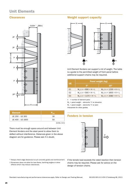
Clearances<br />
Weight support capacity<br />
(Min)<br />
Unit Element fenders can support a lot of weight. The table<br />
is a guide to the permitted weight of front panel before<br />
additional support chains may be required.<br />
UE<br />
Panel weight (kg)<br />
0° 10°<br />
E1 W H ≤ n × 690 × H × L W V ≤ n × 1230 × H × L<br />
E2 W H ≤ n × 900 × H × L W V ≤ n × 1600 × H × L<br />
E3 W H ≤ n × 1170 × H × L W V ≤ n × 2080 × H × L<br />
n = number of element pairs<br />
W H = panel weight – elements ‘V’ on elevation<br />
W V = panel weight – elements ‘V’ on plan<br />
Interpolate for other grades<br />
Element<br />
P min<br />
UE 250 – UE 300 30<br />
UE 400 – UE 1600 50<br />
[Units: mm]<br />
<strong>Fender</strong>s in tension<br />
There must be enough space around and between Unit<br />
Element fenders and the steel panel to allow them to<br />
deflect without interference. Distances given in the above<br />
diagram are for guidance. Please ask if in doubt.<br />
* Always check edge distances to suit concrete grade and reinforcement.<br />
† Dimension does not allow for bow flares, berthing angles or other<br />
effects which may reduce clearances.<br />
If the tensile load exceeds the rated reaction then tension<br />
chains may be required. Please ask for advice on the<br />
design of tension chains.<br />
Standard manufacturing and performance tolerances apply. Refer to Design and Testing Manual. M1100-S01-V1-3-EN © <strong>Trelleborg</strong> AB, 2013<br />
25