23inch to 37inch full motion mount PSW700AT - Loctek
23inch to 37inch full motion mount PSW700AT - Loctek
23inch to 37inch full motion mount PSW700AT - Loctek

Create successful ePaper yourself
Turn your PDF publications into a flip-book with our unique Google optimized e-Paper software.
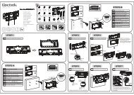
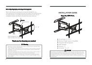
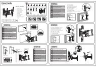
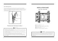
Part 4-Adjusting screen and using cord management<br />
Route cords along articulating arms using cord management wraps(10).<br />
Articulating arms can be adjusted <strong>to</strong> position screen in<strong>to</strong> desired location.<br />
Use allen wrench(7/8) <strong>to</strong> tighten and loosen the tension screw. Do not<br />
overtighten and do not loosen <strong>to</strong> the point the screws come out.<br />
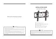
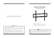
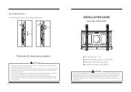
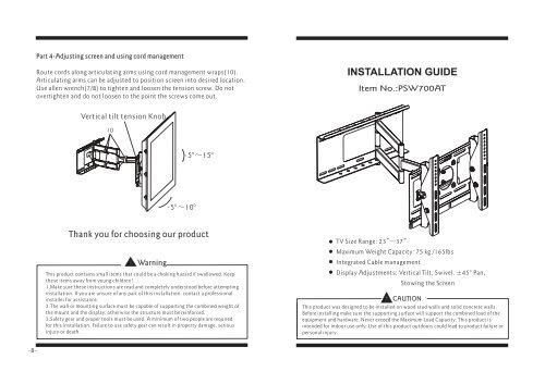
INSTALLATION GUIDE<br />
Item No.:<strong>PSW700AT</strong><br />
Vertical tilt tension Knob<br />
10<br />
-5° ~15°<br />
-5° ~10°<br />
Thank you for choosing our product<br />
Warning<br />
This product contains small items that could be a choking hazard if swallowed. Keep<br />
these items away from young children!<br />
1.Make sure these instructions are read and completely unders<strong>to</strong>od before attempting<br />
installation. If you are unsure of any part of this installation, contact a professional<br />
installer for assistance.<br />
2.The wall or <strong>mount</strong>ing surface must be capable of supporting the combined weight of<br />
the <strong>mount</strong> and the display; otherwise the structure must be reinforced.<br />
3.Safety gear and proper <strong>to</strong>ols must be used. A minimum of two people are required<br />
for this installation. Failure <strong>to</strong> use safety gear can result in property damage, serious<br />
injury or death.<br />
TV Size Range: 23" ~37"<br />
Maximum Weight Capacity: 75 kg /165lbs<br />
Integrated Cable management<br />
Display Adjustments: Vertical Tilt, Swivel, ± 45°<br />
Pan,<br />
S<strong>to</strong>wing the Screen<br />
CAUTION<br />
This product was designed <strong>to</strong> be installed on wood stud walls and solid concrete walls.<br />
Before installing make sure the supporting surface will support the combined load of the<br />
equipment and hardware. Never exceed the Maximum Load Capacity. This product is<br />
intended for indoor use only. Use of this product outdoors could lead <strong>to</strong> product failure or<br />
personal injury.<br />
-8-
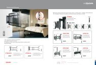
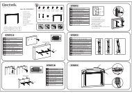
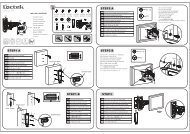
Hardware Kit:<br />
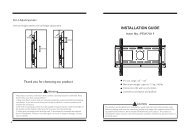
Part 3-Mounting the flat panel screen and installing locking bar<br />
7<br />
2<br />
8<br />
1<br />
9<br />
4<br />
5<br />
Hook the <strong>to</strong>p of brackets on<strong>to</strong> the <strong>to</strong>p flange of wall plate(1). Then swing<br />
the screen down. Slide security bars(5) between brackets and the bot<strong>to</strong>m<br />
edge of wall plate(1). Secure with padlocks(6).<br />
NOTE: Always use an assistant or mechanical lifting equipment <strong>to</strong> safely lift<br />
and position heavy equipment.<br />
10<br />
3<br />
6<br />
5<br />
Wall<br />
Wall<br />
5<br />
A-F<br />
G<br />
H<br />
I<br />
J<br />
K<br />
ID<br />
1<br />
2<br />
3<br />
4<br />
5<br />
6<br />
7<br />
8<br />
9<br />
10<br />
Qty<br />
1<br />
1<br />
1<br />
1<br />
2<br />
2<br />
1<br />
1<br />
1<br />
3<br />
Description<br />
Wall Plate<br />
Cantilever Arm<br />
Left Bracket<br />
Right Bracket<br />
Locking Bar<br />
Padlock<br />
6x6 Wrench<br />
5x5 Wrench<br />
4x4 Wrench<br />
Cord management wrap<br />
ID Qty<br />
A 4<br />
B 4<br />
C 4<br />
D 4<br />
E<br />
F<br />
G<br />
H<br />
I<br />
J<br />
K<br />
4<br />
4<br />
4<br />
6<br />
6<br />
6<br />
4<br />
Description<br />
M4×12mm<br />
bolt<br />
M4×16mm<br />
bolt<br />
M5× 16mm<br />
bolt<br />
M6×16mm bolt<br />
M5×36mm bolt<br />
M6×36mm bolt<br />
Square washer<br />
Long bolt<br />
Wall anchor<br />
Long bolt washer<br />
Spacer<br />
1<br />
3,4<br />
6 5<br />
-2- -7-
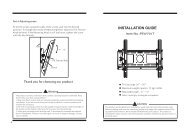
Part 2b-Attaching brackets <strong>to</strong> screen with recessed back<br />
Center brackets vertically on back of screen. Select the medium(E) or<br />
large(F) screws. Attach brackets <strong>to</strong> screen using four selected screws, four<br />
square washers(G) and four spacers(K) at the <strong>to</strong>p and bot<strong>to</strong>m of each<br />
bracket. Tighten screws firmly. Do not overtighten.<br />
Part 1a-Wood Stud Mounting<br />
Use wall plate(1) as a template, make sure it is level, and mark six <strong>mount</strong>ing holes<br />
along the center lines of the wood studs. Drill six 3/16” (5mm)dia.<br />
holes 2 ” (50mm)<br />
deep. Level wall plate(1) and attach <strong>to</strong> wall with six long bolts(H) and six washers(J ).<br />
Tighten screws firmly. Do not overtighten.<br />
Square washer(G)<br />
Large hole for<br />
M6 screws<br />
Medium hole<br />
forM5screws<br />
K<br />
G<br />
E-F<br />
2”(<br />
50mm)<br />
Φ3/16 ”(5mm)<br />
Wood stud<br />
Bubble level<br />
J<br />
H<br />
-6- -3-
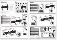
Part 1b-Concrete Wall Mounting<br />
Level wall plate(1) and use wall as a template <strong>to</strong> mark six holes. Drill six 3/8 ” (10mm)<br />
dia. holes 2 ” (50mm) deep. Insert six anchors(I) in<strong>to</strong> holes and secure wall plate<br />
with six long bolts(H) and six washers(J).Tighten screws firmly. Do not overtighten.<br />
Part 2a-Attaching Brackets To Screen With Flat Back<br />
Center brackets vertically on back of screen. Select the small(A or B),<br />
medium(C) or large(D) screws. Attach brackets <strong>to</strong> screen using four<br />
selected screws and four square washers(G) at the <strong>to</strong>p and bot<strong>to</strong>m of each<br />
bracket. Tighten screws firmly. Do not overtighten.<br />
2 ” ( 50mm)<br />
Square washer(G)<br />
Φ3/8 ”(10mm)<br />
Large hole for<br />
M6 screws<br />
Medium hole<br />
forM5screws<br />
G<br />
A-D<br />
Small hole for<br />
M4 screws<br />
Bubble level<br />
Concrete Wall<br />
I<br />
J<br />
H<br />
-4- -5-