Advanced- Butchers Block - Triton Tools
Advanced- Butchers Block - Triton Tools
Advanced- Butchers Block - Triton Tools

Create successful ePaper yourself
Turn your PDF publications into a flip-book with our unique Google optimized e-Paper software.
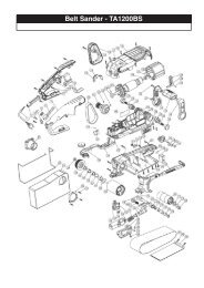
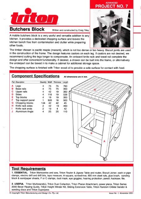
<strong>Butchers</strong> <strong>Block</strong><br />
Written and constructed by Craig Tilley<br />
A mobile butchers block is a very useful and versatile addition to any<br />
kitchen. lt provides a dedicated chopping surface and leaves the<br />
kitchen bench free from contamination and clutter while preparing<br />
other foods.<br />
The timber chosen is pacific maple (meranti), which is not too dense or too heavy. Biscuit joints are used<br />
in the construction of the frame. The design features castors on each leg. lf castors are not desired, we<br />
recommend cutting the legs longer to compensate. An onboard knife rack and towel rail complete the<br />
design and offer convenient functionality. lf desired, a drawer can be built into the frame, or alternatively<br />
the underpart can be boxed in to make a cabinet for additional storage space.<br />
The chopping surface is finished with <strong>Triton</strong> wood oil to provide a safe surface for contact with food.<br />
All dimensions are in mm.<br />
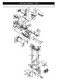
Paft Description<br />
A Legs<br />
B Base rails<br />
C Upper rails<br />
D Sides<br />
E Top blocks<br />
F Top support panel<br />
G Chopping blocks<br />
H Knife rack sides<br />
I Knife rack ends<br />
J Aluminium Angle<br />
Quantitv Width Thickness Lenoth<br />
4 75 75 760<br />
4 75 75 350<br />
4 42 19 350<br />
4 110 19 538<br />
4 19 19 350<br />
1 500 16 500<br />
144 42 42 45<br />
2 42 19 450<br />
219442<br />
4 25 25 110<br />
Tool Requirements<br />
1. ESSENTIAL <strong>Triton</strong> Workcentre and saw, <strong>Triton</strong> Router & Jigsaw Table and router, Biscuit Joiner, sash or pipe<br />
clamps, electric drill and drill bits, tape measure, tri-square, screwdriver, 600 mm steel rule, glue brush, sanding<br />
block & sandpaper sheets, F or C clamps, dust mask, eye goggles, hearing protection, pencil, hacksaw, file.<br />
2. USEFUL <strong>Triton</strong> Multistand(s), <strong>Triton</strong> Dust Collection, <strong>Triton</strong> Planer Attachment, power plane, <strong>Triton</strong> Series<br />
2000 Bevel Ripping Guide, <strong>Triton</strong> Height Winder Kit, Sliding Extension Table, <strong>Triton</strong> Random Orbital Sander &<br />
sanding discs and <strong>Triton</strong> Superjaws<br />
@ Copyright <strong>Triton</strong> Manufacturing and Design Co. Pty. Ltd. /ssue No. 1. November 2001
Construction details<br />
1. WOOD<br />
Meranti<br />
75x75-2@24OOm<br />
45x45-3@3000m<br />
110x19-1 @2400m<br />
MDF (for top support panel)<br />
16mm-1@600x900<br />
2. FASTENING<br />
<strong>Triton</strong> Premium Woodworking Adhesive,<br />
<strong>Triton</strong> biscuits (24),<br />
Woodscrews:8G x 30 mm (51),<br />
Roundhead screws: 6G x 20 mm (16).<br />
3. OTHER<br />
Swivelcastors 50 mm with locks (4), towel rail (480<br />
mm long).<br />
The 19 x 19 top blocks (E) can also be ripped to width<br />
while the Workcentre is in the tablesaw mode. lf<br />
necessary, plane the cut faces of these pieces using the<br />
<strong>Triton</strong> Planer Attachment to remove the marks from the<br />
saw blade.<br />
From these pieces, cut the upper rails (C) to length as<br />
for the legs. All four rails can be clamped together to do<br />
4. FINISHING<br />
Wood stain and estapol or undercoat and paint of<br />
your choice. Chopping block surface can be oiled<br />
with <strong>Triton</strong> Interior Wood Finishing Oil.<br />
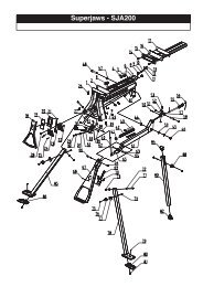
Begin construction by cutting the legs<br />
I length. Cut one end of each leg squar one<br />
r<br />
pass of the saw. Note: Double cuts m<br />
required to achieve this cut depth with small saws.<br />
Turn the legs around and line up their cut ends. Clamp<br />
them together with an F clamp, two at a time and cut<br />
them to length with a second pass of the saw. Repeat<br />
for the other two legs (Fig. t).<br />
Mark the legs for attachment to the rails. The<br />
upper rails are positioned flush with the tops of<br />
the legs. The base rails are positioned 200 mm<br />
up from the bottom of the legs. Mark a pencil line onto<br />
the legs to show where the rails will fit so the biscuit cuts<br />
can be made in the correct places (Fig. 4).<br />
Next, cut the four base rails (B) using the same<br />
technique as the legs. Sand the ends of the rails<br />
and legs smooth in preparation for cutting the<br />
biscuit slots.<br />
The upper rails (C) are cut next to a width of 19<br />
mm. Use the Workcentre in the tablesaw mode.<br />
Rough cut one of the 2.4 m lengths ot 42 x 42lo<br />
a 1.6 m piece. Rip this down the centre, creating lwo 42<br />
x 19 pieces (Fig. 2).
Cut the biscuit joints using the <strong>Triton</strong> Biscuit<br />
Joiner. The joints in the legs for the upper rails<br />
are cut first. This joint uses a single biscuit,<br />
whereas the base rails use two biscuits per joint.<br />
Set up the <strong>Triton</strong> Biscuit Joiner so the cutter will cut<br />
8mm in from the edge. Cut single slots in the positions<br />
marked on the legs for the upper rails. Use the sliding<br />
guide to help make these cuts.<br />
Cut matching slots in the ends of the upper rails with the<br />
sliding guide still in place (Fig. 5).<br />
Check that everything is square by measuring the<br />
diagonals. Adjust the clamps until both measurements<br />
are identical.<br />
Do the same for the two other legs, an upper rail and a<br />
base rail.<br />
When the glue is dry, join the two frame halves<br />
together with the remaining rails in place. Clamp<br />
the assembly together and check the frame for<br />
square (Fig. 8). Allow the glue to dry.<br />
Next, remove the sliding guide and adjust the<br />
cutter height to 22mm. Cut double slots for the<br />
base rails as marked.<br />
To cut a double slot, cut one slot, then turn the leg over<br />
onto the opposite face and cut the other slot (Fig. 6).<br />
Replace the sliding guide and cut the double biscuit<br />
joints in the ends of each of the base rails.<br />
Do a dry run without glue to check the position of<br />
the biscuit joints. When all joints have been<br />
tested, set up to glue together two legs, an upper<br />
rail and a base rail.<br />
Apply a good quality PVA (<strong>Triton</strong> Premium Woodworking<br />
Adhesive is ideal) and two pipe clamps (or sash cramps)<br />
to hold the joints together while the glue dries (Fig. 7).<br />
Smear glue on both sides of the biscuits and the mating<br />
surfaces using a small paintbrush. Wipe off any glue<br />
that spills out of the joints with a damp cloth as the<br />
clamps are tightened.<br />
While this dries, prepare the top blocks (E).<br />
These are attached to the insides of the upper<br />
rails and to the top support panel (F) with glue<br />
and two 8G x 30 mm woodscrews. (Fig. 9)<br />
Drill clearance and countersink holes for the attachment<br />
screws (two in each block) and for the screws that will<br />
attach later to the top support panel (three in each block).
I 0 Hl,,:#ff',f"Titil1""."il:"".fl<br />
i?"<br />
Drill three clearance and countersink holes through the<br />
lower paft of each of the upper rails for the 8G x 30 mm<br />
screws that will hold the sides to the rails.<br />
Next cut the sides (D) to length in the<br />
tablesaw mode. Allow for the overlap of the<br />
bevels. Use the protractor to guide your<br />
I<br />
The chopping blocks (G) sit on the top<br />
support panel (F). Cut this panel from<br />
16mm in the tablesaw mode then sand the<br />
edges smooth.<br />
I 3 8i:r<br />
Mark and drill<br />
two holes in<br />
each face of the<br />
angle, offset on<br />
each side<br />
slightly, for 6G x<br />
12 mm round<br />
head screws<br />
(Fis. r 2). The<br />
holes are offset<br />
so the screws<br />
won't hit each other when they are installed.<br />
Cut the bevels on the Workcentre using either the 45'<br />
face of the Series 2000 fence or the Bevel Ripping<br />
Guide set at 45" (Fig. rO).<br />
lf you don't have either of these, use the Workcentre in<br />
the crosscut mode with the power saw set at a 45'<br />
angle.<br />
Screw the sides in place dry first to check the bevels fit<br />
snugly together. Aluminum angle (J), fitted in Step 13,<br />
will cover any imperfections in these joints.<br />
When you're happy with the joints, glue and screw the<br />
sides in place through the holes drilled earlier (Fig. f 1).<br />
Screw the angles in place at each corner with the four<br />
screws (Fig. 13).<br />
A Prepare the Chopping <strong>Block</strong> assembly )<br />
I f+ cutthg the three 3.0m lengths of 45<br />
9I<br />
45mm into 12 pieces 750mm long.<br />
Rip or plane them down to 45 x 42mm.<br />
Lay them down on a flat surface with the 42mm sides<br />
vertical and their ends in line, then cramp them together.<br />
Check that the overall width is approximately 502 -<br />
506mm.
I ] Ensure the assembly is square then scribe<br />
I I $:'"xT".'"'#?#'"i?n:ffi:grliiil ff:'<br />
guides for cutting biscuit slots and will aid in the final<br />
alignment when gluing the assembly.<br />
Trim strips of blocks by setting the rip fence<br />
to, say 44mm, then machining one side of<br />
each strip first. Then set the fence to 42mm<br />
and machine the other side, to provide 12 strips of<br />
blocks 42mm wide and 45mm high.<br />
^]<br />
Use the <strong>Triton</strong> Biscuit Joiner to cut biscuit<br />
I o 2<br />
:::l;:l ili:"#ilff :x."?,';,Y3'il,lli.,n",<br />
as marked on the Biscuit Joiner.<br />
I<br />
r6)<br />
As described in Step 17 glue all 12 strips to<br />
one another and also to the support panel<br />
using G or F clamps and straight packers.<br />
I<br />
Apply glue liberally and assemble all 12<br />
pieces using <strong>Triton</strong> Biscuits, cramping at<br />
each end and in the centre.<strong>Triton</strong> Superjaws<br />
is idealfor supporting and cramping the assembly in the<br />
centre while fitting the sash (or pipe) cramps at the<br />
ends. (Fig. 14)<br />
Remove excess glue with a damp cloth. Allow 2-3 hours<br />
for the glue to dry then release all clamping.<br />
I<br />
Use the <strong>Triton</strong> Sliding Extension Table in the<br />
sliding mode to remove 50mm off each end<br />
of the assembly. Alternatively cut them in the<br />
crosscut mode. (This will remove the portion of the<br />
24<br />
assembly which included the end biscuits).<br />
I 9 [i:: SHrsT:;"J $""f[:::y?'''J<br />
grain from each end, providing 12 strips of<br />
12 blocks glued together. (Fig. 15)<br />
22<br />
When the glue has cured, trim the chopping<br />
block assembly to size (nominally 500 x<br />
50Omm) and square to suit the assembled<br />
Fix the chopping block assembly to the<br />
stand via screws through the top blocks.<br />
This is best done by inverting the stand with<br />
the chopping block sitting on a clean flat surface.<br />
Cut the parts for the knife rack (H & l) on the<br />
Workcentre. Attach the knife rack ends<br />
between the knife rack sides with olue and<br />
clamp them in place with F or C clamps (Fig. f 7).<br />
Mount the knife rack with three 8G x 30 mm screws<br />
driven from behind one of the sides, which will also<br />
conceal the screw heads.
Attach the towel rail on the opposite side of<br />
the chopping block with the screws supplied<br />
with the rail (Fig. l8).<br />
27<br />
Sand the project smooth and dust it off<br />
using a vacuum cleaner or cloth to remove<br />
all traces of sanding dust. This is essential<br />
to produce a really smooth surface when applying the<br />
desired finish. Apply the desired stain and estapol,<br />
sanding lightly between coats.<br />
The top surface of the chopping block is oiled (Fig. 2O).<br />
<strong>Triton</strong> Interior Wood Finishing Oil is pedect for this job,<br />
as it is safe for surfaces that come in contact with food.<br />
Check that the chopping block stands level<br />
on its legs and doesn't rock. lf necessary<br />
trim any offending legs, or insert shims<br />
beneath the castors to compensate for any movement.<br />
Chamfer the base of each leg slightly by hand sanding<br />
the edge at a 45' angle.<br />
Lay the chopping block on its side and mount the<br />
castors to the base of the legs with 8G x 30 mm screws<br />
or similar (Fig. 19). lt is important to buy swivel castors<br />
with locks that will prevent the chopping block from<br />
moving when in use.<br />
Apply it liberally with a brush. Wipe off the excess with a<br />
clean cloth, or try the burnishing method - as detailed on<br />
the can. lf the chopping block has been estapoled, apply<br />
a final coat of Wood Oilwith a clean cloth (Fig. 21).<br />
Alternatively, use a vegetable oil on the surface.<br />
As the chopping block is joined using a water based<br />
adhesive, saturation of the surface, during use, should<br />
be avoided. Keep clean using a damp cloth and re-oil<br />
regularly.