Simple Picture Framing - Triton Tools
Simple Picture Framing - Triton Tools
Simple Picture Framing - Triton Tools

Create successful ePaper yourself
Turn your PDF publications into a flip-book with our unique Google optimized e-Paper software.
You can make it with<br />
<strong>Simple</strong> Pictu re <strong>Framing</strong><br />
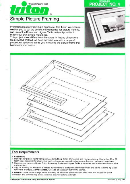
Professional picture framing is expensive. The <strong>Triton</strong> Workcentre<br />
enables you to cut the perfect mitres needed for picture framing,<br />
and use of the Router and Jigsaw Table makes it possible to<br />
shape your own simple mouldings.<br />
This project sheet differs from the others in that no dimensions<br />
are provided. Instead, we have provided you with a range of<br />
procedural options to guide you in making the picture frame that<br />
best meets your needs.<br />
3tD<br />
&"u<br />
Tool<br />
1. ESSENTIAL<br />
1. Making your picture f rame f rom purchased moulding: <strong>Triton</strong> Workcentre and your power saw, f itted with a 40 or 60<br />
tooth blade (essential for clean mitre cuts), mitre square or combination square, hammer, nail punch, sandpaper.<br />
2. Shaping your own mouldings: <strong>Triton</strong> Accessory Router and Jigsaw Table, your router, and a selection of decorative<br />
router cutters.<br />
3. A jig for working on end grain is needed if you intend to strengthen the mitres by use of a spline (See the Jig Guide<br />
for details of the jig). A small handsaw will also be necessary to trim the splines.<br />
2. USEFUL: Mitre corner clamps to aid assembly, an extension fence mounted onto Face A of the double-sided<br />
protractor, and a mitred stop block, to ensure accurate cutting to length.<br />
@ Copyright <strong>Triton</strong> Manufacturing and Design Co. Pty. Ltd. /ssue No. 2, July 1989
Construction Details<br />
Material Shoppinq List<br />
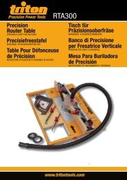
1. WOOD Any seasoned, straight-grained timber is<br />
suitable. To determine the total length of your frame<br />
material, the standard equation is: Twice the length<br />
plus twice the width of the picture, plus eight times the<br />
width of the moulding. Add about 300-500mm for<br />
cutting and waste. (Figure 1.)<br />
2. FASTENING Wood glue (PVA or similar) and<br />
25mm panel pins usually hold a picture frame<br />
together. The mitred corners can be strengthened by<br />
the addition of splines, (as shown in Step 9 & 10).<br />
3. OTHER All prints or paintings on paper, (as<br />
opposed to canvas) should be protected by use of a<br />
rnat board and glass. A suitable backing board is also<br />
needed. ("Mount Board" is generally available from art<br />
supply shops). Brown paper and masking tape protect<br />
the back of the picture from dust entrv.<br />
q)<br />
(.)<br />
<strong>Picture</strong><br />
W i dth of P i ct u re ------+t<br />
I<br />
1. This project sheet deals only with the<br />
making of a timber picture frame; most<br />
libraries have books on mat and glass cutting,<br />
but you may prefer to have this done<br />
professionally.<br />
2. When shaping mouldings, experiment on<br />
scrap pieces of wood to determine attractive<br />
combinations of decorative cuts.<br />
Shaping The Moulding<br />
Mouldings can be cut easily and quickly<br />
- using the Router and Jigsaw table in the<br />
Shaper Table mode.<br />
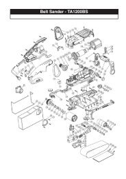
Figure 2 displays four examples from the range of<br />
decorative cutters available from our Customer<br />
Service Department.<br />
Also, in some cases, it is possible to turn your<br />
wood onto its edge or face down to achieve<br />
different effects.<br />
Quite complex frame moulding can be created.<br />
The frame illustrated on the title page was made<br />
using a large core box bit for the coving cut, a<br />
Roman Ogee bit and a Rounding-over bit.<br />
(Figure 3) Take care to ensure that the workpiece<br />
has adequate support when cutting complex<br />
mouldings.<br />
ROMAN ROUNDING 45O<br />
OGEE BIT<br />
FIGURE 2<br />
OVER CHAMFERING<br />
CARBIDE<br />
TIPPED<br />
COVE BIT<br />
FIGURE 1<br />
Shaping should always be done with your<br />
fences in line. Do not attempt to cut the<br />
complete profile in one pass, but rather<br />
make two or three shallow passes, with the cutter<br />
initially well back between the fences. As each cut<br />
is made, reset the fences until the cutter is<br />
completely proud for the final pass.<br />
The use of a cutter with a ball bearing or high<br />
speed steel pilot - in combination with the router<br />
table fences - further ensures safe and accurate<br />
cutting.<br />
Notes<br />
Two most important safety points in shaper<br />
table operation are:<br />
o You must always feed against the direction<br />
of rotation, never with it.<br />
. Never trail your fingers behind the<br />
workpiece in the vicinity of the cutter.<br />
Rebating the Moulding<br />
A rebate is needed in the back of the<br />
moulding deep enough to house the glass,<br />
mat, picture and backing board assembly, plus a<br />
little extra to drive fixing brads into. The rebate<br />
width should be about 8-10mm.<br />
This rebate can be cut in two ways. The first is to<br />
use a straight cut router bit, the fences in line.<br />
Progressively widen the rebate by moving the<br />
fences back after each cut. The cutter can be set<br />
at full height, as long as only about half the<br />
diameter of the cutter is actually in the timber.
th/Width of <strong>Picture</strong><br />
Outside edge of moulding<br />
FIGURE 4<br />
Alternatively, cut the rebate using your saw<br />
with the Workcentre set up in the table saw<br />
mode.<br />
The first cuts should always be made on edge. lf<br />
you have a severely rounded over edge on your<br />
moulding which prevents proper support of the<br />
workpiece, it would be better to do this rebating<br />
using the router, as per Step 3.<br />
A safe method of using the saw to cut a rebate in<br />
these circumstances is the use of a plywood or<br />
hardboard "mask" and a high rip fence extension,<br />
as discussed in the Operating Manual under<br />
"Edge Work on Thin Material".<br />
Also, refer to either the Operating Manual or the<br />
"Bread Board" project for safe operating<br />
procedures when edge rebating.<br />
At the completion of the rebating, crosscut the<br />
frames to approximate length. Cut each frame<br />
piece about 100mm oversize.<br />
Mitre Cutting The Moulding<br />
Dependent upon the length and/or<br />
thickness of your moulding, the mitre cuts<br />
can be performed either in the table saw mode, or<br />
the crosscut mode. Heavy or long mouldings are<br />
better cut in the crosscut mode, where the material<br />
can be held firmly, and the protractor clamped to<br />
the worktable if necessary. The basic procedures<br />
are the same in either case.<br />
The double sided protractor, with its A and B<br />
faces, makes possible mitre cuts that always add<br />
up to exactly 90 degrees. (This protractor was<br />
introduced with the MK.3 New Series; owners of<br />
earlier model MK.3 or later model MK.2 <strong>Triton</strong><br />
Workcentres can purchase this as an accessory<br />
item from our Customer Service Department).<br />
Face A is defined as the face closest to the<br />
calibrated scale.<br />
A Even though the double-sided protractor<br />
||r| ensures that mitres will add to 90 degrees,<br />
V<br />
make sure that the protractor is set as close<br />
to 45 degrees as possible. lf the mitres are cut at,<br />
say 46 degrees and 44 degrees, there will be some<br />
overlap on the corners.<br />
FIGURE 5<br />
Test on scrap and adjust if necessary. When<br />
correct, cut one end of all your frame pieces<br />
against Face B of the protractor, holding the<br />
outside (non-rebated) edge of the moulding firmly<br />
against the protractor to prevent creep.<br />
Measure and mark for your completed<br />
picture size, noting that the size is measured<br />
from the inside corner of the rebate (as per<br />
Figure 4). You can use the mat itself to mark this<br />
point, by placing it inside the rebate. Use a mitre<br />
square to extend your marked point to the edge of<br />
the framing and mark the edge where it will be<br />
visible during cutting.<br />
Now attach a straight batten to Face A of the<br />
protractor, to serve as an extension fence.<br />
Place one of the longer frame pieces against<br />
this extension, line up your mark with the saw cut<br />
line, and make the cut. As it may be difficult to see<br />
the mark clearly, play it safe and creep up to the<br />
mark with shaving cuts. Check the picture size<br />
against your frame.<br />
When you are satisfied that your frame size is<br />
correct, set the stop block by holding the frame<br />
side that you have just cut against the extension<br />
with the mitred cut just touching the blade (with<br />
the power off!). The stop should be placed at the<br />
other end, as shown in Figure 5. Remove the first<br />
workpiece and place the other longer side against<br />
the stop block and cut to length.<br />
The above procedures are repeated for the shorter<br />
frame sides.
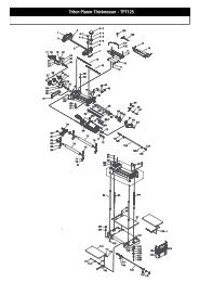
Construction Details<br />
METHOD A<br />
METHOD B<br />
FIGURE 6<br />
Spline For Strength<br />
A simple mitred joint is not particularly<br />
strong, relying on limited surface gluing and<br />
nails inserted into end grain. The joint can be<br />
substantially strengthened by the inseftion of a<br />
small spline. You will need both a 45 degree endgrain<br />
jig and a high fence extension mounted on<br />
your rip fence, as shown in the Jig Guide.<br />
You will also need a small amount of material, the<br />
thickness of your saw blade kerf, for the spline.<br />
You can use thin plywood (3mm thick for<br />
tungsten-carbide tipped saw blades), or you can<br />
make your own.<br />
lf you make your own spline material, make sure<br />
you prevent the narrow off-cut from jamming in<br />
the blade slot. Switch off the power just before<br />
finishing the cut, wait till the blade stops, withdraw<br />
the workpiece and break off your spline material.<br />
f tl<br />
lt is important that the splines are<br />
I u ?:'::?LXl {tliil::H ?1i!: [::]'Jti<br />
exactly in the centre of your workpieces. Measure<br />
the thickness of your material, halve it, allow for<br />
half the thickness of your saw kerf, and set your<br />
rip fence to suit.<br />
Test on scrap pieces of your moulding to check<br />
for accuracy, running your material on edge over a<br />
lowered saw blade, making cuts into each edge,<br />
and re-setting the rip fence, until the saw kerfs line<br />
up exactly.<br />
(This takes some time and careful adjustment of<br />
the fence. Any error in the fence setting is<br />
effectively doubled when making cuts with<br />
alternate faces against the fence).<br />
I r I !<br />
The spline cuts can be made in two ways.<br />
Figure 6 shows the options. Use method<br />
A for small, light mouldings; method B fo*<br />
large. l.,lote that with method A, it is possible that<br />
the spline will be visible on the inside edge of the<br />
frame. Also, in either case, if the rebate is deep<br />
relative to the thickness of the moulding, you may<br />
also need to trim the spline to clear the rebate.<br />
In both cases, the spline cuts are made first on<br />
one mitred end of each frame piece with the<br />
moulding face running against the fence<br />
extension. Then cut the other ends of your frames<br />
with the rebated face against the fence. (This is<br />
why it is crucial that your saw cut is central to your<br />
workpieces). Figure 7 demonstrates the<br />
procedure.<br />
You will cut into the angled leg of your jig when<br />
making these cuts. lt is advisable to "pre-cut" this<br />
jig slot, which helps to make a smooth pass over<br />
the saw when actually cutting the workpieces.<br />
Feed the jig and the workpieces slowly over the<br />
saw blade, don't pull the jig or workpiece back<br />
over the spinning blade, and keep your fingers<br />
well clear.<br />
f A Assembly<br />
| .t Do a trial assembly of the frame on a flat<br />
I r<br />
surface, rebate up, and check that the<br />
glass and backing fit correctly.<br />
When satisfied with the fit, glue and clamp with<br />
mitre clamps. lf using the splines, glue in position<br />
and carefully trim back when the adhesive has set,<br />
using a small handsaw. Two brads at each corner<br />
helo to secure the frame.<br />
Apply a finish of your choice to your picture<br />
frame, and then complete the assembly. Fit the<br />
glass (make sure the inside surface is clean), the<br />
mat, the picture (taped into position onto the mat<br />
to stop it shifting around), and the backing boaro.<br />
-<br />
Fix in place with a few small brads into the sides of<br />
the frame. Apply brown paper and tape to the<br />
back of the picture to keep out the dust.