fire resistance of reinforced concrete filled steel columns
fire resistance of reinforced concrete filled steel columns
fire resistance of reinforced concrete filled steel columns

Create successful ePaper yourself
Turn your PDF publications into a flip-book with our unique Google optimized e-Paper software.
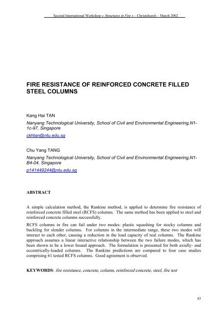
Second International Workshop « Structures in Fire » – Christchurch – March 2002<br />
FIRE RESISTANCE OF REINFORCED CONCRETE FILLED<br />
STEEL COLUMNS<br />
Kang Hai TAN<br />
Nanyang Technological University, School <strong>of</strong> Civil and Environmental Engineering,N1-<br />
1c-97, Singapore<br />
ckhtan@ntu.edu.sg<br />
Chu Yang TANG<br />
Nanyang Technological University, School <strong>of</strong> Civil and Environmental Engineering,N1-<br />
B4-04, Singapore<br />
p141449244@ntu.edu.sg<br />
ABSTRACT<br />
A simple calculation method, the Rankine method, is applied to determine <strong>fire</strong> <strong>resistance</strong> <strong>of</strong><br />
<strong>reinforced</strong> <strong>concrete</strong> <strong>filled</strong> <strong>steel</strong> (RCFS) <strong>columns</strong>. The same method has been applied to <strong>steel</strong> and<br />
<strong>reinforced</strong> <strong>concrete</strong> <strong>columns</strong> successfully.<br />
RCFS <strong>columns</strong> in <strong>fire</strong> can fail under two modes: plastic squashing for stocky <strong>columns</strong> and<br />
buckling for slender <strong>columns</strong>. For <strong>columns</strong> in the intermediate range, these two modes will<br />
interact to each other, causing a reduction in the load capacity <strong>of</strong> real <strong>columns</strong>. The Rankine<br />
approach assumes a linear interactive relationship between the two failure modes, which has<br />
been shown to be a lower bound approach. The formulation is presented for both axially- and<br />
eccentrically-loaded <strong>columns</strong>. The Rankine predictions are compared to four case studies<br />
comprising 61 tested RCFS <strong>columns</strong>. Good agreement is observed.<br />
KEYWORDS: <strong>fire</strong> <strong>resistance</strong>, <strong>concrete</strong>, column, <strong>reinforced</strong> <strong>concrete</strong>, <strong>steel</strong>, <strong>fire</strong> test<br />
43
Second International Workshop « Structures in Fire » – Christchurch – March 2002<br />
INTRODUCTION<br />
Fire <strong>resistance</strong> <strong>of</strong> <strong>reinforced</strong> <strong>concrete</strong> <strong>filled</strong> <strong>steel</strong> (RCFS) <strong>columns</strong>, which is traditionally<br />
determined by expensive furnace tests, presents a formidable problem to structural engineers.<br />
1. Steel tube <strong>of</strong> RCFS <strong>columns</strong> s<strong>of</strong>tens quickly at elevated temperatures and the load is<br />
transferred to the cooler <strong>concrete</strong> core, which is <strong>reinforced</strong> by <strong>steel</strong> reinforcement.<br />
Therefore, the <strong>concrete</strong> core largely determines the load capacity <strong>of</strong> RCFS <strong>columns</strong>, with<br />
only small contribution from the <strong>steel</strong> tube.<br />
2. The moment capacity <strong>of</strong> <strong>steel</strong> tube is also greatly reduced. This phenomenon is particularly<br />
detrimental to <strong>columns</strong> with <strong>steel</strong> tubes <strong>filled</strong> with plain <strong>concrete</strong>, as the <strong>concrete</strong> section<br />
cannot resist bending moment by itself. At ambient temperature, such a column can resist<br />
large bending moment by the <strong>steel</strong> tube. However, when subjected to elevated temperatures,<br />
the moment capacity <strong>of</strong> the column diminishes quickly as the <strong>steel</strong> tube s<strong>of</strong>tens. This will<br />
likely lead to a loss <strong>of</strong> ductility and thus a premature failure, as observed by Lie and Stringer<br />
[1]. As a general comment, only design plain <strong>concrete</strong> <strong>filled</strong> <strong>steel</strong> (PCFS) <strong>columns</strong> to carry<br />
axial loads in <strong>fire</strong> conditions. Where load eccentricity is anticipated, <strong>reinforced</strong> <strong>concrete</strong><br />
<strong>filled</strong> <strong>steel</strong> (RCFS) <strong>columns</strong> should always be used.<br />
3. The confinement effect to the <strong>concrete</strong> core will also diminish as a result <strong>of</strong> the s<strong>of</strong>tening <strong>of</strong><br />
<strong>steel</strong> tube.<br />
This paper outlines a simple analytical method, the Rankine method, to determine the <strong>fire</strong><br />
<strong>resistance</strong> <strong>of</strong> <strong>reinforced</strong> <strong>concrete</strong> <strong>filled</strong> <strong>steel</strong> (RCFS) <strong>columns</strong>. The same method has been<br />
applied to <strong>steel</strong> <strong>columns</strong>, <strong>steel</strong> frames, and <strong>reinforced</strong> <strong>concrete</strong> <strong>columns</strong> successfully [2 - 4]. The<br />
Rankine predictions are compared to four case studies comprising <strong>of</strong> 61 tested RCFS <strong>columns</strong><br />
and good agreement is observed.<br />
RANKINE FORMULA<br />
The Rankine formula for <strong>columns</strong> under <strong>fire</strong> conditions has the following form:<br />
1 1 1<br />
= +<br />
(1)<br />
P ( t)<br />
u P ( t)<br />
P ( ) t<br />
R<br />
pr<br />
p<br />
e<br />
with P R predicted failure load by the Rankine formula;<br />
u pr reduction factor <strong>of</strong> the plastic squashing load due to load eccentricity;<br />
P p plastic squashing load;<br />
u pr P p short column capacity;<br />
P e elastic buckling load;<br />
t <strong>fire</strong> exposure time; t = 0 for ambient conditions.<br />
The theoretical basis <strong>of</strong> the above formula has been discussed by Tang et al [2]. RCFS <strong>columns</strong><br />
in <strong>fire</strong> can fail under two modes: plastic squashing for stocky <strong>columns</strong> and buckling for slender<br />
<strong>columns</strong>. For <strong>columns</strong> in the intermediate range, these two modes will interact with each other,<br />
44
Second International Workshop « Structures in Fire » – Christchurch – March 2002<br />
causing a reduction in the load capacity <strong>of</strong> real <strong>columns</strong>. Clearly, the Rankine formula provides<br />
a linear interaction relationship between the plastic squashing load P p and the elastic buckling<br />
load P e . The Rankine load has been shown to be a lower bound approach [2, 3].<br />
FIRE RESISTANCE OF RCFS COLUMNS<br />
Due to the s<strong>of</strong>tening <strong>of</strong> the <strong>steel</strong> tube at elevated temperatures, the confinement effect to the<br />
<strong>concrete</strong> core from <strong>steel</strong> tube diminishes in <strong>fire</strong> conditions. Furthermore, separation <strong>of</strong> the<br />
<strong>concrete</strong> core from the <strong>steel</strong> tube can also be frequently observed in <strong>fire</strong> conditions [1], which<br />
suggests a loss <strong>of</strong> bond at the interface between the <strong>concrete</strong> core and <strong>steel</strong> tube. As a result, the<br />
load capacity P <strong>of</strong> axially-loaded RCFS <strong>columns</strong> can be simply taken as the sum <strong>of</strong> the capacity<br />
<strong>of</strong> <strong>concrete</strong> core P core and that <strong>of</strong> the <strong>steel</strong> tube P tube :<br />
core<br />
tube<br />
P( ) t = P ( t)<br />
+ P ( t)<br />
(2)<br />
where the superscripts “core” and “tube” indicate the contribution from the <strong>concrete</strong> core and<br />
<strong>steel</strong> tube, respectively. Both P core and P tube can be determined by the Rankine formula.<br />
CONCRETE CORE CAPACITY<br />
For the <strong>concrete</strong> core at elevated temperatures:<br />
1 1<br />
1<br />
= +<br />
(3)<br />
core core core<br />
core<br />
P ( t)<br />
u P ( t)<br />
P ( t)<br />
pr<br />
p<br />
e<br />
In Equation (3), the plastic squashing load <strong>of</strong> the <strong>concrete</strong> core can be determined from<br />
core<br />
p<br />
P ( t)<br />
= β ( t)<br />
f '(0)<br />
A + β ( t)<br />
f (0)<br />
A<br />
(4)<br />
c<br />
c<br />
c<br />
yr<br />
yr<br />
sr<br />
with f c ′ <strong>concrete</strong> cylinder strength;<br />
f yr yield strength <strong>of</strong> <strong>steel</strong> reinforcement;<br />
A c area <strong>of</strong> <strong>concrete</strong>;<br />
area <strong>of</strong> <strong>steel</strong> reinforcement.<br />
A sr<br />
The terms β c (t) and β yr (t) are the respective strength reduction factors accounting for the<br />
deterioration <strong>of</strong> <strong>concrete</strong> and <strong>steel</strong> reinforcement under <strong>fire</strong> conditions.<br />
45
Second International Workshop « Structures in Fire » – Christchurch – March 2002<br />
∫ fc<br />
'( t)<br />
dAc<br />
β<br />
c<br />
( t)<br />
=<br />
(5)<br />
f '(0) A<br />
c<br />
yr<br />
c<br />
f<br />
yr<br />
( ) t Asr<br />
β yr ( t)<br />
=<br />
∑<br />
(6)<br />
f (0) A<br />
sr<br />
Similarly, the elastic buckling load <strong>of</strong> the <strong>concrete</strong> core can be determined from:<br />
P<br />
core<br />
e<br />
2<br />
π [ β<br />
( t)<br />
=<br />
Ec<br />
( t)<br />
⋅ 0.2E<br />
(0) I + β<br />
c<br />
L<br />
c<br />
2<br />
e<br />
Esr<br />
( t)<br />
⋅ E (0) I ]<br />
sr<br />
sr<br />
(7)<br />
with E c elastic modulus for <strong>concrete</strong>;<br />
I c second moment <strong>of</strong> area <strong>of</strong> <strong>concrete</strong>;<br />
E sr elastic modulus <strong>of</strong> <strong>steel</strong> reinforcement;<br />
I sr second moment <strong>of</strong> area <strong>of</strong> <strong>steel</strong> reinforcement;<br />
column effective length taking note <strong>of</strong> different support conditions<br />
L e<br />
The terms β Ec (t) and β Esr (t) are the respective stability reduction factors accounting for the<br />
deterioration <strong>of</strong> <strong>concrete</strong> and <strong>steel</strong> reinforcement under <strong>fire</strong> conditions.<br />
∫ Ec<br />
( t)<br />
dI<br />
c<br />
β<br />
Ec<br />
( t)<br />
=<br />
(8)<br />
E (0) I<br />
c<br />
yr<br />
c<br />
Esr<br />
( t)<br />
I<br />
sr<br />
β yr ( t)<br />
=<br />
∑<br />
(9)<br />
E (0) I<br />
sr<br />
The material reduction factors β c (t), β yr (t), β Ec (t) and β Esr (t) can be determined either<br />
experimentally or by finite element analysis. Based on their previous study <strong>of</strong> RC <strong>columns</strong> in<br />
<strong>fire</strong> conditions [4], the authors proposed to adopte the following material models. They are<br />
modified from Dotreppe et al. [5]:<br />
γ ( te)<br />
β<br />
c(<br />
t)<br />
=<br />
(10a)<br />
− 0.25<br />
−0.5<br />
A<br />
1+<br />
(0.3A<br />
t ) c<br />
c<br />
e<br />
0.9te<br />
β<br />
yr<br />
( t)<br />
= γ ( te<br />
) ⋅ (1 −<br />
) ≥ 0<br />
(10b)<br />
0.046c<br />
+ 0.11<br />
Ec<br />
0.15<br />
c<br />
te<br />
β ( t)<br />
= (1.1A<br />
) ⋅ β ( t)<br />
(10c)<br />
2<br />
yr<br />
c<br />
β ( t)<br />
= 0.8β<br />
( t)<br />
+ 0.2β<br />
( t)<br />
(10d)<br />
Esr<br />
yr<br />
46
Second International Workshop « Structures in Fire » – Christchurch – March 2002<br />
with c <strong>concrete</strong> cover;<br />
γ ( t e<br />
) an empirical factor to account for the effect <strong>of</strong> <strong>concrete</strong> spalling; γ ( t e<br />
) = 1.0 for<br />
RCFS <strong>columns</strong> as they are protected from spalling by the <strong>steel</strong> tube;<br />
Here, the equivalent time t e in terms <strong>of</strong> <strong>fire</strong> severity can be estimated by<br />
te<br />
α<br />
aggα<br />
ISOt<br />
= (13)<br />
where<br />
α agg = 1.0 for siliceous aggregate and α agg = 0.9 for carbonate aggregate;<br />
α ISO = 1.0 for ISO 834 <strong>fire</strong> and α ISO = 0.85 for ASTM-E119 <strong>fire</strong>.<br />
STEEL TUBE CAPACITY<br />
The <strong>steel</strong> tube capacity can be determined from:<br />
1<br />
=<br />
P ( t)<br />
u<br />
+<br />
tube tube tube<br />
pr<br />
Pp<br />
( t)<br />
1<br />
P<br />
1<br />
tube<br />
e<br />
( t)<br />
where<br />
tube<br />
p<br />
P ( t)<br />
= k ( t)<br />
⋅ f (0)<br />
A<br />
(14)<br />
P<br />
tube<br />
e<br />
y<br />
y<br />
s<br />
2<br />
e<br />
s<br />
2<br />
π E (0) I<br />
s<br />
( t)<br />
= kE<br />
( t)<br />
⋅<br />
(15)<br />
L<br />
with f y yield strength <strong>of</strong> the <strong>steel</strong> tube;<br />
A s<br />
E s<br />
I s<br />
area <strong>of</strong> the <strong>steel</strong> tube;<br />
elastic modulus for <strong>steel</strong> tube;<br />
second moment <strong>of</strong> area <strong>of</strong> <strong>steel</strong> tube.<br />
The factors k y (t) and k E (t) are the respective material reduction factors to yield strength and<br />
elastic modulus <strong>of</strong> structural <strong>steel</strong> at elevated temperatures. Table 1 shows the values <strong>of</strong> k y (t)<br />
and k E (t) at different <strong>fire</strong> temperatures for ISO 834 [6] and ASTM E119 [7] <strong>fire</strong>s obtained from<br />
the finite element program SAFIR [8], by adopting the Eurocode 3 structural <strong>steel</strong> material<br />
model [9].<br />
47
Second International Workshop « Structures in Fire » – Christchurch – March 2002<br />
Reduction factor k y (t) Reduction factor k E (t)<br />
Time t (hour) ISO 834 ASTM<br />
E119<br />
ISO 834 ASTM<br />
E119<br />
0 1.000 1.000 1.000 1.000<br />
0.5 0.371 0.362 0.242 0.235<br />
1.0 0.065 0.073 0.073 0.077<br />
1.5 0.050 0.055 0.051 0.057<br />
2.0 0.034 0.042 0.039 0.047<br />
2.5 0.027 0.037 0.030 0.041<br />
3.0 0.020 0.032 0.023 0.036<br />
3.5 0.015 0.028 0.017 0.031<br />
4.0 0.011 0.023 0.012 0.026<br />
Table 1 : strength reduction factors k y (t) and k E (t) <strong>of</strong> <strong>steel</strong> tube<br />
EFFECT OF LOAD ECCENTRICITY<br />
The effect <strong>of</strong> load eccentricity e on <strong>concrete</strong> core is to lower the short column capacity<br />
u core pr P core core<br />
core<br />
p . For axially-loaded <strong>columns</strong>, u pr is unity. The magnitude <strong>of</strong> u pr for<br />
eccentrically-loaded <strong>columns</strong> can be determined from the conventional axial-load-bendingmoment<br />
interaction diagram, as shown in Figure 1 [10]. From computing the short column<br />
capacity u core pr P core p , the value to u core pr can be readily determined.<br />
P<br />
P p<br />
core<br />
A<br />
u pr core P p<br />
core<br />
e<br />
1<br />
Balanced<br />
point B<br />
u pr core P p core e<br />
C<br />
M p<br />
core<br />
M<br />
FIGURE 1 : Determination <strong>of</strong> u pr<br />
core<br />
For <strong>steel</strong> tubes, the term u pr tube can be readily determined from [2]:<br />
u<br />
tube<br />
pr<br />
1<br />
= (16)<br />
1 + eA / S<br />
s<br />
s<br />
with S s plastic modulus <strong>of</strong> the <strong>steel</strong> tube.<br />
48
Second International Workshop « Structures in Fire » – Christchurch – March 2002<br />
CASE STUDIES<br />
Four case studies comprising a total <strong>of</strong> 61 RCFS <strong>columns</strong> tested under standard <strong>fire</strong> ISO 34 and<br />
ASTM E119 are analysed to verify the Rankine formula. The test conditions <strong>of</strong> these case<br />
studies are summarized in Table 1.<br />
Case<br />
Study<br />
Ref No Section Size<br />
(mm)<br />
1 [11],<br />
22 Square 200×200;<br />
UTI/CTICM<br />
225×225;<br />
2 [11],<br />
CSTB<br />
3 [12, 13],<br />
Technical<br />
University <strong>of</strong><br />
Braunschweig<br />
10 square;<br />
circular<br />
21 square;<br />
circular<br />
4 [14], CNRC 8 square;<br />
circular<br />
260×260;<br />
300×300<br />
140×140;<br />
160×160;<br />
225×225;<br />
∅219.1<br />
200×200;<br />
260×260;<br />
300×300;<br />
∅273<br />
203.2×203.2;<br />
254×254;<br />
304.8×304.8;<br />
∅273.1<br />
Table 2 : test conditions <strong>of</strong> the four case studies<br />
Length<br />
(m)<br />
End<br />
support<br />
3.6 pinnedfixed;<br />
fixedfixed<br />
3.7,<br />
4.2, or<br />
5.2<br />
3.6 fixedfixed<br />
pinnedfixed<br />
3.81 fixedfixed<br />
Eccentricity<br />
(mm)<br />
Fire<br />
curve<br />
Aggregate<br />
Type<br />
0 to 100; ISO 834 Siliceous<br />
aggregate<br />
0 ISO 834 Siliceous<br />
aggregate<br />
0 or 100 ISO 834 Siliceous<br />
aggregate<br />
0 ASTM<br />
E119<br />
Carbonate<br />
aggregate<br />
The comparisons <strong>of</strong> the Rankine prediction with the test results for the four case studies are<br />
shown in Figure 2.<br />
49
Second International Workshop « Structures in Fire » – Christchurch – March 2002<br />
Predicted load capacity (kN)<br />
3000<br />
2000<br />
1000<br />
0<br />
UTI/CTICM<br />
Mean 0.70<br />
SD 0.185<br />
COV 0.263<br />
0 1000 2000 3000<br />
Applied load (kN)<br />
Predicted load capacity (kN)<br />
1200<br />
800<br />
400<br />
0<br />
CSTB<br />
Mean 0.68<br />
SD 0.139<br />
COV 0.205<br />
0 400 800 1200<br />
Applied load (kN)<br />
Predicted load capacity (kN)<br />
1600<br />
1200<br />
800<br />
400<br />
0<br />
Braunschweig<br />
Mean 0.99<br />
SD 0.267<br />
COV 0.270<br />
0 400 800 1200 1600<br />
Applied load (kN)<br />
Predicted load capacity (kN)<br />
4000<br />
3000<br />
2000<br />
1000<br />
0<br />
CNRC<br />
Mean 0.63<br />
SD 0.177<br />
COV 0.280<br />
0 1000 2000 3000 4000<br />
Applied load (kN)<br />
FIGURE 2 : Comparison with test results<br />
For all the four case studies, the Rankine predictions give consistent predictions with coefficient<br />
<strong>of</strong> variations around 25%, which are reasonably good for RCFS <strong>columns</strong> under <strong>fire</strong> conditions.<br />
Furthermore, for most <strong>of</strong> the <strong>columns</strong>, the Rankine predictions are on the conservative side, since<br />
the method ignores the confinement effect <strong>of</strong> <strong>steel</strong> tube on <strong>concrete</strong> core.<br />
CONCLUSIONS<br />
The Rankine approach for RCFS <strong>columns</strong> in <strong>fire</strong> conditions is presented in the current paper. A<br />
theoretical model is derived for both axially- and eccentrically-loaded <strong>columns</strong>. Four case<br />
studies including 61 RCFS <strong>columns</strong> are analyzed to verify the approach. The experimental<br />
results show that the Rankine approach is not only accurate and consistent, but also conservative.<br />
50
Second International Workshop « Structures in Fire » – Christchurch – March 2002<br />
REFERENCES<br />
[1] Lie, T. T. and Stringer, D. C., Calculation <strong>of</strong> the Fire Resistance <strong>of</strong> Steel Hollow<br />
Structural Section Columns Filled with Plain Concrete, Can. J. Civ. Eng., 21, 382-385,<br />
1994.<br />
[2] Tang, C. Y., Tan, K. H. and Ting, S. K., Basis and Application <strong>of</strong> a Simple Interaction<br />
Formula for Steel Columns under Fire Conditions, J. Struct. Engrg., ASCE, October, Vol.<br />
127, No. 10, pp 1206-1213, 2001.<br />
[3] Tang, C. Y. and Tan, K. H., Basis and Application <strong>of</strong> a Simple Interaction Formula for<br />
Steel Frames under Fire Conditions, J. Struct. Engrg., ASCE, October, Vol. 127, No. 10,<br />
pp 1214-1220, 2001.<br />
[4] Tang, C. Y., An Interactive Formula for Fire Resistance <strong>of</strong> Columns, M.Eng. Thesis,<br />
School <strong>of</strong> Civil and Environmental Engineering, Nanyang Technological University,<br />
Singapore, 2002.<br />
[5] Dotreppe, J.C., Franssen, J.M., Vanderzeypen, Y., Calculation Method for Design <strong>of</strong><br />
Reinforced Concrete Columns under Fire Conditions, ACI Structural Journal, V. 96, No.<br />
1, 9-18, 1999.<br />
[6] ISO 834, Fire Resistance Teats-Elements <strong>of</strong> Building Construction, International<br />
Standards Organisation, 1975.<br />
[7] ASTM-E119, Standard Methods <strong>of</strong> Fire Tests <strong>of</strong> Building Construction and Materials,<br />
American Society for Testing and Materials, Philadelphia, PA, USA, 1995,<br />
[8] Franssen, J.M., Cooke, G.M.E., and Latham, D.J., Numerical Simulation <strong>of</strong> a Full Scale<br />
Fire Test on a Loaded Steel Framework, J. <strong>of</strong> Constructional Steel Research, 35: 377-<br />
408, 1995.<br />
[9] Eurocode 3, Design <strong>of</strong> Steel Structure. Part 1.2: General Rules – Structural Fire Design,<br />
ENV 1993-1-2, European Committee for Standardization, 1995.<br />
[10] Nilson, A.H. and Winter, G., Design <strong>of</strong> Concrete Structures, 11 th Ed., New York:<br />
McGraw-Hill, 1991, 1991.<br />
[11] Grandjean, G., Grimault, J.P., and Petit, L., Determination de la durée au feu des pr<strong>of</strong>ils<br />
creux remplis de béton, Rapport Final. Commission des Communautés Européennes,<br />
Recherche Technique acier. Luxembourg (in French), 1981.<br />
[12] Kordina, K., and Klingsch, W., Fire Resistance <strong>of</strong> Composite Columns <strong>of</strong> Concrete Filled<br />
Hollow Sections – Research report, CIDECT 15 C1/C2-83/27 (part <strong>of</strong> C.E.C. 7210-<br />
SA/108, Studiengesellschaft P. 35, 1983.<br />
[13] Hass, R., Practical Rules for the Design <strong>of</strong> Reinforced Concrete and Composite Columns<br />
Submitted to Fire, Technical Report No. 69, Institute für Baust<strong>of</strong>fe, Massivbau und<br />
Brandschutz der Technischen Universitä Braunschweig (in German), 1986 ().<br />
[14] Chabot, M. and Lie, T.T., Experimental Studies on the Fire Resistance <strong>of</strong> Hollow Steel<br />
<strong>columns</strong> Filled with Bar-Reinforced Concrete, Internal report No. 628, National Research<br />
Council Canada, 1992.<br />
51
52<br />
Second International Workshop « Structures in Fire » – Christchurch – March 2002