Controller - Institute of Transportation Engineers
Controller - Institute of Transportation Engineers
Controller - Institute of Transportation Engineers

Create successful ePaper yourself
Turn your PDF publications into a flip-book with our unique Google optimized e-Paper software.
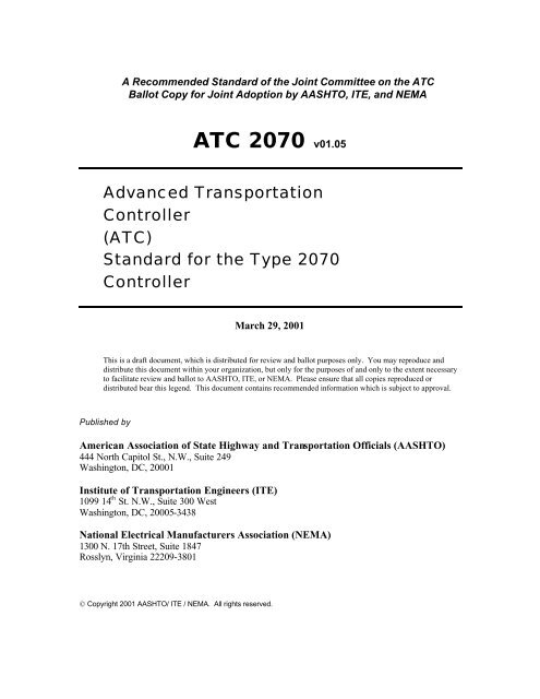
A Recommended Standard <strong>of</strong> the Joint Committee on the ATC<br />
Ballot Copy for Joint Adoption by AASHTO, ITE, and NEMA<br />
ATC 2070 v01.05<br />
Advanced <strong>Transportation</strong><br />
<strong>Controller</strong><br />
(ATC)<br />
Standard for the Type 2070<br />
<strong>Controller</strong><br />
March 29, 2001<br />
This is a draft document, which is distributed for review and ballot purposes only. You may reproduce and<br />
distribute this document within your organization, but only for the purposes <strong>of</strong> and only to the extent necessary<br />
to facilitate review and ballot to AASHTO, ITE, or NEMA. Please ensure that all copies reproduced or<br />
distributed bear this legend. This document contains recommended information which is subject to approval.<br />
Published by<br />
American Association <strong>of</strong> State Highway and <strong>Transportation</strong> Officials (AASHTO)<br />
444 North Capitol St., N.W., Suite 249<br />
Washington, DC, 20001<br />
<strong>Institute</strong> <strong>of</strong> <strong>Transportation</strong> <strong>Engineers</strong> (ITE)<br />
1099 14 th St. N.W., Suite 300 West<br />
Washington, DC, 20005-3438<br />
National Electrical Manufacturers Association (NEMA)<br />
1300 N. 17th Street, Suite 1847<br />
Rosslyn, Virginia 22209-3801<br />
© Copyright 2001 AASHTO/ ITE / NEMA. All rights reserved.
Joint NEMA, AASHTO, and ITE Copyright<br />
and<br />
Advanced <strong>Transportation</strong> <strong>Controller</strong> (ATC)<br />
Type 2070 <strong>Controller</strong><br />
NOTICE<br />
These materials are delivered "AS IS" without any warranties as to their use or performance.<br />
AASHTO/ITE/NEMA AND THEIR SUPPLIERS DO NOT WARRANT THE PERFORMANCE OR<br />
RESULTS YOU MAY OBTAIN BY USING THESE MATERIALS. AASHTO/ITE/NEMA AND<br />
THEIR SUPPLIERS MAKE NO WARRANTIES, EXPRESSED OR IMPLIED, AS TO NON-<br />
INFRINGEMENT OF THIRD PARTY RIGHTS, MERCHANTABILITY, OR FITNESS FOR ANY<br />
PARTICULAR PURPOSE. IN NO EVENT WILL AASHTO, ITE, OR NEMA OR THEIR<br />
SUPPLIERS BE LIABLE TO YOU OR ANY THIRD PART FOR ANY CLAIM OR FOR ANY<br />
CONSEQUENTIAL, INCIDENTAL, OR SPECIAL DAMAGES, INCLUDING ANY LOST PROFITS<br />
OR LOST SAVINGS, ARISING FROM YOUR REPRODUCTION OR USE OF THESE<br />
MATERIALS. EVEN IF AN AASHTO, ITE, OR NEMA REPRESENTATIVE HAS BEEN ADVISED<br />
OF THE POSSIBILITY OF SUCH DAMAGES. Some states or jurisdictions do not allow the<br />
exclusion or limitation <strong>of</strong> incidental, consequential, or special damages, or exclusion <strong>of</strong> implied<br />
warranties, so the above limitations may not apply to you.<br />
Use <strong>of</strong> these materials do not constitute an endorsement or affiliation by or between AASHTO,<br />
ITE, or NEMA and you, your company, or your products and services.<br />
If you are not willing to accept the foregoing restrictions, you should immediately return these<br />
materials.<br />
ATC is a trademark <strong>of</strong> NEMA/AASHTO/ITE.<br />
Standard for the ATC – Type 2070 March 29, 2001<br />
2
Table <strong>of</strong> Contents<br />
1 FOREWORD...............................................................................................................6<br />
2 INTRODUCTION.......................................................................................................7<br />
2.1 Overview..................................................................................................................7<br />
2.2 <strong>Controller</strong>s................................................................................................................7<br />
2.3 <strong>Controller</strong> Housing...................................................................................................8<br />
2.4 Power Supply...........................................................................................................8<br />
2.5 Front Panel...............................................................................................................8<br />
3 GENERAL ATC REQUIREMENTS........................................................................8<br />
3.1 General.....................................................................................................................8<br />
3.1.1 Interchangeability............................................................................................8<br />
3.1.2 Documentation................................................................................................9<br />
3.1.3 Packaging......................................................................................................10<br />
3.1.4 Delivery.........................................................................................................10<br />
3.1.5 Metals............................................................................................................10<br />
3.1.6 Mechanical Hardware ...................................................................................11<br />
3.1.7 Electrical Isolation........................................................................................11<br />
3.2 Components ...........................................................................................................11<br />
3.2.1 General..........................................................................................................11<br />
3.2.2 Electronic Components.................................................................................11<br />
3.2.3 Capacitors......................................................................................................12<br />
3.2.4 Potentiometers...............................................................................................12<br />
3.2.5 Resistors........................................................................................................13<br />
3.2.6 Semiconductor Devices.................................................................................13<br />
3.2.7 Transformers and Inductors ..........................................................................13<br />
3.2.8 Triacs.............................................................................................................13<br />
3.2.9 Circuit Breakers ............................................................................................14<br />
3.2.10 Fuses..............................................................................................................14<br />
3.2.11 Switches ........................................................................................................14<br />
3.2.12 Terminal Blocks............................................................................................14<br />
3.2.13 Wiring, Cabling, and Harnesses....................................................................15<br />
3.2.14 Indicators and Character Displays ................................................................15<br />
3.2.15 Connectors ....................................................................................................16<br />
3.2.16 Surge Protection Device................................................................................17<br />
3.3 Mechanical Requirements......................................................................................17<br />
3.3.1 Assemblies ....................................................................................................17<br />
3.3.2 PCB Design and Connectors.........................................................................18<br />
3.3.3 Model and Serial Numbers ...........................................................................18<br />
3.3.4 Workmanship................................................................................................18<br />
3.3.5 Tolerances .....................................................................................................18<br />
3.4 Engineering............................................................................................................18<br />
3.4.1 Human Engineering ......................................................................................19<br />
3.4.2 Design Engineering.......................................................................................19<br />
3.4.3 Generated Noise............................................................................................19<br />
3.5 Printed Circuit Boards............................................................................................19<br />
Standard for the ATC – Type 2070 March 29, 2001<br />
3
3.5.1 Design, Fabrication, and Mounting ..............................................................19<br />
3.5.2 Soldering.......................................................................................................21<br />
3.5.3 Definitions.....................................................................................................21<br />
3.6 Quality Control ......................................................................................................21<br />
3.6.1 Components ..................................................................................................21<br />
3.6.2 Subassembly, Unit, or Module......................................................................21<br />
3.6.3 Pre-delivery Repair .......................................................................................21<br />
3.7 Electrical, Environmental, and Testing Requirements ..........................................22<br />
3.7.1 General..........................................................................................................22<br />
3.7.2 Certification ..................................................................................................22<br />
3.7.3 Inspection......................................................................................................22<br />
3.7.4 Environmental and Electrical........................................................................22<br />
3.7.5 Contractor’s Testing Certification................................................................24<br />
4 TYPE 2070 CONTROLLER UNIT.........................................................................25<br />
4.1 General...................................................................................................................25<br />
4.1.1 Module Descriptions.....................................................................................25<br />
4.1.2 Unit Configuration........................................................................................25<br />
4.1.3 Metalwork .....................................................................................................26<br />
4.1.4 Power Limitations.........................................................................................26<br />
4.1.5 EIA-485 Communications Circuitry.............................................................26<br />
4.1.6 EIA-485 Line Drivers/Receivers ..................................................................26<br />
4.1.7 MTBF Analysis Report.................................................................................27<br />
4.1.8 Sockets ..........................................................................................................27<br />
4.1.9 SDLC ............................................................................................................27<br />
4.1.10 Year 2000 Compliance..................................................................................27<br />
4.2 Type 2070-1 CPU Module .....................................................................................27<br />
4.2.1 Type 2070 – 1A Configuration.....................................................................28<br />
4.2.2 Type 2070 – 1B Configuration .....................................................................28<br />
4.2.3 Main <strong>Controller</strong> Board (MCB) .....................................................................29<br />
4.2.4 Transition Board ...........................................................................................31<br />
4.2.5 Shielded Interface Harness............................................................................31<br />
4.2.6 Data Key .......................................................................................................31<br />
4.2.7 CPU Module S<strong>of</strong>tware..................................................................................31<br />
4.3 Type 2070-2 Field I/O Module (FI/O)...................................................................43<br />
4.3.1 Type 2070-2A Module..................................................................................43<br />
4.3.2 Type 2070-2B Module..................................................................................43<br />
4.3.3 Field <strong>Controller</strong> Unit (FCU) .........................................................................43<br />
4.3.4 Parallel I/O Ports...........................................................................................43<br />
4.3.5 Other Module Circuit Functions ...................................................................44<br />
4.3.6 Serial Communications/Logic Circuitry.......................................................45<br />
4.3.7 Buffers...........................................................................................................46<br />
4.3.8 I/O Functions.................................................................................................46<br />
4.3.9 Data Communications Protocols...................................................................49<br />
4.4 Type 2070-3 Front Panel Assembly ......................................................................62<br />
4.4.1 General..........................................................................................................62<br />
4.4.2 Keyboards .....................................................................................................62<br />
Standard for the ATC – Type 2070 March 29, 2001<br />
4
4.4.3 CPU Active Indicator....................................................................................62<br />
4.4.4 Display..........................................................................................................62<br />
4.4.5 FPA <strong>Controller</strong>..............................................................................................63<br />
4.4.6 Electronic Bell...............................................................................................66<br />
4.5 Type 2070-4 Power Supply Module .....................................................................66<br />
4.5.1 General..........................................................................................................66<br />
4.5.2 Module Front.................................................................................................67<br />
4.5.3 Input Protection.............................................................................................67<br />
4.5.4 +5VDC Standby Power.................................................................................67<br />
4.5.5 Monitor Circuitry..........................................................................................67<br />
4.5.6 Power Supply Requirements.........................................................................68<br />
4.6 Unit Chassis and Type 2070-5 VME Cage Assembly...........................................69<br />
4.6.1 General..........................................................................................................69<br />
4.6.2 Serial Motherboard .......................................................................................70<br />
4.6.3 Type 2070-5 VME Cage Assembly..............................................................70<br />
4.6.4 Type 2070-1A CPU Main <strong>Controller</strong> Board.................................................70<br />
4.7 Chapter Details.......................................................................................................71<br />
5 TYPE 2070 PERIPHERAL EQUIPMENT AND NEMA MODULE ..................86<br />
5.1 Type 2070-6 A & B Async/Modem Serial Comm Modules .................................86<br />
5.1.1 Power Requirements .....................................................................................86<br />
5.1.2 Circuitry........................................................................................................86<br />
5.1.3 Modem Requirements...................................................................................86<br />
5.1.4 Logic Switches..............................................................................................87<br />
5.1.5 Control Switch ..............................................................................................87<br />
5.2 Type 2070-7A & 7B Async Serial Comm Module ...............................................88<br />
5.2.1 Circuitry........................................................................................................88<br />
5.2.2 2070 -7A .......................................................................................................88<br />
5.2.3 2070 - 7B.......................................................................................................88<br />
5.2.4 Indicators.......................................................................................................88<br />
5.3 Reserved for Future Use ........................................................................................88<br />
5.4 Type 2070N <strong>Controller</strong> Unit..................................................................................88<br />
5.4.1 General..........................................................................................................88<br />
5.4.2 Type 2070-8 NEMA Interface Module.........................................................89<br />
5.4.3 Type 2070N Back Cover...............................................................................92<br />
5.5 Chapter Details.......................................................................................................92<br />
6 GLOSSARY.............................................................................................................105<br />
6.1.1 Terms and Abbreviations............................................................................105<br />
Standard for the ATC – Type 2070 March 29, 2001<br />
5
1 FOREWORD<br />
The purpose <strong>of</strong> this document is to define the standard for a multi-purpose Advanced<br />
<strong>Transportation</strong> <strong>Controller</strong> (ATC) – Type 2070 <strong>Controller</strong>.<br />
The effort to develop standards for the ATC began with the Federal Highway<br />
Administration gathering together a group <strong>of</strong> users interested in furthering the<br />
development <strong>of</strong> open architecture hardware and s<strong>of</strong>tware to meet the future needs <strong>of</strong><br />
Intelligent <strong>Transportation</strong> Systems. The ATC users group gained the support <strong>of</strong> the<br />
<strong>Institute</strong> <strong>of</strong> <strong>Transportation</strong> <strong>Engineers</strong> to continue their work in developing standards for<br />
the ATC. The American Association <strong>of</strong> State Highway and <strong>Transportation</strong> Officials<br />
(AASHTO) and the National Electrical Manufacturer’s Association joined with ITE to<br />
create a joint effort<br />
In July, 1999, a formal agreement was reached among NEMA, ITE and AASHTO to<br />
jointly develop, approve and maintain the ATC standards. Under the guidance <strong>of</strong> a Joint<br />
AASHTO/ITE/NEMA Committee on the ATC, a Working Group was created in order to<br />
develop a standard for the Advanced <strong>Transportation</strong> <strong>Controller</strong>. The first <strong>of</strong>ficial meeting<br />
<strong>of</strong> this working group was in September,1999.<br />
In preparation <strong>of</strong> this Standards Publication, input <strong>of</strong> users and other interested parties<br />
was sought and evaluated. Inquiries, comments and proposed or recommended revisions<br />
should be submitted to:<br />
Standards Engineer<br />
<strong>Institute</strong> <strong>of</strong> <strong>Transportation</strong> <strong>Engineers</strong><br />
1099 14 th St. NW, Suite 300 West<br />
Washington, DC 20005-3483<br />
voice: 202-298-0222<br />
fax: 202-298-7722<br />
email: jcheeks@ite.org<br />
Standard for the ATC – Type 2070 March 29, 2001<br />
6
2 INTRODUCTION<br />
2.1 Overview<br />
The Advanced <strong>Transportation</strong> <strong>Controller</strong> (ATC) is a general purpose field computer that<br />
is intended for continuous unattended operation in harsh environments. The Type 2070<br />
ATC defined in this standard is intended to be the first <strong>of</strong> what may be a family <strong>of</strong><br />
advanced transportation control devices.<br />
This standard defines specific, interchangeable modules that are combined to form a<br />
Type 2070 ATC that is capable <strong>of</strong> running control s<strong>of</strong>tware that might be provided from a<br />
variety <strong>of</strong> providers. These specifications, in many cases, define several module options<br />
that can be arranged in a variety <strong>of</strong> composition configurations to meet the needs <strong>of</strong> the<br />
user.<br />
In order to effectively use this standard, the procuring AGENCY should define the<br />
composition configuration that is intended to be provided in accordance with this<br />
standard. This standard lay out sample compositions for full, NEMA, Lite, and ITS<br />
configurations.<br />
2.2 <strong>Controller</strong>s<br />
The Type 2070 version <strong>of</strong> the ATC is designed such that all components are fully<br />
standardized and are therefore interchangeable. The<br />
The more general ATC<br />
standard also allows some<br />
latitude for manufacturers<br />
to customize the<br />
packaging. At this<br />
writing, the CPU, or<br />
Engine Board as we are<br />
calling it, are modular and<br />
interchangeable between<br />
manufacturers. Other<br />
components <strong>of</strong> the general<br />
ATC controller unit<br />
standard will not be<br />
required to be<br />
interchangeable between<br />
manufacturers, thus<br />
allowing maximum<br />
packaging flexibility<br />
RAM<br />
EPROM<br />
RTC<br />
DUART<br />
Data Key<br />
Host<br />
Board<br />
External Front Panel<br />
CPU<br />
ATC Engine Board<br />
EIA - 232<br />
(Multiple Ports)<br />
IEEE 802.3<br />
(Ethernet)<br />
Optional<br />
Notebook Computer<br />
which will allow the most cost effective design implementations where needed, as well as<br />
allowing for very small designs where needed for size restricted applications. The<br />
general ATC standard does not preclude other packaging implementations, which may be<br />
Serial I/O<br />
EIA - 485<br />
Fiber Transceiver<br />
Other Device ?<br />
Minimum System Boundry<br />
Power<br />
Supply<br />
Internal<br />
Front Panel<br />
(Optional)<br />
Serial Interface Units<br />
2070 Modem Card<br />
Serial Backplane<br />
(Optional)<br />
Standard for the ATC – Type 2070 March 29, 2001<br />
7
fully modular by function. Key features and modules <strong>of</strong> the controller unit are as<br />
follows.<br />
2.3 <strong>Controller</strong> Housing<br />
The Type 2070 controller defines a controller housing that is intended to fit an EIA 19”<br />
rack mounted form commonly found in the Type 332 family <strong>of</strong> cabinets. A NEMA base<br />
module is defined for those NEMA TS1 and TS2 shelf mounted applications.<br />
2.4 Power Supply<br />
A power supply module is used to convert 120-volt power to voltages required to operate<br />
the electronics inside the Type 2070 controller unit. This power supply must meet certain<br />
minimum electrical characteristics defined herein for its intended use.<br />
This, however, does not preclude a manufacturer or an AGENCY from requiring a<br />
specific power supply form factor so that it is consistent across a wide range <strong>of</strong> packages<br />
that may be employed by that AGENCY.<br />
2.5 Front Panel<br />
The <strong>Controller</strong> Front Panel contains a keyboard and display that comprise the user field<br />
interface. The Front Panel on the Type 2070 controller is optional. Communications to<br />
the controller processor may be over one <strong>of</strong> the serial ports.<br />
The front panel might also be used as a portable input device rather than or in addition to<br />
a notebook PC. This will <strong>of</strong>fer a low cost alternative and will provide a minimum<br />
functionality for those agencies that have trouble purchasing and supporting notebook<br />
PCs.<br />
3 GENERAL ATC REQUIREMENTS<br />
3.1 General<br />
In CASE <strong>of</strong> CONFLICT, the individual chapter shall govern over this chapter.<br />
All furnished equipment shall be new and unused. Vacuum or gaseous tubes and electromechanical<br />
devices (unless specifically called out) shall not be used.<br />
3.1.1 Interchangeability<br />
Assemblies and their associated devices shall be electrically and mechanically<br />
interchangeable at both the assembly and device levels:<br />
ASSEMBLIES<br />
ASSOCIATED DEVICES<br />
Standard for the ATC – Type 2070 March 29, 2001<br />
8
Type 2070 <strong>Controller</strong> Unit<br />
- Type 2070-1 CPU Module<br />
- Type 2070-2A & 2B Field I/O Module<br />
- Type 2070-3 Front Panel Assembly<br />
- Type 2070-4 Power Supply<br />
- Type 2070-5 VME Cage Assembly<br />
- Type 2070-6 Serial Comm Module<br />
- Type 2070-7 Serial Comm Module<br />
Type 2070N <strong>Controller</strong> Unit<br />
- Type 2070 <strong>Controller</strong> Unit<br />
- Type 2070-8 NEMA Module<br />
- Type 2070-2B Field I/O Module<br />
3.1.2 Documentation<br />
3.1.2.1 Manuals<br />
Two copies <strong>of</strong> Manual Documentation shall be supplied for each item purchased up to<br />
200 manuals per order. The manual shall be bound in durable covers made <strong>of</strong> either 65-<br />
pound stock paper or clear plastic. The manual shall be printed on 215.9 mm by 279.4<br />
mm paper, with the exception that schematics, layouts, parts lists and plan details may be<br />
on 279.4 mm by 431.8 mm sheets, with each sheet neatly folded to 215.9 mm by 279.4<br />
mm size. Manual text font shall be HELVETICA BOLD or ARIAL. Text characters<br />
shall be no more than 10 characters per 25.4 mm and 7 lines per 25.4 mm, with the<br />
exception <strong>of</strong> schematic text, which shall be no more than 18 characters per 25.4 mm and<br />
11 lines per 25.4 mm.<br />
3.1.2.2 Manual Contents<br />
Each manual shall include the following sections in the order listed:<br />
1. Table <strong>of</strong> Contents<br />
2. Glossary<br />
3. General Description<br />
4. General Characteristics<br />
5. Installation<br />
6. Adjustments<br />
7. Theory <strong>of</strong> Operation<br />
a. Systems Description (include block diagram).<br />
b. Detailed Description <strong>of</strong> Circuit Operation.<br />
8. Maintenance<br />
a. Preventive Maintenance.<br />
b. Trouble Analysis.<br />
c. Trouble Shooting Sequence Chart.<br />
d. Wave Forms.<br />
e. Voltage Measurements.<br />
Standard for the ATC – Type 2070 March 29, 2001<br />
9
f. Alignment Procedures.<br />
9. Parts List (include circuit and board designation, part type and<br />
class, power rating, component manufacturer, mechanical part<br />
manufacturer, data specification sheets for special design<br />
components and original manufacturer's part number).<br />
10. Electrical Interconnection Details & Drawings.<br />
11. Schematic and Logic Diagram<br />
12. Assembly Drawings and a pictorial diagram showing physical locations and<br />
identification <strong>of</strong> each component or part.<br />
13. The date, serial numbers, model numbers and revision numbers <strong>of</strong> equipment<br />
covered by the manuals shall be printed on the front cover <strong>of</strong> the manuals.<br />
3.1.2.3 Manual Pouches<br />
Deleted<br />
3.1.2.4 Draft Manual<br />
Deleted<br />
3.1.3 Packaging<br />
Each item delivered shall be individually packed in its own shipping container. When<br />
loose Styr<strong>of</strong>oam is used for packing the item, the item shall be sealed in a plastic bag to<br />
prevent direct contact with the Styr<strong>of</strong>oam.<br />
3.1.4 Delivery<br />
Each item delivered for testing shall be complete, including manuals, and ready for<br />
testing.<br />
3.1.5 Metals<br />
All sharp edges and corners shall be rounded and free <strong>of</strong> any burrs.<br />
3.1.5.1 Aluminum<br />
Sheet shall be 1.524 mm (0.060-inch) minimum thick Type 3003-H14 or Type 5052-H32<br />
ASTM Designation B209 aluminum alloy. Rod, Bar and Extruded shall be Type 6061-<br />
T6, or equal.<br />
3.1.5.2 Stainless Steel<br />
Sheet shall be annealed or one-quarter-hard complying with the ASTM Designation:<br />
A666 for Type 304, Grades A or B, stainless steel sheet.<br />
Standard for the ATC – Type 2070 March 29, 2001<br />
10
3.1.5.3 Cold Rolled Steel<br />
Sheet, Rod, Bar and Extruded shall be Type 1018/1020.<br />
3.1.5.3.1 Plating<br />
All cold roll steel shall be plated. All plating shall be either cadmium plating meeting the<br />
requirements <strong>of</strong> Federal Specification QQ-P-416C, Type 2 Class l or zinc plating meeting<br />
the requirements <strong>of</strong> ASTM B633-85 Type II SC4.<br />
3.1.6 Mechanical Hardware<br />
All bolts, nuts, washers, screws (size 8 or larger), hinges and hinge pins shall be stainless<br />
steel unless otherwise specified.<br />
3.1.7 Electrical Isolation<br />
Within the circuit <strong>of</strong> any device, module, or PCB, electrical isolation shall be provided<br />
between DC logic ground, equipment ground and the AC grounded conductor. They shall<br />
be electrically isolated from each other by 500 megohms, minimum, when tested at the<br />
input terminals with 500 VDC.<br />
3.2 Components<br />
3.2.1 General<br />
All components shall be second sourced and shall be <strong>of</strong> such design, fabrication,<br />
nomenclature or other identification as to be purchased from a wholesale distributor or<br />
from the component manufacturer, except as follows:<br />
3.2.1.1<br />
When a component is <strong>of</strong> such special design that it precludes the purchase <strong>of</strong> identical<br />
components from any wholesale distributor or component manufacturer, one spare<br />
duplicate component shall be furnished with each 20, or fraction there<strong>of</strong>, components<br />
used.<br />
3.2.1.2<br />
The electronic circuit design shall be such that all components <strong>of</strong> the same generic type,<br />
regardless <strong>of</strong> manufacturer, shall function equally in accordance with the specifications.<br />
3.2.2 Electronic Components<br />
Standard for the ATC – Type 2070 March 29, 2001<br />
11
3.2.2.1<br />
No device shall be socket mounted unless specifically called out.<br />
3.2.2.2<br />
No component shall be operated above 80% <strong>of</strong> its maximum rated voltage, current or<br />
power ratings. Digital components shall not be operated above 3% over their nominal<br />
voltage, current or power ratings.<br />
3.2.2.3<br />
No component shall be provided where the manufactured date is 3 years older than the<br />
contract award date. The design life <strong>of</strong> all components, operating for 24 hours a day and<br />
operating in their circuit application, shall be 10 years or longer.<br />
3.2.2.4<br />
Encapsulation <strong>of</strong> 2 or more discrete components into circuit modules is prohibited except<br />
for transient suppression circuits, resistor networks, diode arrays, solid- state switches,<br />
optical isolators and transistor arrays. Components shall be arranged so they are easily<br />
accessible, replaceable and identifiable for testing and maintenance. Where damage by<br />
shock or vibration exists, the component shall be supported mechanically by a clamp,<br />
fastener, retainer, or hold-down bracket.<br />
3.2.2.5<br />
The Contractor shall submit detailed engineering technical data on all components at the<br />
request <strong>of</strong> the AGENCY. A letter from the component manufacturer shall be submitted<br />
with the detailed engineering data when the proposed application <strong>of</strong> the component alters<br />
the technical data. The letter shall certify that the component application meets the<br />
requirements <strong>of</strong> this standard.<br />
3.2.3 Capacitors<br />
The DC and AC voltage ratings as well as the dissipation factor <strong>of</strong> a capacitor shall<br />
exceed the worst-case design parameters <strong>of</strong> the circuitry by 150%. Capacitor<br />
encasements shall be resistant to cracking, peeling and discoloration. All capacitors shall<br />
be insulated and shall be marked with their capacitance values and working voltages.<br />
Electrolytic capacitors shall not be used for capacitance values <strong>of</strong> less than 1.0 micr<strong>of</strong>arad<br />
and shall be marked with polarity.<br />
3.2.4 Potentiometers<br />
Potentiometers with ratings from 1 to 2 watts shall meet Military Type RV4<br />
requirements. Under 1 Watt potentiometers shall be used only for trimmer type function.<br />
Standard for the ATC – Type 2070 March 29, 2001<br />
12
The potentiometer power rating shall be at least 100% greater than the maximum power<br />
requirements <strong>of</strong> the circuit.<br />
3.2.5 Resistors<br />
Fixed carbon film, deposited carbon, or composition insulated resistors shall conform to<br />
the performance requirements <strong>of</strong> Military Specifications MIL-R-11F or MIL-R-22684.<br />
All resistors shall be insulated and shall be marked with their resistance values.<br />
Resistance values shall be indicated by the EIA color codes, or stamped value. The value<br />
<strong>of</strong> the resistors shall not vary by more than 5% between -37 degrees C and 74 degrees C<br />
Special ventilation or heat sinking shall be provided for all 2- watt or greater resistors.<br />
They shall be insulated from the PCB.<br />
3.2.6 Semiconductor Devices<br />
3.2.6.1<br />
All solid-state devices, except LED's, shall be <strong>of</strong> the silicon type.<br />
3.2.6.2<br />
All transistors, integrated circuits, and diodes shall be a standard type listed by EIA and<br />
clearly identifiable.<br />
3.2.6.3<br />
All metal oxide semiconductor components shall contain circuitry to protect their inputs<br />
and outputs against damage due to high static voltages or electrical fields.<br />
3.2.6.4<br />
Device pin "1" locations shall be properly marked on the PCB adjacent to the pin.<br />
3.2.7 Transformers and Inductors<br />
All power transformers and inductors shall have the manufacturer's name or logo and part<br />
number clearly and legibly printed on the case or lamination.<br />
All transformers and inductors shall have their windings insulated, shall be protected to<br />
exclude moisture, and their leads color coded with an approved EIA color code or<br />
identified in a manner to facilitate proper installation.<br />
3.2.8 Triacs<br />
Each triac with a designed circuit load <strong>of</strong> greater than 0.5 Amperes at 120 VAC shall be<br />
mounted to a heat sink with a machine screw and nut with integral lockwasher.<br />
Standard for the ATC – Type 2070 March 29, 2001<br />
13
3.2.9 Circuit Breakers<br />
Circuit breakers shall be listed by UL or ETL. The trip and frame sizes shall be plainly<br />
marked (marked on the breaker by the manufacturer), and the ampere rating shall be<br />
visible from the front <strong>of</strong> the breaker. Contacts shall be silver alloy and enclosed in an arc<br />
quenching chamber. Overload tripping shall not be influenced by an ambient air<br />
temperature range <strong>of</strong> from -18 degrees C to 50 degrees C. The minimum Interrupting<br />
Capacity shall be 5,000 Amperes, RMS when the breaker is secondary to a UL approved<br />
fuse or primary circuit breaker and both breakers in concert provide the rated capacity.<br />
For circuit breakers 80 amperes and above, the minimum interrupting capacity shall be<br />
10,000 amperes, RMS. Circuit breakers shall be the trip-free type with medium trip<br />
delay characteristic (Carlingswitch Time Delay Curve #24 or equal).<br />
3.2.10 Fuses<br />
All FUSEs shall be 3AG Slow Blow type and resident in a holder. Fuse size rating shall<br />
be labeled on the holder or on the panel adjacent to the holder. Fuses shall be easily<br />
accessible and removable without use <strong>of</strong> tools.<br />
3.2.11 Switches<br />
3.2.11.1 Logic<br />
The switch contacts shall be rated for a minimum <strong>of</strong> one ampere resistive load at 120<br />
VAC and shall be silver over brass (or equal). The switch shall be rated for a minimum<br />
<strong>of</strong> 40,000 operations.<br />
3.2.11.2 Control<br />
The switch contacts shall be rated for a minimum <strong>of</strong> five ampere resistive load at 120<br />
VAC or 28 VDC and shall be gold over brass (or equal). The switch shall be rated for a<br />
minimum <strong>of</strong> 40,000 operations.<br />
3.2.11.3 Power<br />
Ratings shall be the same as CONTROL, except the contact rating shall be a minimum <strong>of</strong><br />
ten amperes at 125 VAC.<br />
3.2.12 Terminal Blocks<br />
The terminal blocks shall be barrier type, rated at 20 amperes and 600 VAC RMS<br />
minimum. The terminal screws shall be 7.938 mm minimum length nickel plated brass<br />
binder head type with screw inserts <strong>of</strong> the same material. Screw size is called out under<br />
the associated file, panel or assembly.<br />
Standard for the ATC – Type 2070 March 29, 2001<br />
14
3.2.13 Wiring, Cabling, and Harnesses<br />
3.2.13.1<br />
Harnesses shall be neat, firm and properly bundled with external protection. They shall<br />
be tie-wrapped and routed to minimize crosstalk and electrical interference. Each harness<br />
shall be <strong>of</strong> adequate length to allow any conductor to be connected properly to its<br />
associated connector or termination point. Conductors within an encased harness have no<br />
color requirements.<br />
3.2.13.2<br />
Wiring containing AC shall be bundled separately or shielded separately from all DC<br />
logic voltage control circuits.<br />
3.2.13.3<br />
Wiring shall be routed to prevent conductors from being in contact with metal edges.<br />
Wiring shall be arranged so that any removable assembly may be removed without<br />
disturbing conductors not associated with that assembly.<br />
3.2.13.4<br />
All conductors shall conform to MIL-W-16878E/1 or better and shall have a minimum <strong>of</strong><br />
19 strands <strong>of</strong> copper. The insulation shall be polyvinyl chloride with a minimum<br />
thickness <strong>of</strong> 10 mils or greater. Where insulation thickness is 15 mils or less, the<br />
conductor shall conform to MIL-W-16878/17.<br />
3.2.13.5<br />
Conductor color identification shall be as follows:<br />
Grounded AC circuits - gray or white<br />
Equip. Ground - solid green or continuous green color with 1 or more yellow<br />
stripes.<br />
DC logic ground - continuous white with a red stripe.<br />
Ungrounded AC+ - continuous black or black with colored stripe.<br />
DC logic ungrounded or signal - any color not specified<br />
3.2.14 Indicators and Character Displays<br />
All indicators and character displays shall be readily visible at a radius <strong>of</strong> up to 1.2 m (4<br />
feet) within the cone <strong>of</strong> visibility when the indicator is subjected to 97,000 lux (9,000<br />
foot-candles) <strong>of</strong> white light with the light source at 45 +/-2 degrees to the front panel.<br />
Standard for the ATC – Type 2070 March 29, 2001<br />
15
3.2.14.1<br />
3.2.14.2 Indicators<br />
All indicators and character displays shall have a minimum 90 degrees cone <strong>of</strong> visibility<br />
with its axis perpendicular to the panel on which the indicator is mounted. All indicators<br />
shall be self-luminous. All indicators shall have a rated life <strong>of</strong> 100,000 hours minimum.<br />
Each LED indicator shall be white or clear when <strong>of</strong>f and red when on. Indicators<br />
supplied on equipment requiring handles shall be mounted such that a horizontal<br />
clearance shall be provided.<br />
3.2.14.3 Character Displays<br />
Liquid Crystal Displays (LCD) shall be readable at temperatures <strong>of</strong> -20 degrees C to +74<br />
degrees C. All controller unit functions are required to operate at temperatures <strong>of</strong> –37<br />
degrees C to +74 degrees C.<br />
3.2.15 Connectors<br />
3.2.15.1 General<br />
Connectors shall be keyed to prevent improper insertion <strong>of</strong> the wrong connector where<br />
equipment damage or operator injury may result. The mating connectors shall be<br />
designated as the connector number and male/female relationship, such as C1P (plug or<br />
PCB edge connector) and C1S (socket).<br />
3.2.15.2 Type T<br />
Type T connector shall be a single row, 10 position, feed through terminal block. The<br />
terminal block shall be a barrier type with 6-32, 6.35 mm or longer, nickel plated brass<br />
binder head screws. Each terminal shall be permanently identified as to its function.<br />
3.2.15.3 Type M<br />
Pin and socket contacts for connectors shall be beryllium copper construction subplated<br />
with 0.00127 mm nickel and plated with 0.00076 mm gold. Pin diameter shall be 1.57<br />
mm. All pin and socket connectors shall use the AMP #601105-1 or #91002-1 contact<br />
insertion tool and the AMP #305183 contact extraction tool.<br />
3.2.15.4 Card Edge and Two -Piece PCB<br />
Edge connectors shall have bifurcated gold-plated contacts. The PCB receptacle<br />
connector shall meet or exceed the following:<br />
Operating Voltage: 600 VAC (RMS)<br />
Current Rating:<br />
5.0 amperes<br />
Insulation Material: Diallyl Phthalate or Thermoplastic<br />
Standard for the ATC – Type 2070 March 29, 2001<br />
16
Insulation Resistance: 5,000 megohms<br />
Contact Material: Copper alloy plated with 0.00127 mm<br />
(0.00005 inch) <strong>of</strong> nickel and 0.000381 mm<br />
(0.000015 inch) <strong>of</strong> gold<br />
Contact Resistance: 0.006 ohm maximum<br />
The two-piece PCB connector shall meet or exceed the DIN 41612. The PCB 22/44<br />
Connector shall have 22 independent contacts per side, dual sided with 3.96 mm (0.156<br />
inch) contact centers.<br />
3.2.15.5 Wire Terminal<br />
Each wire terminal shall be solderless with PVC insulation and a heavy duty short -<br />
locking spade type connector. All terminal connectors shall be crimped using a<br />
Controlled-Cycle type crimping tool.<br />
3.2.15.6 Flat Cable<br />
Each flat cable connector shall be designed for use with 26 AWG cable; shall have dual<br />
cantilevered phosphor bronze contacts plated with 508 nm <strong>of</strong> gold over 1270 nm <strong>of</strong><br />
nickel; and shall have a current rating <strong>of</strong> 1 A minimum and an insulation resistance <strong>of</strong> 5<br />
megohms minimum.<br />
3.2.15.7 PCB Header Post<br />
Each PCB header post shall be 1.0 mm square by 8.7 mm high; shall be mounted on 4.0<br />
mm centers; and shall be tempered hard brass plated with 381 nm <strong>of</strong> gold over 1.270 mm<br />
<strong>of</strong> nickel.<br />
3.2.15.8 PCB Header Socket<br />
Each PCB header socket block shall be nylon or diallyl phthalate. Each PCB header<br />
socket contact shall be removable, but crimp-connected to its conductor. The Contractor<br />
shall list the part number <strong>of</strong> the extraction tool recommended by its manufacturer. Each<br />
PCB header socket contact shall be brass or phosphor bronze plated with 562 nm <strong>of</strong> gold<br />
over 1270 nm <strong>of</strong> nickel.<br />
3.2.16 Surge Protection Device<br />
Deleted<br />
3.3 Mechanical Requirements<br />
3.3.1 Assemblies<br />
All assemblies shall be modular, easily replaceable and incorporate plug-in capability for<br />
their associated devices or PCBs. Assemblies shall be provided with 2 guides for each<br />
Standard for the ATC – Type 2070 March 29, 2001<br />
17
plug-in PCB or associated device (except relays). The guides shall extend to within<br />
19.05 mm from the face <strong>of</strong> either the socket or connector and front edge <strong>of</strong> the assembly.<br />
If Nylon guides are used, the guides shall be securely attached to the file or assembly<br />
chassis. All screw type fasteners shall utilize locking devices or locking compounds<br />
except for finger screws, which shall be captive.<br />
3.3.2 PCB Design and Connectors<br />
No components, traces, brackets or obstructions shall be within 3.175 mm <strong>of</strong> the board<br />
edge (guide edges). The manufacturer's name or logo, model number, serial number, and<br />
circuit issue or revision number shall appear and be readily visible on all PCBS. Devices<br />
to prevent PC Board from backing out <strong>of</strong> their assembly connectors shall be provided. All<br />
PCB connectors mounted on a motherboard shall be mechanically secured to the chassis<br />
or frame <strong>of</strong> the unit or assembly.<br />
3.3.3 Model and Serial Numbers<br />
3.3.3.1<br />
The manufacturer's model number, and circuit issue or revision number shall appear on<br />
the rear panel <strong>of</strong> all equipment supplied (where such panel exists). In addition to any<br />
assignment <strong>of</strong> model numbers by the manufacturer, the TYPE number shall be displayed<br />
on the front panel in bold type, at least 6.35 mm high.<br />
3.3.3.2<br />
A permanent label shall be affixed to the inside near and center floor <strong>of</strong> the Type 2070<br />
unit chassis when viewed from the front. The label shall display the unit's serial number.<br />
The number shall be permanent and easy to read.<br />
3.3.4 Workmanship<br />
Workmanship shall conform to the requirements <strong>of</strong> this specification and be in<br />
accordance with the highest industry standards.<br />
3.3.5 Tolerances<br />
The following tolerances shall apply, except as specifically shown on the plans or in<br />
these specifications:<br />
Sheet Metal +/- 1.334 mm (0.0525 inch)<br />
PCB<br />
+0, - 0.254 mm (0.010 inch)<br />
Edge Guides +/- 0.381 mm (0.015 inch)<br />
3.4 Engineering<br />
Standard for the ATC – Type 2070 March 29, 2001<br />
18
The equipment shall be engineered for simplicity, ease <strong>of</strong> operation and maintenance.<br />
3.4.1 Human Engineering<br />
PCBs shall slide smoothly in their guides while being inserted into or removed from the<br />
frame and shall fit snugly into the plug-in PCB connectors. PCBs shall require a force no<br />
less than 22.24 N or greater than 222.4 N for insertion or removal.<br />
3.4.2 Design Engineering<br />
The design shall be inherently temperature compensated to prevent abnormal operation.<br />
The circuit design shall include such compensation as is necessary to overcome adverse<br />
effects due to temperature in the specified environmental range. Personnel shall be<br />
protected from all dangerous voltages.<br />
3.4.3 Generated Noise<br />
No item, component or subassembly shall emit an audible noise level exceeding the peak<br />
level <strong>of</strong> 55 dBa when measured at a distance <strong>of</strong> one meter away from its surface, except<br />
as otherwise noted. No item, component or subassembly shall emit a noise level<br />
sufficient to interfere with processing and communication functions <strong>of</strong> the controller<br />
circuits.<br />
3.5 Printed Circuit Boards<br />
3.5.1 Design, Fabrication, and Mounting<br />
3.5.1.1<br />
All contacts on PCBs shall be plated with a minimum thickness <strong>of</strong> 0.000763 mm gold<br />
over a minimum thickness <strong>of</strong> 0.001905 mm nickel.<br />
3.5.1.2<br />
PCB design shall be such that when a component is removed and replaced, no damage is<br />
done to the board, other components, conductive traces or tracks.<br />
3.5.1.3<br />
Fabrication <strong>of</strong> PCBs shall be in compliance with Military Specification MIL-P-13949,<br />
except as follows:<br />
3.5.1.3.1<br />
NEMA FR-4 glass cloth base epoxy resin copper clad laminates 1.590 mm minimum<br />
thickness shall be used. Inter-component wiring shall be by laminated copper clad track<br />
Standard for the ATC – Type 2070 March 29, 2001<br />
19
having a minimum weight <strong>of</strong> 0.556 kilogram per square meter with adequate cross<br />
section for current to be carried. All copper tracks shall be plated or soldered to provide<br />
complete coverage <strong>of</strong> all exposed copper tracks. Jumper wires to external PCB<br />
components shall be from plated-through padded holes and as short as possible.<br />
3.5.1.3.2<br />
In Section 3.3 <strong>of</strong> Military Specification MIL-P-13949G Grade <strong>of</strong> Pits and Dents shall be<br />
<strong>of</strong> Grade B quality (3.5.1.3) or better. Class <strong>of</strong> permissible bow or twist shall be Class C<br />
(Table V) or better. Class <strong>of</strong> permissible warp or twist shall be Class A (Table II) or<br />
better.<br />
3.5.1.3.3<br />
Sections 4.2 through 6.6 <strong>of</strong> Military Specification MIL-P-13949G (inclusive) shall be<br />
omitted except as referenced in previous sections <strong>of</strong> this specification.<br />
3.5.1.4<br />
The mounting <strong>of</strong> parts and assemblies on the PCB shall conform to Military Specification<br />
MIL-STD-275E, except as follows:<br />
3.5.1.4.1<br />
Semiconductor devices that dissipate more than 250 mW or cause a temperature rise <strong>of</strong><br />
10 degrees C or more shall be mounted with spacers, transipads or heat sinks to prevent<br />
contact with the PCB.<br />
3.5.1.4.2<br />
When completed, all residual flux shall be removed from the PCB.<br />
3.5.1.4.3<br />
The resistance between any 2 isolated, independent conductor paths shall be at least 100<br />
megohms when a 500 VDC potential is applied.<br />
3.5.1.4.4<br />
All PCBs shall be coated with a moisture resistant coating.<br />
3.5.1.4.5<br />
Where less than 6.35 mm lateral separation is provided between the PCB (or the<br />
components <strong>of</strong> a PCB) and any metal surface, a 0.79375 +/-0.39624 mm Thick Mylar<br />
(polyester) plastic cover shall be provided on the metal to protect the PCB.<br />
Standard for the ATC – Type 2070 March 29, 2001<br />
20
3.5.1.5<br />
Each PCB connector edge shall be chamfered at 30 degrees from board side planes. The<br />
key slots shall also be chamfered so that the connector keys are not extracted upon<br />
removal <strong>of</strong> board or jammed upon insertion. The key slots shall be 1.143 +/- 0.127 mm<br />
for 2.54 mm spacing and 1.40 +/- 0.127 mm for 3.96 mm spacing.<br />
3.5.2 Soldering<br />
Hand soldering shall comply with Military Specification MIL-STD-2000.<br />
Automatic flow soldering shall be a constant speed conveyor system with the conveyor<br />
speed set at optimum to minimize solder peaks or points. Temperature shall be controlled<br />
to within +/- 8 degrees C <strong>of</strong> the optimum temperature. The soldering process shall result<br />
in the complete coverage <strong>of</strong> all copper runs, joints and terminals with solder except that<br />
which is covered by an electroplating process. Wherever clinching is not used, a method<br />
<strong>of</strong> holding the components in the proper position for the flow process shall be provided.<br />
If exposure to the temperature bath is <strong>of</strong> such a time-temperature duration, as to come<br />
within 80% <strong>of</strong> any component's maximum specified time-temperature exposure, that<br />
component shall be hand soldered to the PCB after the flow process has been completed.<br />
3.5.3 Definitions<br />
Definitions for the purpose <strong>of</strong> this section on PCBs shall be taken from MIL-P-55110D<br />
Section 3.3 and any current addendum.<br />
3.6 Quality Control<br />
3.6.1 Components<br />
All components shall be lot sampled to assure a consistent high conformance standard to<br />
the design specification <strong>of</strong> the equipment.<br />
3.6.2 Subassembly, Unit, or Module<br />
Complete electrical, environmental and timing compliance testing shall be performed on<br />
each module, unit, printed circuit or subassembly. Components will be tested as a<br />
complete controller assembly. Housing, chassis, and connection terminals shall be<br />
inspected for mechanical sturdiness, and harnessing to sockets shall be electrically tested<br />
for proper wiring sequence. The equipment shall be visually and physically inspected to<br />
assure proper placement, mounting, and compatibility <strong>of</strong> subassemblies.<br />
3.6.3 Pre-delivery Repair<br />
3.6.3.1<br />
Standard for the ATC – Type 2070 March 29, 2001<br />
21
Any defects or deficiencies found by the inspection system involving mechanical<br />
structure or wiring shall be returned through the manufacturing process or special repair<br />
process for correction.<br />
3.6.3.2<br />
PCB flow soldering is allowed a second time if copper runs and joints are not<br />
satisfactorily coated on the first run. Under no circumstances shall a PCB be flow<br />
soldered more than twice.<br />
3.6.3.3<br />
Hand soldering is allowed for printed circuit repair.<br />
3.7 Electrical, Environmental, and Testing Requirements<br />
3.7.1 General<br />
The requirements called out in this standard dealing with equipment evaluation are a<br />
minimum guide and shall not limit the testing and inspection to insure compliance.<br />
3.7.2 Certification<br />
These test procedures shall be followed by the Contractor who shall certify that they have<br />
conducted inspection and testing in accordance with this standard, for all items supplied.<br />
3.7.3 Inspection<br />
A visual and physical inspection shall include mechanical, dimensional and assembly<br />
conformance to all parts <strong>of</strong> this standard.<br />
3.7.4 Environmental and Electrical<br />
All components shall properly operate within the following limits unless otherwise noted:<br />
3.7.4.1<br />
Applied Line Voltage: 90 to 135 VAC, note “Power Failure / Restoration” limits<br />
Frequency: 60 (+/-3.0) Hertz<br />
Humidity: 5 to 95 percent<br />
Ambient Temperature: -37 degrees C to +74 degrees C<br />
Shock - Test per Specification MIL-STD-810E Method 516.4.<br />
Vibration - per Specification MIL-STD-810E Method 514.4, equipment class G.<br />
Standard for the ATC – Type 2070 March 29, 2001<br />
22
All circuits, unless otherwise noted, shall commence operation at or below 90 VAC as the<br />
applied voltage is raised from 50 to 90 VAC at a rate <strong>of</strong> 2 (+/-0.5) volts / second.<br />
3.7.4.2<br />
All equipment shall be unaffected by transient voltages normally experienced on<br />
commercial power lines, as further defined herein. Where applicable, equipment<br />
purchased separately from the cabinet (which it normally is resident) will be tested for<br />
compliance in an AGENCY accepted cabinet connected to the commercial power lines.<br />
3.7.4.3<br />
Deleted<br />
3.7.4.4<br />
The equipment shall withstand (nondestructive) and operate normally when one<br />
discharge pulse <strong>of</strong> plus or minus 300 volts is synchronously added to its incoming AC<br />
power line and moved uniformly over the full wave across 360 degrees or stay at any<br />
point <strong>of</strong> Line Cycle once every second. Peak noise power shall be 5 kilowatts with a<br />
pulse rise time <strong>of</strong> 500 ns. The unit under test will be operated at 20 degrees (+/-5<br />
degrees) C and at 120 (+/-12) VAC.<br />
3.7.4.5<br />
The controller unit communications modules shall be tested resident in an AGENCYaccepted<br />
controller unit which, in turn, is housed in the cabinet.<br />
3.7.4.6<br />
Equipment shall comply only with the requirements <strong>of</strong> UL Bulletin <strong>of</strong> Research No. 23,<br />
"Rain Tests <strong>of</strong> Electrical Equipment."<br />
3.7.4.7<br />
All equipment shall continue normal operation when subjected to the following:<br />
3.7.4.7.1 Low Temperature Test<br />
With the item functioning at a line voltage <strong>of</strong> 90 VAC in its intended operation, the<br />
ambient temperature shall be lowered from 20 degrees C to -37 degrees C at a rate <strong>of</strong> not<br />
more than 18 degrees C per hour. The item shall be cycled at -37 degrees C for a<br />
minimum <strong>of</strong> 5 hours and then returned to 20 degrees C at the same rate. The test shall be<br />
repeated with the line voltage at 135 VAC.<br />
Standard for the ATC – Type 2070 March 29, 2001<br />
23
3.7.4.7.2 High Temperature Test<br />
With the item functioning at a line voltage <strong>of</strong> 90 VAC in its intended operation, the<br />
ambient temperature shall be raised from 20 degrees C to 74 degrees C at a rate <strong>of</strong> not<br />
more than 18 degrees C per hour. The item shall be cycled at 74 degrees C for 5 hours<br />
and then returned to 20 degrees C at the same rate. The test shall be repeated with the<br />
line voltage at 135 VAC.<br />
3.7.4.7.3<br />
All equipment shall resume normal operation following a period <strong>of</strong> at least 5 hours at -37<br />
degrees C and less than 10 percent humidity and at least 5 hours at 74 degrees C and 22<br />
percent humidity, when 90VAC is applied to the incoming AC.<br />
3.7.4.8<br />
The relative humidity and ambient temperature values in the following table shall not be<br />
exceeded.<br />
AMBIENT TEMPERATURE VERSUS RELATIVE HUMIDITY<br />
AT BAROMETRIC PRESSURES (29.92 In. Hg.)<br />
Ambient Temperature/<br />
Dry Bulb (in degrees C)<br />
3.7.4.9<br />
Relative Humidity<br />
(in percent)<br />
Ambient Temperature/<br />
Wet Bulb (in degrees C)<br />
-37.0 to 1.1 10 -17.2 to 42.7<br />
1.1 to 46.0 95 42.7<br />
48.8 70 42.7<br />
54.4 50 42.7<br />
60.0 38 42.7<br />
65.4 28 42.7<br />
71.2 21 42.7<br />
74.0 18 42.7<br />
All equipment shall be capable <strong>of</strong> normal operation following opening and closing <strong>of</strong><br />
contacts (at a 50% duty cycle) in series with the required applied voltage at a rate <strong>of</strong> 30<br />
openings and closings per minute for a period <strong>of</strong> 2 minutes in duration.<br />
3.7.5 Contractor’s Testing Certification<br />
3.7.5.1<br />
A complete QC / final test report shall be supplied with each item. The test report shall<br />
indicate the name <strong>of</strong> the tester and shall be signed by a responsible manager.<br />
Standard for the ATC – Type 2070 March 29, 2001<br />
24
3.7.5.2<br />
The quality control procedure and test report format shall be supplied to the AGENCY<br />
for approval upon request. The quality control procedure shall include the following, in<br />
the order shown:<br />
Acceptance testing <strong>of</strong> all supplied components.<br />
Physical and functional testing <strong>of</strong> all modules and items.<br />
A minimum 100-hour burn-in <strong>of</strong> all equipment.<br />
Physical and functional testing <strong>of</strong> all modules.<br />
4 TYPE 2070 CONTROLLER UNIT<br />
4.1 General<br />
4.1.1 Module Descriptions<br />
The <strong>Controller</strong> Unit shall be composed <strong>of</strong> the Type 2070 Unit Chassis, along with other<br />
modules and assemblies. The following is a list <strong>of</strong> composition deliverables associated to<br />
a number:<br />
NUMBER ITEM DESCRIPTION<br />
1 TYPE 2070 UNIT CHASSIS<br />
2 TYPE 2070-1A CPU MODULE, MULTIPLE BOARD-VME<br />
3 TYPE 2070-1B CPU MODULE, SINGLE BOARD- SERIAL HUB<br />
4 TYPE 2070-2A FIELD I/O MODULE (FI/O for 170 Cab)<br />
5 TYPE 2070-2B FIELD I/O MODULE (ITS & NEMA Cab)<br />
6 TYPE 2070-3A FRONT PANEL MODULE (FP), DISPLAY A<br />
7 TYPE 2070-3B FRONT PANEL MODULE (FP), DISPLAY B<br />
8 TYPE 2070-3C FRONT PANEL MODULE (FP), BLANK<br />
9 TYPE 2070-4A POWER SUPPLY MODULE, 10 AMP<br />
10 TYPE 2070-4B POWER SUPPLY MODULE, 3.5 AMP<br />
11 TYPE 2070-5A VME CAGE ASSEMBLY<br />
12 TYPE 2070-5B MCB 1A MOUNTING ASSEMBLY<br />
13 TYPE 2070-8 NEMA INTERFACE MODULE<br />
14 TYPE 2070-9 2070N BACKCOVER<br />
4.1.2 Unit Configuration<br />
The Type 2070 <strong>Controller</strong> Unit Version defines the module composition that shall be<br />
delivered as follows:<br />
UNIT VERSION COMPOSITION DESCRIPTIVE<br />
Standard for the ATC – Type 2070 March 29, 2001<br />
25
2070 UNIT 1+2+4+6+9+11 Full unit mated to 170 cabinet family<br />
2070N UNIT 1+2+5+6+9+11+13+14 Full unit mated to TS1 cabinet<br />
family<br />
2070L UNIT 1+3+4+8+10 LITE Unit mated to 170 cabinet<br />
family<br />
2070LC UNIT 1+3+5+8+10 LITE unit mated to ITS & TS2<br />
cabinet families<br />
2070LCN UNIT 1+3+5+8+10+13+14 LITE unit mated to TS1 cabinet<br />
Family<br />
4.1.2.1<br />
The communications and option modules/assemblies shall be called out separately from<br />
the unit version. The composition weight shall not exceed 11.3 kilograms.<br />
4.1.3 Metalwork<br />
The CHASSIS Enclosure, Internal Structure Supports, Back Plane Mounting Surface,<br />
Module Plates, Cover Plates, Power Supply Enclosure, and Front Panel shall be made <strong>of</strong><br />
1.524 mm minimum aluminum sheet.<br />
4.1.4 Power Limitations<br />
2070 UNIT module / assembly power limitations shall be as follows:<br />
Types +5VDC +12VDC ISO +12VDC ser -12 VDC ser<br />
MCB 750 mA ----- ----- -----<br />
TRANS BD 750 mA ----- ----- -----<br />
2070-2A FI/O 250 mA 750 mA ----- -----<br />
2070-2B FI/O 250 mA 500 mA ----- -----<br />
2070-3A&B FPA 500 mA ----- 50 mA 50 mA<br />
2070-3C FPA 100 mA ----- 50 mA 50 mA<br />
2070-5 VME Cage 5.0 A ----- 200 mA 200 mA<br />
2070-6 All Comm 500 mA ----- 100 mA 100 mA<br />
2070-7 All Comm 250 mA ----- 50 mA 50 mA<br />
4.1.5 EIA-485 Communications Circuitry<br />
All circuitry associated with the EIA-485 Communications links shall be capable <strong>of</strong><br />
reliably passing a minimum <strong>of</strong> 1.0 megabits per second. Isolation circuitry shall be by<br />
opto- or capacitive-coupled isolation technologies.<br />
4.1.6 EIA-485 Line Drivers/Receivers<br />
Standard for the ATC – Type 2070 March 29, 2001<br />
26
The EIA-485 Line Drivers/Receivers shall be socket mounted and shall not draw more<br />
than 35 mA in active state and 20 mA in inactive state. A 100-Ohm Termination Resistor<br />
shall be provided across each Differential Line Receiver Input. The MOTHERBOARD's<br />
control signals (e.g., SP1-RTS) shall be active, or asserted, when the positive terminal<br />
(e.g., SP1-RTS+) is a lower voltage than its corresponding negative terminal (e.g., SP1-<br />
RTS-). A control signal is inactive when its positive terminal voltage is higher than its<br />
negative terminal. Receive and transmit data signals shall be read as a "1" when the<br />
positive terminal's (e.g., SP1-TXD+) voltage is higher than its corresponding negative<br />
terminal (e.g., SP1-TXD-). A data value is "0" when its positive terminal's (e.g., SP1-<br />
TXD+) voltage is lower than its negative terminal (e.g., SP1-TXD-).<br />
4.1.7 MTBF Analysis Report<br />
Deleted<br />
4.1.8 Sockets<br />
Sockets for devices (called out to be socket mounted) shall be "xx" pin AUGAT 500/800<br />
series AG10DPC or equal.<br />
4.1.9 SDLC<br />
SP5and SP3 SDLC frame address assignments (Command/Response) are as follows:<br />
SP5<br />
SP3<br />
CPU 2070-1 = “19” “19”<br />
FI/O 2070-2A & 8 = “20” Not Applicable<br />
CPU Broadcast to all = “127” “255”<br />
All other addresses are reserved by this standard. The SDLC response frame address<br />
shall be the same address as the Command frame it receives.<br />
4.1.10 Year 2000 Compliance<br />
The 2070 UNIT shall comply with the Year 2000 Compliance:<br />
"Year 2000 compliance for Systems is achieved when an application or system products<br />
(including s<strong>of</strong>tware, microcode and microprocessors), programs, files, databases, and<br />
functionality have or create no logical or mathematical inconsistencies when dealing with<br />
dates prior to and beyond 1999. The year 2000 is recognized and processed as a leap<br />
year. The product must also operate accurately in the manner in which it was intended<br />
for date operation without requiring manual intervention."<br />
4.2 Type 2070-1 CPU Module<br />
Standard for the ATC – Type 2070 March 29, 2001<br />
27
4.2.1 Type 2070 – 1A Configuration<br />
The TYPE 2070-1A CPU shall consist <strong>of</strong> the Main <strong>Controller</strong> Board, Transition Board,<br />
Board Interface Harness, and CPU Module S<strong>of</strong>tware.<br />
4.2.2 Type 2070 – 1B Configuration<br />
The TYPE 2070-1B CPU shall be a single board module meeting the 2X WIDE board<br />
requirements. The module shall be furnished normally resident in MOTHERBOARD Slot<br />
A5. The module shall meet all the requirements listed under this section and Chapter<br />
Details 4.7 except for the following:<br />
4.2.2.1<br />
The VME s<strong>of</strong>tware and hardware bus requirements shall not apply nor do the MCB and<br />
Board Interface Harness physical requirements.<br />
4.2.2.2<br />
A Dual SCC Device (asynch / synch) and associated circuitry shall be furnished to<br />
provide two additional system serial ports. The Dual SCC1 shall be assigned to the<br />
System Serial Port SP1 meeting all requirements called out for SP1. The Dual SCC2<br />
shall be assigned as System Serial Port SP8. The SP8 and associated circuitry shall<br />
interface with the MC68360 address and data structure and serially be connected to the<br />
external world via the DB 25 Pin C13S Connector located on the module front panel. The<br />
SP8 shall meet all SP2 Port requirements including EIA 485 Drivers / receivers and<br />
synchronous bps rate <strong>of</strong> 614 Kbps. An internal LOGIC Switch shall be provided to<br />
disconnect SP8 RTS, CTS and DCD ( Pins 5, 6,7,18,19 and 20 ) lines from C13S<br />
connector.<br />
4.2.2.3<br />
The 68360 SCC1 shall be reassigned to ETHERNET (ENET) Network meeting<br />
ETHERNET 10 MBPS IEEE 802.3 (TP) 10 BASE T Standard Requirements, both<br />
hardware and s<strong>of</strong>tware. The four network lines shall be used to route ETHERNET across<br />
the MOTHERBOARD to the “A” Connectors. DC Grounding plane around the network<br />
connectors and lines shall be provided. Network Lines shall be assigned as: Network 1 =<br />
ENET TX+, Network 2 = ENET TX-, Network 3= ENET RX+, and Network 4 = ENET<br />
RX-. In addition, the conditioned ETHERNET shall be brought out on RJ 45 C14S<br />
Connector mounted on the CPU-1B Front Panel. Four LEDs labeled “TX, RX, TX<br />
Collision and TX Status” shall be mounted on the front panel signifying ETHERNET<br />
operational conditions.<br />
4.2.2.4<br />
Standard for the ATC – Type 2070 March 29, 2001<br />
28
The 2070-1B CPU shall not draw more than 1.25 Amperes <strong>of</strong> +5VDC and 500 mA <strong>of</strong><br />
ISO+12 VDC.<br />
4.2.3 Main <strong>Controller</strong> Board (MCB)<br />
4.2.3.1 General<br />
The MCB shall be a 3U VME bus compliant board and contain a system controller, an<br />
A24-D16 interface, a Master & Slave bus interface, a Multilevel VMEbus Arbiter, a<br />
FAIR VMEbus Requester, a system clock driver, and BTO (64).<br />
4.2.3.2 <strong>Controller</strong><br />
The CONTROLLER Device shall be a Motorola MC68360 or equal, clocked at 24.576<br />
MHz minimum. The Fast IRQ Service System is reserved for AGENCY use only. The<br />
Interrupts shall be configured as follows:<br />
Level 7 - VMEbus IRQ7, ACFAIL<br />
Level 6 - VMEbus IRQ6<br />
Level 5 - VMEbus IRQ5, CPU Module Counters / Timers, LINESYNC (auto<br />
vectored), Serial Interface Interrupts<br />
Level 4 - VMEbus IRQ4<br />
Level 3 - VMEbus IRQ3<br />
Level 2 - VMEbus IRQ2<br />
Level 1 - VMEbus IRQ1<br />
4.2.3.3 Memory Address Organization<br />
4.2.3.3.1<br />
8000 0000 - 80FF FFFF STANDARD<br />
9000 0000 - 9000 FFFF SHORT<br />
16 megabytes <strong>of</strong> contiguous address space for each specified memory (DRAM, SRAM<br />
and FLASH) shall be allocated on an even boundary. The SRAM and FLASH memories<br />
shall be accessed through the OS-9 Operating System's RBF Manager, or approved<br />
equivalent. The address <strong>of</strong> each memory block shall be specified by the Contractor and<br />
provided with the documentation.<br />
4.2.3.3.2<br />
When the incoming +5 VDC falls below its operating level, the SRAM shall drop to its<br />
standby state; and the SRAM and TOD Clock shall shift to the +5 VDC Standby Power.<br />
An on-board circuit shall sense the +5 VDC Standby Power and shift to an On-board<br />
CPU Power Source. The CPU On-board Power shall be capable <strong>of</strong> holding the SRAM<br />
and TOD Clock up for 30 days. When the incoming +5 VDC rises to within its operating<br />
Standard for the ATC – Type 2070 March 29, 2001<br />
29
level, the appropriate MCB Circuitry shall shift from standby power to incoming +5<br />
VDC.<br />
4.2.3.4 RAM Memory<br />
A minimum <strong>of</strong> 4 MB <strong>of</strong> DRAM, organized in 32-bit words, shall be provided. A<br />
minimum <strong>of</strong> 512 KB <strong>of</strong> SRAM, organized in 16- or 32-bit words, shall be provided. The<br />
SRAM shall draw no more than 50 µA at +5 VDC in Standby Mode. The time from the<br />
presentation <strong>of</strong> valid RAM address, select lines, and data lines to the RAM device to the<br />
acceptance <strong>of</strong> data by the RAM device shall not exceed 80 ns and shall be less as required<br />
to fulfill zero wait state RAM device write access under all operational conditions.<br />
4.2.3.5 FLASH Memory<br />
A minimum <strong>of</strong> 4 MB <strong>of</strong> FLASH Memory, organized in 16- or 32-bit words, shall be<br />
provided. The MCB shall be equipped with all necessary circuitry for writing to the<br />
FLASH Memory under program control. No more than 1 MB <strong>of</strong> FLASH Memory shall<br />
be used for Boot Image (List) and a minimum <strong>of</strong> 3 MB shall be available for AGENCY<br />
use.<br />
4.2.3.6 Time-<strong>of</strong>-Day Clock<br />
A s<strong>of</strong>tware settable hardware Time-<strong>of</strong>-Day (TOD) clock shall be provided. The Time-<strong>of</strong>-<br />
Day Clock shall be maintained to within + 0.005% at 20 o C (68 o F) and to within + 0.02%<br />
over the specified operating temperature range as compared to Coordinated Universal<br />
Time (WWV) standard for a period <strong>of</strong> thirty days during periods when AC power is not<br />
applied. The clock shall be aligned to a minimum fractional second resolution <strong>of</strong> 10 ms<br />
and shall track seconds, minutes, hours, day <strong>of</strong> month, month, and year.<br />
4.2.3.7 CPU Reset<br />
A s<strong>of</strong>tware-driven CPU RESET signal (Active LOW) shall be provided to reset other<br />
controller systems. The signal output shall be driver capable <strong>of</strong> sinking 30 mA at 30<br />
VDC. Execution <strong>of</strong> the program module “CPURESET” in the boot image shall assert the<br />
CPU RESET signal once.<br />
4.2.3.8 CPU Activity Indicator<br />
An open-collector output, capable <strong>of</strong> sinking 30 mA at 30 VDC, shall be provided to<br />
drive the Front Panel Assembly CPU Activity LED INDICATOR.<br />
4.2.3.9 Tick Timer<br />
The OS-9 Operating System TICK Timer shall be derived from each transition <strong>of</strong><br />
LINESYNC with a tick rate <strong>of</strong> 120 ticks per second.<br />
Standard for the ATC – Type 2070 March 29, 2001<br />
30
4.2.4 Transition Board<br />
A TRANSITION Board (TB) shall be provided to transfer serial communication and<br />
control signals between the MCB and the Interface Master-board. Said signal and<br />
communication lines shall be driven/received <strong>of</strong>f and on the module compliant to EIA-<br />
485. The Transition Board shall provide a 1 K-Ohm pull-up resistor for the A2 & A3<br />
installed lines. If the DC Ground is not present (slot not occupied) at the CPU EIA-485<br />
line drivers/receivers, the drivers/receivers shall be disabled (inactive).<br />
4.2.5 Shielded Interface Harness<br />
A SHIELDED INTERFACE HARNESS shall be provided. It shall include MCB and<br />
Transition Board connectors with strain relief, lock latch, mating connectors, and harness<br />
conductors. A minimum <strong>of</strong> 25 mm <strong>of</strong> slack shall be provided. No power shall be routed<br />
through the harness. The harness shall be 100% covered by an aluminum mylar foil and<br />
an extruded black 0.8 mm PVC jacket or equal.<br />
4.2.6 Data Key<br />
A DATAKEY Receptacle (KC4210, KC4210PCB or equal) with Key (DK1000or equal)<br />
resident shall be provided and mounted on the CPU module front panel ( or the Transition<br />
Board <strong>of</strong> Type 1A). The Black DATAKEY shall be tested, interrogated and all 128<br />
addresses read using S<strong>of</strong>tware Interface. Power shall not be applied to the receptacle if<br />
the key is not present.<br />
4.2.7 CPU Module S<strong>of</strong>tware<br />
The following shall be supplied:<br />
1. Operating System 5. Validation Suite<br />
2. Drivers and Descriptors 6. Deliverables<br />
3. Application Kernel<br />
4. Error Handler<br />
4.2.7.1 Operating System<br />
The CPU Module shall be supplied with Microware Embedded OS-9 Version 3.03 or<br />
later s<strong>of</strong>tware and, in addition, the following:<br />
1. Embedded OS-9 Real Time Kernel<br />
2. Sequential Character File Manager (SCFMAN)<br />
3. Sequential Protocol File Manager (SPFMAN)<br />
4. Pipe File Manager (PIPEMAN)<br />
5. Random Block File Manager (RBFMAN)<br />
6. C Input Output Library (CIO)<br />
Standard for the ATC – Type 2070 March 29, 2001<br />
31
Boot Image shall include the following utility modules:<br />
Break Date Deiniz Devs Free Copy<br />
Dir Tmode Edt List Load Deldir<br />
Dump Del Ident Iniz Irqs Events<br />
Echo Kill Dcheck Cio Link Kermit<br />
Lmm Mdir Mfree Pd Makdir Save<br />
Attr Rename Procs Unlink Sleep Xmode<br />
Shell Build Setime<br />
4.2.7.2 Drivers and Descriptors<br />
4.2.7.2.1<br />
Supplied modules shall be re-entrant, address independent, and shall not contain selfmodifying<br />
code.<br />
4.2.7.2.2<br />
Drivers shall be provided to access the FLASH, SRAM, and DRAM memories through<br />
RBFMAN, or approved equivalent. The following RBFMAN descriptors shall apply:<br />
4.2.7.2.3<br />
/d0 Floppy Diskette Drive Reserved name; no driver required<br />
/f0 FLASH Drive Accessed as RAM disk & OS-9 /dd default<br />
Device<br />
/h0 Hard Disk Drive Reserved name; no drive required<br />
/r0 SRAM Drive Accessed as RAM disk<br />
/r1 Reserved; no driver required<br />
/r2 Temporary DRAM Drive Allows 1 MB <strong>of</strong> DRAM, accessed as RAM<br />
disk; not initialized at boot time<br />
A driver to handle each <strong>of</strong> the four internal timers under the OS-9 Kernel shall be<br />
provided. Access to the MC68360 internal timers shall be provided through the following<br />
device descriptors:<br />
4.2.7.2.3.1<br />
Descriptor names for each timer:<br />
timer1 = access to MC68360's internal timer #1<br />
timer2 = access to MC68360's internal timer #2<br />
timer3 = access to MC68360's internal timer #3<br />
timer4 = access to MC68360's internal timer #4<br />
timer12 = access to MC68360's internal timer #1 & #2 (cascaded)<br />
Standard for the ATC – Type 2070 March 29, 2001<br />
32
timer34 = access to MC68360's internal timer #3 & #4 (cascaded)<br />
4.2.7.2.3.2 Timer descriptor option structure<br />
The driver shall change appropriate functions only and ignore values that do not apply to<br />
a particular timer function. The data structures are as follows:<br />
struct TER /* timer event register */<br />
{<br />
u_int16 reserveTER :14; /* reserved */<br />
u_int16 timerREF :1; /* output Reference Event */<br />
u_int16 timerCAP :1; /* Capture event */<br />
};<br />
struct TMR /* timer mode register */<br />
{<br />
unsigned timerPS :8; /* prescale */<br />
unsigned timerCE :2; /* capture edge/enable interrupts */<br />
unsigned timerOM :1; /* output mode */<br />
unsigned timerORI :1; /* output reference enable */<br />
unsigned timerFRR :1; /* free run or restart */<br />
unsigned timerICLK :2; /* input clock source */<br />
unsigned timerGE :1; /* gate enable */<br />
};<br />
struct TGCR /* timer global configuration register */<br />
{<br />
unsigned reserveTGCR :12; /* reserved */<br />
unsigned timerCAS_GM :1; /* cascade timers / Gate mode */<br />
unsigned timerFRZ :1; /* freeze timer */<br />
unsigned timerSTP :1; /* stop timer */<br />
unsigned timerRST :1; /* reset timer */<br />
};<br />
typedef struct<br />
{<br />
union<br />
{<br />
struct TGCR TGCR; /* timer global configuration register */<br />
unsigned short tgcr;<br />
} uTGCR;<br />
union<br />
{<br />
struct TMR TMR; /* timer mode register */<br />
unsigned short tmr;<br />
Standard for the ATC – Type 2070 March 29, 2001<br />
33
4.2.7.2.3.3<br />
} uTMR;<br />
u_int32 timerTRR; /* timer reference register */<br />
u_int32 timerTCR; /* timer capture register */<br />
union<br />
{<br />
struct TER TER; /* timer event register */<br />
unsigned short ter;<br />
} uTER;<br />
} TTimer_opts;<br />
Standard OS-9 System Calls for the timers:<br />
error_code _os_open(char *timer_desc_name, u_int32 mode, path_id *path);<br />
error_code _os_close(path_id path);<br />
error_code _os_gs_popt(path_id path, u_int32 *size<strong>of</strong>(TTimer_opts), void<br />
*timer_opts);<br />
error_code _os_ss_popt(path_id path, u_int32 *size<strong>of</strong>(TTimer_opts), void<br />
*timer_opts);<br />
error_code _os_write(path_id path, void *timer_value, u_int32<br />
*size<strong>of</strong>(timer_value));<br />
error_code _os_read(path_id path, void *timer_value, u_int32<br />
*size<strong>of</strong>(timer_value));<br />
error_code _os_ss_sendsig(path_id path, signal_code timer_sig);<br />
error_code _os_ss_relea(path_id path);<br />
4.2.7.2.4<br />
The OS-9 System Calls shall provide access to the CPU Datakey and its control through<br />
the following descriptor name and OS-9 functions<br />
Descriptor name:<br />
datakey = CPU Datakey<br />
Function Calls:<br />
error_code_os_open(char*datakey_desc_name, path_id*path);<br />
error_code=E$NotRdy if CPU Datakey is not installed<br />
error_code_os_read(path_id_path, void*control,128);<br />
error_code=E$NotRdy if CPU Datakey is not inserted<br />
error_code_os_close(path_id path);<br />
4.2.7.2.5<br />
Standard for the ATC – Type 2070 March 29, 2001<br />
34
An Async-Communications Serial Device Driver (SDD) shall be provided to<br />
accommodate a communications network (EIA 232). The SDD shall maintain a Transmit<br />
Buffer (1536 bytes minimum) and a Receive Buffer (1536 bytes minimum).<br />
The SDD shall provide six Flow Control Modes (FCM) as described below.<br />
FCM # Description<br />
0) None: This shall be the default SDD FCM. The SDD shall continually<br />
assert the CTS and DCD signals internally. The SDD shall be capable <strong>of</strong><br />
receiving data at all times. Upon a write command, the SDD shall assert<br />
RTS, transmit the data, and de-asserts RTS when data transmission is<br />
completed (Auto RTS Turn-Off Extension parameter shall NOT delay<br />
RTS being de-asserted). When a user program issues the first RTS related<br />
command, the SDD shall switch to Manual FCM.<br />
1) Manual: The SDD shall transmit and receive data regardless <strong>of</strong> RTS,<br />
CTS, and DCD states. The user program shall have absolute control <strong>of</strong> the<br />
RTS state. The SDD shall NOT assert or de-assert RTS. The CTS and<br />
DCD states are set external to the SDD. The user program may query for<br />
CTS and DCD states.<br />
2) Auto-CTS:The SDD shall continually assert the DCD signal internally.<br />
The SDD shall be capable <strong>of</strong> receiving data at all times. The user program<br />
has absolute control <strong>of</strong> the RTS state. The SDD does not assert or deassert<br />
RTS. The CTS state is set external to the SDD. The SDD shall only<br />
transmit data when CTS is asserted.<br />
3) Auto-RTS: The SDD shall continually assert the CTS and DCD signals<br />
internally. The SDD shall be capable <strong>of</strong> receiving data at all times. Upon a<br />
write command, the SDD shall assert RTS, transmit the data, and deasserts<br />
RTS when data transmission is completed. Auto RTS Turn-Off<br />
Extension parameter shall delay RTS being de-asserted after last character.<br />
If the user program asserts RTS, RTS remains asserted until the user<br />
program de-asserts RTS. If user program de-asserts RTS before the<br />
Transmit Buffer is empty, the SDD shall hold RTS asserted until the<br />
Transmit Buffer is empty.<br />
4) Fully Automatic: The SDD shall receive data when DCD is asserted.<br />
Upon a write command, the SDD shall assert RTS, wait for CTS to be<br />
asserted before transmiting data, and de-asserts RTS when data<br />
transmission is completed. Auto RTS Turn-Off Extension parameter shall<br />
delay RTS being de-asserted after last character.<br />
If the user program asserts RTS, RTS remains asserted until the user<br />
program de-asserts RTS. If user program de-asserts RTS before the<br />
Standard for the ATC – Type 2070 March 29, 2001<br />
35
Transmit Buffer is empty, the SDD shall hold RTS asserted until the<br />
Transmit Buffer is empty.<br />
5) Dynamic: The SDD shall continually assert the DCD signal internally.<br />
The SDD shall be capable <strong>of</strong> receiving data at all times. The SDD shall<br />
transmit data when CTS is asserted. The SDD shall assert RTS when the<br />
number <strong>of</strong> characters in the SDD Receive Buffer is below the Low<br />
Watermark parameter level and shall de-asserts RTS when the number <strong>of</strong><br />
characters in the SDD Receive Buffer is above the High Watermark<br />
parameter level.<br />
The serial device driver shall be able to accept user configuration commands to configure<br />
the device driver via OS9_os_ss_size() function call and to accept user request commands<br />
for status <strong>of</strong> serial port from the device driver via OS9_os_gs_size() function call.<br />
The single 32-bit variable passed by_os_ss_size() is defined as follow:<br />
a) Flow Control Code is SS_OFC (0x23):<br />
Bits Description<br />
31-24 Auto RTS turn-<strong>of</strong>f extension count in number <strong>of</strong> characters (range=0-255<br />
default=0).<br />
15 Auto RTS turn-<strong>of</strong>f extension timing (default=0, 0=bps, 1=equivalent 1200 bps).<br />
14-13 14-13 Reserve for Future Use (default=0).<br />
12 Inhibit Change <strong>of</strong> SCC MRBLR for opened path (default =0; 0=NO; 1=inhibit).<br />
11 Inhibit SCC TODR for opened path (default=0; 0=NO; 1=inhibit).<br />
10-8 Flow Control Mode Number (FCM#) (range=0-5).<br />
7-0 Flow Control Code (FCC) =0x23<br />
Note: The RTS turn-<strong>of</strong>f extension can represent a bps rate independent time value rather<br />
a number <strong>of</strong> character times, (higher bps rates are normalized to equivalent 1200 bps<br />
characters) when selected by bit 15=1. Thus, a value <strong>of</strong> 4 represents the time <strong>of</strong> four<br />
characters at 1200 bps even when the actual rate is 9600. If bit 15=0, then an extension<br />
value = 4 represents 4 characters, which at a bps rate <strong>of</strong> 9600 would extend the RTS by<br />
approximately 3.3 ms.<br />
b) Flow Control Code is SS_IFC (0x22):<br />
Bits Description<br />
31-22 Flow Control Mode 5 high water mark value (range=1-1023; default=512).<br />
21-12 Flow Control Mode 5 low water mark value (range=1-1023; default=256).<br />
11 Inhibit DCD activating control (default=0; 0=<strong>of</strong>f; 1=on).<br />
10 DCD flow control is active (default=0; 0=NO; 1=YES, changed by FCM#).<br />
9-8 Reserved for Future Use (default=0).<br />
7-0 Flow Control Code (FCC) = 0X22.<br />
Standard for the ATC – Type 2070 March 29, 2001<br />
36
Note: The inhibit DCD selection has priority over the DCD ON request in the same<br />
access. Therefore, sending 0x00000822 or 0x00000C22 results in DCD inhibit and DCD<br />
Flow Control inactive for all Flow Modes. A new flow control mode number shall set<br />
DCD function to that required in the new mode unless DCD is inhibit is ON.<br />
c) Flow Control Code is SS_Ssig (0x1a):<br />
Bits Description<br />
31-16 A signal number to be sent to calling process when the state <strong>of</strong> a pin is changed.<br />
15-14 Reserved for Future Use (default=0).<br />
13 Ring is asserted (capable hardware only).<br />
12 CTS is de-asserted.<br />
11 CTS is asserted.<br />
10-8 Reserved for Future Use (default=0).<br />
7-0 Flow Control Code (FCC) = 0x1a.<br />
d) Flow Control Code is SS_DCmd (0x0d):<br />
Bits Description<br />
31-15 Reserved for Future Use (default=0).<br />
14 De-assert DTR (capable hardware only).<br />
13 Assert DTR (capable hardware only).<br />
12 De-assert RTS (duplicated function with_os_ss_DsRTS();).<br />
11 Assert RTS (duplicated function with_os_ss_EnRTS();).<br />
10-8 Reserved for Future Use (default=0).<br />
7-0 Flow Control Code (FCC)=0x0d.<br />
The single 32-bit variable returned by_os_gs_size() is defined as follow:<br />
Bits Description<br />
31-16 Current unfilled transmit buffer character count <strong>of</strong> the serial device driver.<br />
15-11 Reserved for Future Use (default=0).<br />
10-8 Current Flow Control Mode Number (FCM#).<br />
7 Reserved for Future Used (default=0).<br />
6 Overrun error – 0=no error; 1=error since the last query.<br />
5 Frame error – 0=no error; 1=error since the last query.<br />
4 Parity error – 0=no error; 1=error since the last query.<br />
3 Ring Indicator input state – 0=de-asserted; 1=asserted (capable hardware only).<br />
2 DSR input state – 0=de-asserted; 1=asserted (capable hardware only).<br />
1 DCD input state – 0=de-asserted; 1=asserted.<br />
0 CTS input state – 0=de-asserted; 1=asserted.<br />
Standard for the ATC – Type 2070 March 29, 2001<br />
37
4.2.7.2.6<br />
The device shall provide four input buffering modes as follows:<br />
1.Line - characters are buffered up to and including a programmable termination<br />
character.<br />
2. Fixed - a fixed specific number <strong>of</strong> characters is buffered by the driver (1 @ 1200bps, 2<br />
@ 2400bps, 4 @ 4800 bps, 8 @ 9600 bps, and 16 @ 19200 bps & above)<br />
3.Timed- characters are buffered until a programmable inter-character time out occurs.<br />
4. Raw – characters are unbuffered and delivered to the task as received.<br />
4.2.7.2.7<br />
Line, Fixed, and Timed Modes shall be capable <strong>of</strong> being used together. Raw mode shall<br />
disable all other buffering modes.<br />
4.2.7.2.8<br />
Device drivers compliant with the OS-9 SCFMAN shall be provided for CPU Activity<br />
LED Indicator and Day Light Savings time correction features. The descriptor names<br />
shall be as follows:<br />
led<br />
dstclock<br />
= access to CPU Activity LED Indicator<br />
= access to Daylight Savings Time Clock correction<br />
The standard OS-9 SCFMAN library calls and their functions are as follows:<br />
error_code _os_open (char *desc_name, path_id *path); //open descriptor for command<br />
error_code _os_close (path_id path);<br />
//close descriptor<br />
error_code _os_write (path_id path, void *value, 1); //set value or function<br />
*value = 1, turn led on or turn DLSclock feature on (default)<br />
*value = 0, turn led <strong>of</strong>f or turn DLSclock feature <strong>of</strong>f<br />
error_code _os_read (path_id path, void *value, 1); //get current state<br />
4.2.7.2.9 Time-<strong>of</strong>-Day (TOD) Clock<br />
The OS-9 operating system’s TOD Clock shall be driven by the LINESYNC derived OS-<br />
9 Operating System TICK Timer. The device shall provide the following features to<br />
support the TOD operation and synchronization.<br />
4.2.7.2.9.1<br />
Leap Year and Daylight Savings Time (DST) Adjustments - The OS-9 System clock /<br />
calendar shall automatically be adjusted to account for DST and leap years. A SCFMAN<br />
driver shall be provided to enable/disable the automatic DST adjustment.<br />
Standard for the ATC – Type 2070 March 29, 2001<br />
38
4.2.7.2.9.2<br />
Setting Hardware Clock from OS-9 System Clock - A device driver compatible with the<br />
OS-9 SCFMAN shall be provided to allow the hardware TOD clock/calendar to be<br />
updated from the OS-9 system clock under application control. The descriptor name shall<br />
be “ClockUpdate.” Opening the descriptor shall cause the driver to synchronize the clock<br />
to a minimum <strong>of</strong> 10 ms resolution. The driver shall compensate for any time elapsed<br />
during the process <strong>of</strong> updating the hardware clock.<br />
4.2.7.2.9.3<br />
Setting OS-9 System Clock from Hardware Clock - At system power up, the OS-9 system<br />
TOD clock/calendar shall automatically be updated from the hardware TOD clock. The<br />
clocks shall by synchronized to a minimum <strong>of</strong> 10 ms resolution.<br />
4.2.7.2.9.4<br />
The FLASH RAM drive (/f0) shall be protected from corruption due to power failure<br />
during a write operation. The current sector <strong>of</strong> FLASH being written shall first be backed<br />
up in SRAM. The backup sector copy shall be invalidated when FLASH write operation<br />
is completed. In case <strong>of</strong> power failure, the FLASH driver shall detect the presence <strong>of</strong> the<br />
valid backup sector copy in SRAM and shall read sector data from the valid backup<br />
sector copy. A user write operation shall restore the valid backup sector copy first.<br />
Execution <strong>of</strong> the program module, “FLRESTORE,” in the Boot Image shall also restore<br />
the valid backup sector copy to FLASH drive after a specified delay. “FLRESTORE”<br />
shall accept a delay parameter in seconds ranging from 0 to 600 seconds. The default<br />
delay factor is 30 seconds. No more that 150 KB <strong>of</strong> SRAM shall be dedicated to this<br />
purpose. A large file being written, but truncated due to power fail, shall not be restored<br />
intact.<br />
4.2.7.3 Application Kernel<br />
4.2.7.3.1<br />
The provided s<strong>of</strong>tware shall boot OS-9 from SYSRESET. The entire program shall be<br />
resident in FLASH Memory. The initialization routines shall configure the serial port<br />
protocols as follows:<br />
SP1 & 2<br />
SP 3S<br />
SP4<br />
SP 5S<br />
SP 6<br />
1.2 Kbps, 8-bit word, 1 stop, no parity, no pause, no echo<br />
153.6 Kbps<br />
9.6 Kbps, 8-bit word, 1 stop, no parity, no pause, XDR <strong>of</strong>f, x<strong>of</strong>f<br />
614.4 Kbps<br />
38.4 Kbps, 8-bit word, 1 stop and no parity<br />
4.2.7.3.2<br />
Standard for the ATC – Type 2070 March 29, 2001<br />
39
Hardware initialization, preliminary self-test, OS-9 initialization (except Extended<br />
Memory Test), and forking OPEXEC shall be completed in less than 1.3 seconds.<br />
4.2.7.3.3<br />
A Trap Library routine, “Warmboot,” shall be provided, which upon execution shall first<br />
shut down the OS-9 operating system, then jump to the start <strong>of</strong> the initialization routines<br />
executed on SYSRESET and proceed.<br />
4.2.7.3.4<br />
After initialization (boot up from SYSRESET), the program shall fork to the defined<br />
module in FLASH memory named OPEXEC preceded by a full path. If OPEXEC is not<br />
found or fails the program shall fork a shell. If OPEXEC is forked successfully, the<br />
program shall exit.<br />
4.2.7.3.5<br />
A Short Out is defined as the period <strong>of</strong> time between ACFAIL/POWER DOWN<br />
transition to LOW and back to HIGH without a SYSRESET transition to LOW. A Short<br />
Out results in resumption <strong>of</strong> Application S<strong>of</strong>tware without an operating system reboot.<br />
The Contractor shall provide a documented method for the Application S<strong>of</strong>tware to<br />
recover from Level 7 IRQ (ACFAIL) without a SYSRESET. A Long Out is defined as<br />
ACFAIL transition to LOW followed by a SYSRESET going LOW. The SYSRESET<br />
going HIGH shall be followed by an operating system reboot.<br />
4.2.7.4 Error Handler<br />
4.2.7.4.1<br />
Error handling routine to cope with initialization and power-up test anomalies shall be<br />
provided. Errors that occur during initialization and/or during power-up test shall<br />
produce a report.<br />
4.2.7.4.2<br />
The Error Handler shall respond to the following conditions and generate an Error Report<br />
(saved in Memory):<br />
1. Timer initialization error<br />
2. Timer power up test error<br />
3. Serial communication port initialization error<br />
4. Serial communication port power up test error<br />
5. Peripheral component initialization error<br />
Standard for the ATC – Type 2070 March 29, 2001<br />
40
4.2.7.4.3<br />
The Error Handler error report shall contain, at a minimum, component identification and<br />
an error code to identify the form <strong>of</strong> the error. The error report shall be a file accessible<br />
through the Random Block File Manager and named "ErrorReport."<br />
4.2.7.5 Validation Suite<br />
4.2.7.5.1<br />
A validation suite <strong>of</strong> s<strong>of</strong>tware and associated documentation shall be provided. It shall<br />
include diagnostic programs necessary to test 2070 <strong>Controller</strong> Unit functions. The<br />
diagnostic programs shall demonstrate that all s<strong>of</strong>tware and hardware functions operate in<br />
conformance to specified functionality. It shall provide a working example <strong>of</strong> how to<br />
program functions<br />
4.2.7.5.2<br />
Validation suite s<strong>of</strong>tware and associated documentation shall be segmented into<br />
individual test sequences. It shall be possible to separate out any one or group <strong>of</strong> these<br />
sequences and, with the addition <strong>of</strong> a general header file, execute it in isolation or in<br />
combination with application s<strong>of</strong>tware.<br />
4.2.7.5.3<br />
When factory boot code is operating without the User “Opexec” started, the Validation<br />
Suite shall be invoked from the front panel keypad, either as a execution in a continuous<br />
loop or by individual test selections.<br />
4.2.7.5.4<br />
The validation suite shall execute as a task <strong>of</strong> the OS-9 Shell Utilities and Commands<br />
module. Execution from the shell shall be by typing "Valsuite" from the prompt. If the<br />
User Program has been executed, the VALSUITE shall not execute any <strong>of</strong> its tests due to<br />
resource conflicts. It shall be possible to execute the following additional CPU Module<br />
specific commands while in the OS-9 Shell Utility:<br />
1. Get/Set the hardware time <strong>of</strong> day clock<br />
2. Set OS-9 clock from hardware clock<br />
3. Read/write all I/O registers internal to the MC 68360<br />
4. Get/Set all programmable controls on serial ports<br />
5. Verify that the 120 Hz interrupt is functioning<br />
6. Set, configure, and read timers<br />
7. Observe time-out interrupts<br />
Standard for the ATC – Type 2070 March 29, 2001<br />
41
4.2.7.5.5<br />
The OS-9 Shell Utility shall communicate with the user through the SP4 Port. When<br />
invoked, a low-priority task shall be executed for each SP port 1 and 2. Each task shall<br />
be configurable to use a different combination <strong>of</strong> input buffering options. The task shall<br />
open the port, configure it, and then enter a processing loop. In the loop, it shall wait for<br />
input and echo any input to the output. If no input is received for one second, an ASCII<br />
text string shall be sent out on the port. This text string shall be <strong>of</strong> the form “port P<br />
hh:mm:ss.” P is the port number and hh:mm:ss is the current OS-9 time stamp. The text<br />
shall be terminated with a carriage return followed by a line feed character.<br />
4.2.7.6 Deliverables<br />
4.2.7.6.1<br />
A s<strong>of</strong>tware package resident on the FLASH Memory shall be provided, including the<br />
Embedded OS-9 kernels, platform drivers, and a validation suite.<br />
4.2.7.6.2<br />
S<strong>of</strong>tware shall be delivered in the following forms:<br />
4.2.7.6.3<br />
1. Fully commented source code <strong>of</strong> contractor developed validation suite<br />
s<strong>of</strong>tware (OS-9 drivers and user application program not required)<br />
2. Microware Ultra-C Version 1.1 compatible linkable object code<br />
3. Memory map listing<br />
Specific hardware memory addresses shall be specified and provided in a supplied<br />
INCLUDE FILE as defined constants. The INCLUDE FILE shall meet all applicable<br />
s<strong>of</strong>tware delivery requirements.<br />
4.2.7.6.4<br />
Timer usage by drivers and their uninterrupted execution latencies, error values returned<br />
by driver calls, error codes, and a format <strong>of</strong> the error report file shall be documented.<br />
4.2.7.6.5<br />
S<strong>of</strong>tware to initialize and perform a power-up self-test <strong>of</strong> the CPU Module prior to the<br />
initialization <strong>of</strong> the OS-9 operating system shall be provided. All s<strong>of</strong>tware components<br />
detailed in this specification or otherwise, and requiring initialization, shall be identified<br />
and the required initialization and nature <strong>of</strong> the test, documented. In addition, s<strong>of</strong>tware<br />
provided to perform initialization and/or test shall be documented.<br />
Standard for the ATC – Type 2070 March 29, 2001<br />
42
4.2.7.6.6<br />
OS-9 compliant header files shall be provided with all Driver Modules.<br />
4.3 Type 2070-2 Field I/O Module (FI/O)<br />
4.3.1 Type 2070-2A Module<br />
The TYPE 2070-2A MODULE shall consist <strong>of</strong> the Field <strong>Controller</strong> Unit; Parallel<br />
Input/Output Ports; other Module Circuit Functions ( includes muzzle switch); Serial<br />
Communication Circuitry; Module Connectors C1S, C11S, and C12S mounted on the<br />
module front plate; VDC Power Supply ( +12VDC to +5VDC ); and required resident<br />
s<strong>of</strong>tware.<br />
4.3.2 Type 2070-2B Module<br />
The TYPE 2070-2B MODULE shall consist <strong>of</strong> the Serial Communication Circuitry,<br />
VDC Power Supply, and Module Connector C12S mounted on the module front plate<br />
only.<br />
4.3.3 Field <strong>Controller</strong> Unit (FCU)<br />
The FCU shall include a programmable microprocessor/controller unit together with all<br />
required clocking and support circuitry. Operational s<strong>of</strong>tware necessary to meet<br />
housekeeping and functional requirements shall be provided resident in socketed<br />
firmware.<br />
4.3.4 Parallel I/O Ports<br />
4.3.4.1<br />
The I/O Ports shall provide 64 bits <strong>of</strong> input using ground-true logic. Each input shall be<br />
read logic "1" when the input voltage at its field connector input is less than 3.5 VDC,<br />
and shall be read logic "0" when either the input current is less than 100 µA or the input<br />
voltage exceeds 8.5 VDC. Each input shall have an internal pull-up to the Isolated +12<br />
VDC and shall not deliver greater than 20 mA to a short circuit to ground.<br />
4.3.4.2<br />
The I/O Ports shall provide 64 bits <strong>of</strong> output.<br />
Inputs shall have the following characteristics:<br />
1. A voltage between 0 and 4 volts shall be considered the Low<br />
(True/Operate) state.<br />
2. A voltage greater than 8 volts shall be considered the High (False) state.<br />
Standard for the ATC – Type 2070 March 29, 2001<br />
43
3. The transition from the Low state to High state (and vice versa) shall<br />
occur between 4 and 8 volts.<br />
Outputs shall have the following characteristics:<br />
1. The Low (True/Operate) voltage shall be between 0 and 3 volts.<br />
2. Current sinking capability in the Low state shall be at least 100<br />
milliamperes.<br />
3. With an external impedance <strong>of</strong> 100K ohms or greater, the transition from<br />
4 to 16 volts (and vice versa) shall be accomplished within 0.1<br />
millisecond.<br />
4. The High state impedance shall exceed 1 megohms to 12 volts DC.<br />
4.3.4.3<br />
Each output shall latch the data written and remain stable until either new data is written<br />
or the active-low reset signal. Upon an active-low reset signal, each output shall latch a<br />
logic "0" and retain that state until a new writing. The state <strong>of</strong> all output circuits at the<br />
time <strong>of</strong> Power Up or in Power Down state shall be open (logic 0). It shall be possible to<br />
simultaneously assert all outputs within 100 µs <strong>of</strong> each other. An output circuit state not<br />
changed during a new writing shall not glitch when other output circuits are updated.<br />
4.3.5 Other Module Circuit Functions<br />
4.3.5.1<br />
A maximum capacitive load <strong>of</strong> 100 pF shall be presented to the LINESYNC input signal.<br />
The EIA-485 compliant differential LINESYNC signals shall be derived from the<br />
LINESYNC signal.<br />
4.3.5.2<br />
An External WDT “Muzzle” Jumper shall be provided on the board. With the jumper in<br />
and NRESET transitions HIGH (FCU active), the FCU shall output a state change on<br />
Output Port 5, bit 8 (Connector C1, pin 103 – Monitor Watchdog Timer Input) every 100<br />
ms for 3.5 seconds or due to CPU Command. When the jumper is missing (open), the<br />
feature shall not apply. This feature is required to operate with the Type 210 Monitor<br />
Unit only.<br />
4.3.5.3<br />
A WATCHDOG Circuit shall be provided. It shall be enabled by the FIELD I/O<br />
s<strong>of</strong>tware at Power Up with a value <strong>of</strong> 100 ms. Its enabled state shall be machine<br />
readable and reported in the FI/O status byte. Once enabled, the watchdog timer shall not<br />
be disabled without resetting the FI/O. Failure <strong>of</strong> the FI/O to reset the watchdog timer<br />
within the prescribed timeout shall result in a hardware reset.<br />
Standard for the ATC – Type 2070 March 29, 2001<br />
44
4.3.5.4 One KHz Reference<br />
A synchronizable 1 KHz time reference shall be provided. It shall maintain a frequency<br />
accuracy <strong>of</strong> ±0.01% (±0.1 counts per second).<br />
4.3.5.5<br />
A 32-bit MILLISECOND COUNTER (MC) shall be provided for “timestamping.” Each<br />
1 KHz reference interrupt shall increment the MC.<br />
4.3.5.6<br />
At Power Up, the FCU loss <strong>of</strong> communications timer shall indicate loss <strong>of</strong><br />
communications until the user program sends the Request Module Status message to reset<br />
the “E” Bit and a subsequent set output command is processed.<br />
4.3.5.7<br />
A LOGIC Switch shall be provided resident on the module board. The switch shall<br />
function to disconnect Serial Port 3 ( SP3) from the external world, Connector C12S. Its<br />
purpose is to prevent multiple use <strong>of</strong> SP3. A LED shall be provided on the module front<br />
panel labeled “SP3 ON”. If LED light ON, SP3 is active and available at C12S.<br />
4.3.6 Serial Communications/Logic Circuitry<br />
4.3.6.1<br />
System Serial Port 5 (SP5) EIA-485 signal lines shall enter the I/O Module and be split<br />
into two multi-drop isolated ports. One shall be routed to the FCU and the other<br />
converted to EIA-485, then routed to Connector C12S.<br />
4.3.6.2<br />
System Serial Port 3 (SP3) EIA-485 signal lines shall enter the I/O module and be<br />
isolated, converted back to EIA-485 and then routed to connector C12S.<br />
4.3.6.3<br />
LINE SYNC and POWER DOWN lines shall be split and isolated, one routed to the FCU<br />
for shut down functions and the other changed to EIA-485; then routed to connector<br />
C12S for external module use.<br />
Standard for the ATC – Type 2070 March 29, 2001<br />
45
4.3.6.4<br />
CPU RESET and POWER UP (SYSRESET) lines shall be isolated and “OR’d” to form<br />
NRESET. NRESET shall be used to reset FCU and other module devices. NRESET<br />
shall also be converted to EIA-485 then routed to connector C12S.<br />
4.3.6.5<br />
If the 2070 module is a –2B, then routing to FCU doesn’t apply.<br />
4.3.6.6<br />
Isolation is between internal +5 VDC / Ground #1 and +12 VDC ISO / VDC Ground #2.<br />
+12 VDC ISO is for board power and external logic.<br />
4.3.7 Buffers<br />
A Transition Buffer shall be provided capable <strong>of</strong> holding a minimum <strong>of</strong> 1024 recorded<br />
entries. The Transition Buffer shall default to empty. There shall be two entry types:<br />
Transition and Rollover. The inputs shall be monitored for state transition. At each<br />
transition ( If the input has been configured to report transition), a transition entry shall be<br />
added to the Transition Buffer. The MC shall be monitored for rollover. At each rollover<br />
transition ($xxxx FFFF - $xxxx 0000), a rollover entry shall be added to the Transition<br />
Buffer. For rollover entries, all bits <strong>of</strong> byte 1 are set to indicate that this is a rollover<br />
entry. Transition Buffer blocks are sent to the CPU module upon command. Upon<br />
confirmation <strong>of</strong> their reception, the blocks shall be removed from the Transition Buffer.<br />
The entry types are depicted as follows:<br />
Input Transition Entry<br />
Description msb lsb Byte Number<br />
Transition Entry Identifier S Input Number 1<br />
MC Timestamp NLSB x x x x x x x x 2<br />
MC Timestamp LSB x x x x x x x x 3<br />
Millisecond Counter Rollover Entry<br />
Description msb lsb Byte Number<br />
Rollover Entry Identifier 1 1 1 1 1 1 1 1 1<br />
MC Timestamp MSB x x x x x x x x 2<br />
MC Timestamp NMSB x x x x x x x x 3<br />
4.3.8 I/O Functions<br />
4.3.8.1 Inputs<br />
Standard for the ATC – Type 2070 March 29, 2001<br />
46
Input scanning shall begin at I0 (bit 0) and proceed to the highest input, ascending from<br />
lsb to msb. Each complete input scan shall finish within 100 µs. Once sampled, the logic<br />
state <strong>of</strong> an input shall be held until the next input scan. Each input shall be sampled<br />
1,000 times per second. The time interval between samples shall be 1 ms ±100 µs. If<br />
configured to report, each input that has transitioned since its last sampling shall be<br />
identified by input number, transition state, and MC timestamp (at the time the input scan<br />
began) and shall be added as an entry to the Transition Buffer. If multiple inputs change<br />
state during one input sample, these transitions shall be entered into the Input Transition<br />
Buffer by increasing number. The MC shall be sampled within 10 µs <strong>of</strong> the completion <strong>of</strong><br />
the input scan.<br />
4.3.8.2 Data Filtering<br />
If configured, the inputs shall be filtered by the FCU to remove signal bounce. The<br />
filtered input signals shall then be monitored for changes as noted. The filtering<br />
parameters for each input shall consist <strong>of</strong> Ignore Input Flag and the On and Off filter<br />
samples. If the Ignore Input flag is set, no input transitions shall be recorded. The On<br />
and Off filter samples shall determine the number <strong>of</strong> consecutive samples an input must<br />
be on and <strong>of</strong>f, respectively, before a change <strong>of</strong> state is recognized. If the change <strong>of</strong> state<br />
is shorter than the specified value, the change <strong>of</strong> state shall be ignored. The On and Off<br />
filter values shall be in the range <strong>of</strong> 0 to 255. A filter value <strong>of</strong> 0, for either or both values,<br />
shall result in no filtering for this input. The default values for input signals after reset<br />
shall be as follows:<br />
Filtering<br />
Enabled<br />
On and <strong>of</strong>f filter values shall be set to 5<br />
Transition monitoring<br />
Disabled (MC Timestamps are not<br />
logged)<br />
4.3.8.3 Outputs<br />
Simultaneous assertion <strong>of</strong> all outputs shall occur within 100 µs. Each output shall be<br />
capable <strong>of</strong> being individually configured in state to ON, OFF, or a state synchronized<br />
with either phase <strong>of</strong> LINESYNC. The condition <strong>of</strong> the outputs shall only be "ON" if the<br />
FI/O continues to receive active communications from the CPU Module. If there is no<br />
valid communications with the CPU Module for 2.0 seconds, all outputs shall revert to<br />
the OFF condition, and the FI/O status byte shall be updated to reflect the loss <strong>of</strong><br />
communication from the CPU Module.<br />
4.3.8.4 Standard Function<br />
Each output shall be controlled by the data and control bits in the CPU Module-FI/O<br />
frame protocol as follows:<br />
Output Bit Translation<br />
Standard for the ATC – Type 2070 March 29, 2001<br />
47
Case<br />
Output<br />
Data<br />
Bit<br />
Output<br />
Control<br />
Bit<br />
Function<br />
A 0 0 Output in the OFF state<br />
B 1 1<br />
Output is a square wave, synchronized to the LINESYNC signal.<br />
When LINESYNC is ON (1), the output is OFF, and when<br />
LINESYNC is OFF (0), the output is ON.<br />
C 0 1<br />
Output is a square wave, synchronized to the LINESYNC signal.<br />
When LINESYNC is ON (1), the output is ON, and when<br />
LINESYNC is OFF (0), the output is OFF<br />
D 1 0 Output is in the ON state.<br />
4.3.8.4.1<br />
In Case A above, the corresponding output shall be turned OFF if previously ON and if<br />
previously OFF remain OFF until otherwise configured. For half-cycle switching (cases<br />
B and C), all outputs to be changed shall be changed within 50 µs after the corresponding<br />
LINESYNC transition and shall remain in the same state during the entire half cycle. In<br />
Case D above, the corresponding output shall be turned ON if previously OFF and if<br />
previously ON remain ON until otherwise configured. All outputs shall not change state<br />
unless configured to do so.<br />
4.3.8.5 Interrupts<br />
All interrupts shall be capable <strong>of</strong> asynchronous operation with respect to all processing<br />
and all other interrupts. MILLISECOND Interrupt shall be activated by the 1 KHz<br />
reference once per ms. An MC timestamp rollover flag set by MC rollover shall be<br />
cleared only on command. LINESYNC Interrupt - This interrupt shall be generated by<br />
both the 0-1 and 1-0 transitions <strong>of</strong> the LINESYNC signal. The LINESYNC interrupt<br />
shall monitor the MC interrupt and set the MC error flag if there has not been an interrupt<br />
from the 1 KHz source for 0.5 seconds ( ≥ 60 consecutive LINESYNC interrupts). The<br />
LINESYNC interrupt shall synchronize the 1 KHz time reference with the 0-1 transition<br />
<strong>of</strong> the LINESYNC signal once a second. A LINESYNC error flag shall be set if the<br />
LINESYNC interrupt has not successfully executed for 0.5 seconds or longer ( ≥ 500<br />
consecutive millisecond interrupts).<br />
4.3.8.6 Communication Service Routine<br />
A low-level communication service routine shall be provided to handle reception,<br />
transmission, and EIA-485 communication faults. The communication server shall<br />
automatically:<br />
For Transmission:<br />
Generate the opening and closing flags<br />
Standard for the ATC – Type 2070 March 29, 2001<br />
48
Generate the CRC value<br />
Generate the abort sequence (minimum <strong>of</strong> 8 consecutive '1' bits) when<br />
commanded by the FCU<br />
Provide zero bit insertion<br />
For Receiving:<br />
Detect the opening and closing flags<br />
Provide address comparison, generating an interrupt for messages addressed to<br />
the I/O Module, and ignoring messages not addressed to the I/O Module<br />
Strip out inserted zeros<br />
Calculate the CRC value, compare it to the received value, and generate an<br />
interrupt on an error<br />
Generate an interrupt if an abort sequence is received<br />
4.3.8.7 Communication Processing<br />
The task shall be to process the command messages received from the CPU Module,<br />
prepare, and start response transmission. The response message transmission shall begin<br />
within 4 ms <strong>of</strong> the receipt <strong>of</strong> the received message. The time from the receipt <strong>of</strong> message<br />
to the completion <strong>of</strong> the commanded task shall not exceed 70ms.<br />
4.3.8.8 Input Processing<br />
This task shall process the raw input data scanned in by the 1 ms interrupt routine,<br />
perform all filtering, and maintain the transition queue entries.<br />
4.3.9 Data Communications Protocols<br />
Protocols - All communication with the CPU Module shall be SDLC-compatible<br />
command-response protocol, support 0 bit stuffing, and operate at a data rate <strong>of</strong> 614.4<br />
Kbps. The CPU Module shall always initiate the communication and should the<br />
command frame be incomplete or in error, no FI/O response shall be transmitted. The<br />
amount <strong>of</strong> bytes <strong>of</strong> a command or response is dependent upon the I/O Module<br />
identification.<br />
4.3.9.1.1<br />
The frame type shall be determined by the value <strong>of</strong> the first byte <strong>of</strong> the message. The<br />
command frames type values 112-127 and associated response frame type values 240-<br />
255 are allocated to the Contractor diagnostics. All other frame types not called out are<br />
reserved. The command-response Frame Type values and message times shall be as<br />
follows:<br />
Frame Types<br />
Standard for the ATC – Type 2070 March 29, 2001<br />
49
Module I/0 Module<br />
Minimum Maximum<br />
Description<br />
Command Response<br />
Message Time Message Time<br />
0-43 128-171 Reserved for NEMA TS-2<br />
49 177 Request Module Status 250 µs 275 us<br />
50 178 MILLISECOND CTR. Mgmt. 222.5 µs 237.5 us<br />
51 179 Configure Inputs 344.5 µs 6.8750 ms<br />
52 180 Poll Raw Input Data 317.5 µs 320 µs<br />
53 181 Poll Filtered Input Data 317.5 µs 320 µs<br />
54 182 Poll Input Transition Buffer 300 µs 10.25 ms<br />
55 183 Command Outputs 405 µs 410 µs<br />
56 184 Config. Input Tracking Functions 340 µs 10.25 ms<br />
57 185 Config. Complex Output Functions 340 µs 6.875 ms<br />
58 186 Configure Watchdog 222.5 µs 222.5 µs<br />
59 187 <strong>Controller</strong> Identification 222.5 µs 222.5 µs<br />
60 188 I/O Module Identification 222.5 µs 222.5 µs<br />
61-62 189-190 Reserved (note below)<br />
63 191 Poll variable length raw input 317.5 us 320 us<br />
64 192 Variable length command outputs 405 us 410 us<br />
4.3.9.1.2<br />
Messages 61 / 189 and 62 / 190 are reserved for ITS Cabinet Frame Types. Message 63<br />
/ Message 191 shall be the same as Message 52 / 180 except Byte 2 <strong>of</strong> Message 180<br />
response shall denote the following number <strong>of</strong> inputs bytes. Message 64 / 192 shall be<br />
the same as Message 55 / 183 except Byte 2 <strong>of</strong> the Message 55 Command shall denote<br />
the number <strong>of</strong> output data bytes along with the following output data.<br />
4.3.9.2 Request Module Status<br />
The Command shall be used to request FI/O status information response.<br />
Command/response frames are as follows:<br />
Request Module Status Command<br />
Description msb lsb Byte Number<br />
(Type Number = 49) 0 0 1 1 0 0 0 1 Byte 1<br />
Reset Status Bits P E K R T M L W Byte 2<br />
Request Module Status Response<br />
Description msb lsb Byte Number<br />
(Type Number = 177) 1 0 1 1 0 0 0 1 Byte 1<br />
System Status P E K R T M L W Byte 2<br />
SCC Receive Error Count Receive Error Count Byte 3<br />
Standard for the ATC – Type 2070 March 29, 2001<br />
50
SCC Transmit Error Count Transmit Error Count Byte 4<br />
MC Timestamp MSB MC Timestamp MSB Byte 5<br />
MC Timestamp NMSB MC Timestamp NMSB Byte 6<br />
MC Timestamp NLSB MC Timestamp NLSB Byte 7<br />
MC Timestamp LSB MC Timestamp LSB Byte 8<br />
4.3.9.2.1<br />
The response status bits are defined as follows:<br />
4.3.9.2.2<br />
P - Indicates FI/O hardware reset<br />
E - Indicates a communications loss <strong>of</strong> greater than 2 seconds<br />
K - Indicates the Datakey has failed or is not present<br />
R - Indicates that the EIA-485 receive error count byte has rolled over<br />
T - Indicates that the EIA-485 transmit error count byte has rolled over<br />
M - Indicates an error with the MC interrupt<br />
L - Indicates an error in the LINESYNC<br />
W - Indicates that the FI/O has been reset by the Watchdog<br />
The FI/O status byte shall be updated (set to '1') to reflect the faults noted in clause<br />
4.3.9.2.1. Each status bit shall only be reset (set to '0') when the corresponding bit <strong>of</strong> the<br />
Request Module Status Command is a '1'. The Request Module Status Response shall<br />
report the current status (subsequent to reset and sampling).<br />
4.3.9.2.3<br />
The FI/O shall count the number <strong>of</strong> errored frames the FI/O Communications Processor<br />
reports. Separate counts shall be maintained for transmit and received frames. When a<br />
individual count rolls over (255-0), the corresponding roll-over flag shall be set.<br />
4.3.9.2.4<br />
FI/O modules with Datakey: On NRESET transition to High or immediately prior to any<br />
interrogation <strong>of</strong> the Datakey, the FI/O shall test the presence <strong>of</strong> the Key. If absent, Status<br />
Bit “K” shall be set to '1' and no interrogation shall take place. If an error occurs during<br />
the interrogation, Status Bit “K” shall be set to '1'. FI/O modules without Datakey: Status<br />
Bit "K" shall always be set to '1'<br />
4.3.9.2.5<br />
The MC timestamp value shall be sampled just prior to the Request Module Status<br />
Response.<br />
Standard for the ATC – Type 2070 March 29, 2001<br />
51
4.3.9.3 MC Management<br />
MC MANAGEMENT frame shall be used to set the value <strong>of</strong> the MC. The 'S' bit shall<br />
return status '0' on completion. The 32-bit value shall be loaded into the MC at the next<br />
0-1 transition <strong>of</strong> the LINESYNC signal. The frames are as follows:<br />
Millisecond Counter Management Command<br />
Description msb lsb Byte Number<br />
(Type Number = 50) 0 0 1 1 0 0 1 0 Byte 1<br />
New MC Timestamp MSB x x x x x x x x Byte 2<br />
New MC Timestamp NMSB x x x x x x x x Byte 3<br />
New MC Timestamp NLSB x x x x x x x x Byte 4<br />
New MC Timestamp LSB x x x x x x x x Byte 5<br />
Millisecond Counter Management Response<br />
Description msb lsb Byte Number<br />
(Type Number = 178) 1 0 1 1 0 0 1 0 Byte 1<br />
Status 0 0 0 0 0 0 0 S Byte 2<br />
4.3.9.4 Configure Inputs<br />
The Configure Inputs command frame shall be used to change input configurations. The<br />
command-response frames are as follows:<br />
Configure Inputs Command<br />
Description msb lsb Byte Number<br />
(Type Number = 51) 0 0 1 1 0 0 1 1 Byte 1<br />
Number <strong>of</strong> Items (n) n n n n n n n n Byte 2<br />
Item # - Byte 1 E Input Number Byte 3(I-1)+3<br />
Item # - Byte 2 Leading edge filter (e) Byte 3(I-1)+4<br />
Item # - Byte 3 Trailing edge filter (r) Byte 3(I-1)+5<br />
Configure Inputs Response<br />
Description msb lsb Byte Number<br />
(Type Number = 179) 1 0 1 1 0 0 1 1 Byte 1<br />
Status 0 0 0 0 0 0 0 S Byte 2<br />
Block field definitions shall be as follows:<br />
E - Ignore Input Flag. "1" = do not report transitions for this input, "0" = report<br />
transitions for this input<br />
Standard for the ATC – Type 2070 March 29, 2001<br />
52
e -<br />
r -<br />
S -<br />
A one-byte leading edge filter specifying the number <strong>of</strong> consecutive input<br />
samples which must be "0" before the input is considered to have entered to "0"<br />
state from "1" state (range 1 to 255, 0 = disabled)<br />
A one-byte trailing edge filter specifying the number <strong>of</strong> consecutive input samples<br />
which must be "1" before the input is considered to have entered to "1" state from<br />
"0" state (range 1 to 255, 0 = disabled)<br />
return status S = '0' on completion or '1' on input error out <strong>of</strong> range<br />
4.3.9.5 Poll Raw Input Data<br />
The Poll Raw Input Data frame shall be used to poll the FI/O for the current unfiltered<br />
status <strong>of</strong> all inputs. The response frame shall contain 8 bytes (2A) or 15 bytes (2B) <strong>of</strong><br />
information indicating the current input status. The frames are as follows:<br />
Poll Raw Input Data Command<br />
Description msb lsb Byte Number<br />
(Type Number = 52) 0 0 1 1 0 1 0 0 Byte 1<br />
Poll Raw Input Data Response (2070-2A)<br />
Description msb lsb Byte Number<br />
(Type Number = 180) 1 0 1 1 0 1 0 0 Byte 1<br />
Inputs I0 (lsb) to I7 (msb) x x x x x x x x Byte 2<br />
Inputs I8 to I63 x x x x x x x x Bytes 3 to 9<br />
MC Timestamp MSB x x x x x x x x Byte 10<br />
MC Timestamp NMSB x x x x x x x x Byte 11<br />
MC Timestamp NLSB x x x x x x x x Byte 12<br />
MC Timestamp LSB x x x x x x x x Byte 13<br />
Poll Raw Input Data Response (2070-8)<br />
Description msb lsb Byte Number<br />
(Type Number = 180) 1 0 1 1 0 1 0 0 Byte 1<br />
Inputs I0 (lsb) to I7 (msb) x x x x x x x x Byte 2<br />
Inputs I8 to I119 x x x x x x x x Bytes 3 to 16<br />
MC Timestamp MSB x x x x x x x x Byte 17<br />
MC Timestamp NMSB x x x x x x x x Byte 18<br />
MC Timestamp NLSB x x x x x x x x Byte 19<br />
MC Timestamp LSB x x x x x x x x Byte 20<br />
4.3.9.6 Poll Filtered Input Data<br />
The Poll Filtered Input Data frame shall be used to poll the FI/O for the current filtered<br />
status <strong>of</strong> all inputs. The response frame shall contain 8 bytes (2A) or 15 bytes (2B) <strong>of</strong><br />
information indicating the current filtered status <strong>of</strong> the inputs. Raw input data shall be<br />
Standard for the ATC – Type 2070 March 29, 2001<br />
53
provided in the response for inputs that are not configured for filtering. The frames are as<br />
follows:<br />
Poll Filter Input Data Command<br />
Description msb lsb Byte Number<br />
(Type Number = 53) 0 0 1 1 0 1 0 1 Byte 1<br />
Poll Filter Input Data Response (2070-2A)<br />
Description msb lsb Byte Number<br />
(Type Number = 180) 1 0 1 1 0 1 0 0 Byte 1<br />
Inputs I0 (lsb) to I7 (msb) x x x x x x x x Byte 2<br />
Inputs I8 to I63 x x x x x x x x Bytes 3 to 9<br />
MC Timestamp MSB x x x x x x x x Byte 10<br />
MC Timestamp NMSB x x x x x x x x Byte 11<br />
MC Timestamp NLSB x x x x x x x x Byte 12<br />
MC Timestamp LSB x x x x x x x x Byte 13<br />
Poll Filter Input Data Response (2070-8)<br />
Description msb lsb Byte Number<br />
(Type Number = 181) 1 0 1 1 0 1 0 1 Byte 1<br />
Inputs I0 (lsb) to I7 (msb) x x x x x x x x Byte 2<br />
Inputs I8 to I119 x x x x x x x x Bytes 3 to 16<br />
MC Timestamp MSB x x x x x x x x Byte 17<br />
MC Timestamp NMSB x x x x x x x x Byte 18<br />
MC Timestamp NLSB x x x x x x x x Byte 19<br />
MC Timestamp LSB x x x x x x x x Byte 20<br />
4.3.9.7 Poll Input Transition Buffer<br />
The Poll Input Transition Buffer frame shall poll the FI/O for the contents <strong>of</strong> the input<br />
transition buffer. The response frame shall include a three-byte information field for each<br />
<strong>of</strong> the input changes that have occurred since the last interrogation. The frames are as<br />
follows:<br />
Poll Input Transition Buffer Command<br />
Description msb lsb Byte Number<br />
(Type Number = 54) 0 0 1 1 0 1 1 0 Byte 1<br />
Block Number x x x x x x x x Byte 2<br />
Poll Input Transition Buffer Response<br />
Description msb lsb Byte Number<br />
Standard for the ATC – Type 2070 March 29, 2001<br />
54
(Type Number = 182) 1 0 1 1 0 1 1 0 Byte 1<br />
Block Number x x x x x x x x Byte 2<br />
Number <strong>of</strong> Entries x x x x x x x x Byte 3<br />
Item # S Input Number Byte 3(I-1)+4<br />
Item # MC Timestamp NLSB x x x x x x x x Byte 3(I-1)+5<br />
Item # MC Timestamp LSB x x x x x x x x Byte 3(I-1)+6<br />
Status 0 0 0 0 C F E G Byte 3(I-1)+7<br />
MC Timestamp MSB x x x x x x x x Byte 3(I-1)+8<br />
MC Timestamp NMSB x x x x x x x x Byte 3(I-1)+9<br />
MC Timestamp NLSB x x x x x x x x Byte 3(I-1)+10<br />
MC Timestamp LSB x x x x x x x x Byte 3(I-1)+11<br />
4.3.9.7.1<br />
Each detected state transition for each active input (see configuration data) is placed in<br />
the queue as it occurs. The FI/O shall set the 'F' bit to '1' when attempting to record a<br />
transition and the Transition Buffer is full. While the Transition Buffer is full, all<br />
subsequent entries shall be discarded. Bit definitions are as follows:<br />
S -<br />
C -<br />
F -<br />
G -<br />
E -<br />
Indicates the state <strong>of</strong> the input after the transition<br />
Indicates the 255 transition entries limit has been exceeded<br />
Indicates the transition buffer limit has been exceeded<br />
Indicates the requested block number is out <strong>of</strong> monotonic increment sequence<br />
Same block number requested, E is set in response<br />
4.3.9.7.2<br />
The Block Number byte is a monotonically increasing number incremented after each<br />
command issued by the CPU Module. When the FI/O Module receives this command, it<br />
shall compare the associated Block Number with the Block Number <strong>of</strong> the previously<br />
received command. If it is the same, the previous buffer shall be re-sent to the CPU<br />
Module and the 'E' flag set in the status response frame. If it is not equal to the previous<br />
Block Number, the old buffer shall be purged and the next block <strong>of</strong> data sent. If the<br />
block number is not incremented by one, the status G bit shall be set. The block number<br />
received becomes the current number (even if out <strong>of</strong> sequence). The Block Number byte<br />
sent in the response block shall be the same as that received in the command block.<br />
Counter rollover shall be considered as a normal increment.<br />
4.3.9.7.3<br />
The Timestamp shall equal the MC value at the time the Poll Input Transition Buffer<br />
Response is generated.<br />
4.3.9.8 Set Outputs<br />
Standard for the ATC – Type 2070 March 29, 2001<br />
55
The Set Outputs frame shall be used to command the FI/O to set the Outputs according to<br />
the data in the frame. If there is any error configuring the outputs, the 'E' flag in the<br />
response frame shall be set to '1'. If the LINESYNC reference has been lost, the 'L' bit in<br />
the response frame shall be set. Loss <strong>of</strong> LINESYNC reference shall also be indicated in<br />
system status information. The output bytes depend upon field I/O module. These<br />
command and response frames are as follows:<br />
Set Outputs Command<br />
Description msb lsb Byte Number<br />
(Type Number = 55) 0 0 1 1 0 1 1 1 Byte 1<br />
Outputs O0 (lsb) to O7 (msb) Data x x x x x x x x Byte 2<br />
Outputs O8 to O103 Data x x x x x x x x Bytes 3 to 14<br />
Outputs O0 (lsb) to O7 (msb) Control x x x x x x x x Byte 15<br />
Outputs O8 to O103 Control x x x x x x x x Bytes 16 to 27<br />
Set Outputs Response<br />
Description msb lsb Byte Number<br />
(Type Number = 183) 1 0 1 1 0 1 1 1 Byte 1<br />
Status 0 0 0 0 0 0 L E Byte 2<br />
4.3.9.9 Configure Input Tracking Functions<br />
The Configure Input Tracking Functions frame shall be used to configure outputs to<br />
respond to transitions on a specified input. Each Output Number identified by Item<br />
Number shall respond as configured to the corresponding Input Number identified by the<br />
same Item Number. Input to Output mapping shall be one to one. If a command results<br />
in more than 8 input tracking outputs being configured, the response V bit shall be set to<br />
‘1’ and the command shall not be implemented. The command and response frames are<br />
as follows:<br />
Configure Input Tracking Functions Command<br />
Description msb lsb Byte Number<br />
(Type Number = 56) 0 0 1 1 1 0 0 0 Byte 1<br />
Number <strong>of</strong> Items Number <strong>of</strong> Items Byte 2<br />
Item # - Byte 1 E Output Number Byte 2(I-1)+3<br />
Item # - Byte 2 I Input Number Byte 2(I-1)+4<br />
Configure Input Tracking Functions Response<br />
Description msb lsb Byte Number<br />
(Type Number = 184) 1 0 1 1 1 0 0 0 Byte 1<br />
Status 0 0 0 0 0 0 0 V Byte 2<br />
MC Timestamp MSB x x x x x x x x Byte 3<br />
Standard for the ATC – Type 2070 March 29, 2001<br />
56
MC Timestamp NMSB x x x x x x x x Byte 4<br />
MC Timestamp NLSB x x x x x x x x Byte 5<br />
MC Timestamp LSB x x x x x x x x Byte 6<br />
4.3.9.9.1<br />
Definitions are as follows:<br />
E '1’ - Enable input tracking functions for this output<br />
'0' - Disable input tracking functions for this output<br />
I '1' - The output is OFF when input is ON, ON when input OFF<br />
'0' - The output is ON when input is ON, OFF when input is OFF<br />
V '1' - The max. number <strong>of</strong> 8 configurable outputs has been exceeded<br />
'0' - No error<br />
Number <strong>of</strong> Items - The number <strong>of</strong> entries in the frame. If zero, all outputs<br />
currently configured for input tracking shall be disabled.<br />
4.3.9.9.2<br />
The Timestamp shall equal the MC value at the time the Configure Input Tracking<br />
Functions Response is generated.<br />
4.3.9.9.3<br />
Outputs which track inputs shall be updated no less than once per ms. Input to output<br />
signal propagation delay shall not exceed 2 ms.<br />
4.3.9.9.4<br />
The “Number <strong>of</strong> Items” field is valid from 0 to 16 ( most that is sent at one time is 8<br />
enables and 8 disables). If processing a command resulting in more than 8 Input<br />
Tracking functions being enabled, none <strong>of</strong> the command shall be implemented and<br />
response message “V” bit set to 1. If an invalid output or input number is specified for a<br />
function, the FIOM s<strong>of</strong>tware shall not do that function definition. It shall also not be<br />
counted toward the maximum <strong>of</strong> 8 input tracking function allowed. The rest <strong>of</strong> the<br />
message shall be processed. When an Input Tracking function is disabled, the output is<br />
set according to the most recently received Set Outputs Command. When an input<br />
tracking function for an output is superseded (redefined as either another input tracking<br />
function, or as a complex output function) nothing shall be done with the output. The<br />
most recent value remains until the new function changes it.<br />
4.3.9.10 Configure Complex Output Functions<br />
The Configure Complex Output Functions frame shall be used to specify a complex<br />
output for one to eight <strong>of</strong> any <strong>of</strong> the outputs. If a Configure Complex Output Function<br />
Standard for the ATC – Type 2070 March 29, 2001<br />
57
command results in more than eight outputs being configured, the 'V' bit in the response<br />
message shall be set to a '1', and the command shall not be implemented. Two output<br />
forms shall be provided, single pulse and continuous oscillation. These output forms<br />
shall be configurable to begin immediately or on a specified input trigger and, in the case<br />
<strong>of</strong> continuous oscillation, to continue until otherwise configured or to oscillate only while<br />
gated active by a specified input. If the command gate bit is active, the command trigger<br />
bit shall be ignored and the specified input shall be used as a gate signal. The command<br />
and response frames are as follows:<br />
Configure Complex Output Functions Command<br />
Description msb lsb Byte Number<br />
(Type Number = 57) 0 0 1 1 1 0 0 1 Byte 1<br />
Number <strong>of</strong> Items Number <strong>of</strong> Items Byte 2<br />
Item # - Byte 1 0 Output Number Byte 7(I-1)+3<br />
Item # - Byte 2 Primary Duration (MSB) Byte 7(I-1)+4<br />
Item # - Byte 3 Primary Duration (LSB) Byte 7(I-1)+5<br />
Item # - Byte 4 Secondary Duration (MSB) Byte 7(I-1)+6<br />
Item # - Byte 5 Secondary Duration (LSB) Byte 7(I-1)+7<br />
Item # - Byte 6 0 Input Number Byte 7(I-1)+8<br />
Item # - Byte 7 P W G E J F R L Byte 7(I-1)+9<br />
Configure Complex Output Functions Response<br />
Description msb lsb Byte Number<br />
(Type Number = 185) 1 0 1 1 1 0 0 1 Byte 1<br />
Status 0 0 0 0 0 0 0 V Byte 2<br />
MC Timestamp (MSB) x x x x x x x x Byte 3<br />
MC Timestamp (NMSB) x x x x x x x x Byte 4<br />
MC Timestamp (NLSB) x x x x x x x x Byte 5<br />
MC Timestamp (LSB) x x x x x x x x Byte 6<br />
4.3.9.10.1<br />
Number <strong>of</strong> items - The number <strong>of</strong> entries in the frame. If 0, all outputs currently<br />
configured as complex outputs shall be disabled.<br />
Output Number - 7-bit output number identifying outputs<br />
F '1' - The trigger or gate shall be acquired subsequent to filtering the<br />
specified input. The raw input signal shall be used if filtering is<br />
not enabled for the specified input.<br />
'0' - The trigger or gate shall be derived from the raw input.<br />
R '1' - For triggered output, the output shall be triggered by an ON-to-<br />
OFF transition <strong>of</strong> the specified input and shall be triggered<br />
Standard for the ATC – Type 2070 March 29, 2001<br />
58
'0' -<br />
immediately upon command receipt if the input is OFF. For gated<br />
output, the output shall be active while the input is OFF.<br />
For triggered output, the output shall be triggered by an OFF-to-ON<br />
transition <strong>of</strong> the specified input and shall be triggered immediately<br />
upon command receipt if the input is ON. For gated output, the<br />
output shall be active while the input is ON.<br />
Primary Duration - For single pulse operation, this shall determine the number <strong>of</strong> 'ticks'<br />
preceding the pulse. For continuous oscillation, this shall<br />
determine the length <strong>of</strong> the inactive (first) portion <strong>of</strong> the cycle.<br />
Secondary Duration - For single pulse operation, this shall determine the number <strong>of</strong> 'ticks'<br />
the pulse is active. Subsequent to the secondary duration, the<br />
output shall return to the state set according to the most recently<br />
received Set Outputs command. For continuous oscillation, this<br />
shall determine the length <strong>of</strong> the active (second) portion <strong>of</strong> the<br />
cycle. 0 = hold output state until otherwise configured.<br />
Input Number - 7-bit input number identifying inputs.<br />
P '1' - The output is configured for single-pulse operation. Once<br />
complete, the complex output function shall be disabled.<br />
'0' - The output is configured for continuous oscillation.<br />
W '1' - It is triggered by the specified input. Triggered complex output<br />
shall commence within 2 ms <strong>of</strong> the associated trigger.<br />
'0' - Operation shall begin within 2 ms <strong>of</strong> the command receipt.<br />
G '1' - Operation shall be gated active by the specified input.<br />
'0' - Gating is inactive.<br />
L '1' - The LINESYNC based clock shall be used for the time ticks.<br />
'0' - The MC shall be used for the time ticks.<br />
V '1' - Indicates maximum number <strong>of</strong> configurable outputs is exceeded.<br />
'0' - No error<br />
The bit fields <strong>of</strong> the command frame are defined as follows:<br />
E '1' - enable complex output function for this output<br />
'0' - disable complex output function for this output<br />
J '1' - During the primary duration, the output shall be written as a logic<br />
'1'. During the secondary duration, the output shall be written as a<br />
logic '0'.<br />
'0' - During the primary duration, the output shall be written as a logic<br />
'0'. During the secondary duration, the output shall be written as a<br />
logic '1'.<br />
The Timestamp shall equal the MC value at the time the Configure Complex Output<br />
Functions Response is generated.<br />
Standard for the ATC – Type 2070 March 29, 2001<br />
59
4.3.9.10.2<br />
Controlling input signals shall be sampled at least once per millisecond.<br />
4.3.9.10.3<br />
The “Number <strong>of</strong> Items” field is valid from 0 to 16. Zero means disable all Complex<br />
Output functions. Sixteen is the maximum because the most that is sent at one time is 8<br />
enables and 8 disables. If processing a command results in more than 8 Complex Output<br />
functions being enabled, none <strong>of</strong> the command shall be implemented and the response<br />
message “V” bit shall be set to 1. If an invalid output or input number ( the “G” or “W”<br />
bits being set to 1) is specified for a function, that function definition is not done by the<br />
FIOM s<strong>of</strong>tware. It shall also not be counted towards the maximum <strong>of</strong> 8 Complex Output<br />
functions allowed. The rest <strong>of</strong> the message shall be processed. When a Complex Output<br />
function is disabled, the output is set according to the most recently received Set Outputs<br />
command. When a complex output function for an output is superseded, that is,<br />
redefined as wither another Complex Output function, or as an Input Tracking function,<br />
nothing special is done with the output. The most recent value remains until the new<br />
function changes it. The “G” bit (gating) set to 1 takes precedence over the “W” bit<br />
(triggering). If gating is ON, triggering is turned OFF, regardless <strong>of</strong> the value <strong>of</strong> the<br />
“W” bit in the command message. If a Complex Output is configured with the “G” bit set<br />
to 1 (gating) and the “P” bit set to 0 (continuous oscillation), the output is set to OFF (0)<br />
whenever the specified input changes state so that the oscillation should cease (output<br />
inactive). For a single pulse operation (“G” bit set to 1), after the secondary duration<br />
completes the Complex Output function shall be disabled, and the output shall be set<br />
according to the most recently received Set Outputs command.<br />
4.3.9.11 Configure Watchdog<br />
The Configure Watchdog frames shall be used to change the s<strong>of</strong>tware watchdog timeout<br />
value. The Command and response frames are as follows:<br />
Configure Watchdog Command<br />
Description msb lsb Byte Number<br />
(Type Number = 58) 0 0 1 1 1 0 1 0 Byte 1<br />
Timeout Value x x x x x x x x Byte 2<br />
Configure Watchdog Response<br />
Description msb lsb Byte Number<br />
(Type Number = 186) 1 0 1 1 1 0 1 0 Byte 1<br />
Status 0 0 0 0 0 0 0 Y Byte 2<br />
4.3.9.11.1<br />
Standard for the ATC – Type 2070 March 29, 2001<br />
60
The timeout value shall be in the range between 10 to 100 ms. If the value is lower than<br />
10, 10 shall be assumed. If the value is greater than 100, 100 shall be assumed.<br />
4.3.9.11.2<br />
On receipt <strong>of</strong> this frame, the watchdog timeout value shall be changed to the value in the<br />
message and the “Y” bit set. The response frame bit (Y) shall indicate a '1' if the<br />
watchdog has been previously set and a '0' if not.<br />
4.3.9.12 <strong>Controller</strong> Identification<br />
This is a legacy message command / response for FI/O modules with Datakey resident.<br />
Upon command, a response frame containing the 128 bytes <strong>of</strong> the Datakey See previous<br />
sections on Request Module Status for FI/O Status Bit ‘K’ definition. If “K” bit set, only<br />
the first two bytes shall be returned. The Command and Response frames are as follows:<br />
<strong>Controller</strong> Identification Command<br />
Description msb lsb Byte Number<br />
(Type Number= 59) 0 0 1 1 1 0 1 1 Byte 1<br />
<strong>Controller</strong> Identification Response<br />
Description msb lsb Byte Number<br />
(Type Number = 187) 1 0 1 1 1 0 1 1 Byte 1<br />
Status 0 0 0 0 0 0 0 K Byte 2<br />
Datakey x x x x x x x x Bytes 3 to 130<br />
4.3.9.13 Module Identification<br />
The I/O Module Identification Command frame shall be used to request the FI/O<br />
Identification value. A response <strong>of</strong> "1" shall be returned by 2070-2A, "2" by 2070-8, "3"<br />
is reserved for NEMA TS 2 Type 1 FI/O and "32 to 40" are reserved for ITS Cabinets.<br />
The command and response frames are shown as follows:<br />
I/O Module Identification Command<br />
Description msb lsb Byte Number<br />
(Type Number = 60) 0 0 1 1 1 1 0 0 Byte 1<br />
I/O Module Identification Response<br />
Description msb lsb Byte Number<br />
(Type Number = 188) 1 0 1 1 1 1 0 0 Byte 1<br />
Standard for the ATC – Type 2070 March 29, 2001<br />
61
FI/O I D byte x x x x x x x x Byte 2<br />
4.4 Type 2070-3 Front Panel Assembly<br />
4.4.1 General<br />
The Type 2070-3 Front Panel Assembly (FPA) shall be delivered with one <strong>of</strong> the three<br />
options as defined in this clause. All options shall consist <strong>of</strong> a panel with Latch assembly<br />
and two TSD #1 hinge attaching devices, assembly PCB, external serial port<br />
connector(s), CPU active LED indicator, and FP Harness Interface. The options shall<br />
include the additional features, as follows:<br />
OPTION 3A -FPA controller, two keyboards, AUX switch, alarm bell and<br />
Display A<br />
OPTION 3B- FPA controller, two keyboards, AUX switch, alarm bell and<br />
Display B<br />
OPTION 3C-System Serial Port 6 Lines, isolated and vectored to Connector<br />
C60S.<br />
4.4.2 Keyboards<br />
Two KEYBOARDS shall be provided, one with sixteen keys for hexadecimal<br />
alphanumeric entry and the other with twelve keys to be used for cursor control and<br />
action symbol entry. Each key shall be engraved or embossed with its function character.<br />
Each key shall have an actuation force between 50 and 100 grams and provide a positive<br />
tactile indication <strong>of</strong> contact closure. Key contacts shall be hermetically sealed, have a<br />
design life <strong>of</strong> over one million operations, shall be rated for the current and voltage levels<br />
used, and shall stabilize within 5 ms following contact closure.<br />
4.4.3 CPU Active Indicator<br />
The cathode <strong>of</strong> the CPU ACTIVE LED INDICATOR shall be electrically connected to<br />
the CPU Activity LED signal and shall be pulled up to +5 VDC.<br />
4.4.4 Display<br />
The DISPLAY shall consist <strong>of</strong> a Liquid Crystal Display (LCD), a backlight, and a<br />
contrast potentiometer control. Display A shall have 4 lines <strong>of</strong> 40 characters each with a<br />
minimum character dimensions <strong>of</strong> 5.00 mm wide by 10.44 mm high and an electro -<br />
luminescent (EL) backlight. Display B shall have 8 lines <strong>of</strong> 40 characters each with<br />
minimum dimensions <strong>of</strong> 2.65 mm wide by 4.24 mm high and either LED or EL<br />
backlight.<br />
4.4.4.1<br />
Standard for the ATC – Type 2070 March 29, 2001<br />
62
Each character shall be composed <strong>of</strong> a 5 x 7 dot matrix with a underline row or a 5 x 8<br />
dot matrix. The viewing angle <strong>of</strong> the LCD shall be optimized for direct (90 o ) viewing,<br />
+/-35 o vertical, +/-45 o horizontal. The LCD shall have variable contrast with a minimum<br />
ratio <strong>of</strong> 4:1. The LCD shall be capable <strong>of</strong> displaying, at any position on the Display, any<br />
<strong>of</strong> the standard ASCII characters as well as user-defined characters.<br />
4.4.4.2<br />
The backlight shall be turned on and <strong>of</strong>f by the <strong>Controller</strong> Circuitry. The backlight and<br />
associated circuitry shall consume no power when in <strong>of</strong>f state. A potentiometer shall<br />
control the LCD contrast with clockwise rotation increasing contrast. The contrast shall<br />
depend on the angular position <strong>of</strong> the potentiometer, which shall provide the entire<br />
contrast range <strong>of</strong> the LCD.<br />
4.4.4.3<br />
Cursor display shall be turned ON and OFF by command. When ON, the cursor shall be<br />
displayed at the current cursor position. When OFF, no cursor shall be displayed. All<br />
other cursor functions (positioning, etc.) shall remain in effect.<br />
4.4.5 FPA <strong>Controller</strong><br />
The FPA CONTROLLER shall function as the Front Panel Device controller interfacing<br />
with the CPU Module.<br />
4.4.5.1<br />
A FPA RESET Switch shall be provided on the Assembly PCB. The momentary<br />
CONTROL switch shall be logic OR'd with the CPU RESET Line, producing a FPA<br />
RESET Output. Upon FPA RESET being active or receipt <strong>of</strong> a valid S<strong>of</strong>t Reset display<br />
command, the following shall occur:<br />
4.4.5.2<br />
1. Auto-repeat, blinking, auto-wrap, and auto-scroll shall be set to OFF.<br />
2. Each special character shall be set to ASCII SPC (space).<br />
3. The tab stops shall be set to columns 9, 17, 25, and 33.<br />
4. The backlight timeout value shall be set to 6 (60 seconds).<br />
5. The backlight shall be extinguished.<br />
6. The display shall be cleared (all ASCII SPC).<br />
7. The FPA module shall transmit a power up string through /sp6 to the CPU<br />
once power is applied to the FPA, or the FPA hardware RESET<br />
BUTTON IS PUSHED. The string is “ ESC [PU”, hex value “1B 5B 50<br />
55”.<br />
Standard for the ATC – Type 2070 March 29, 2001<br />
63
When a keypress is detected, the appropriate key code shall be transmitted to SP6-RxD.<br />
If two or more keys are depressed simultaneously, no code shall be sent. If a key is<br />
depressed while another key is depressed, no additional code shall be sent.<br />
4.4.5.3<br />
Auto-repeat shall be turned ON and OFF by command. When ON, the key code shall be<br />
repeated at a rate <strong>of</strong> 5 times per second starting when the key has been depressed<br />
continuously for 0.5 second, and shall terminate when the key is released or another key<br />
is pressed.<br />
4.4.5.4<br />
When the AUX Switch is toggled, the appropriate AUX Switch code shall be transmitted<br />
to the CPU.<br />
4.4.5.5<br />
The controller circuitry shall be capable <strong>of</strong> composing and storing eight special graphical<br />
characters on command, and displaying any number <strong>of</strong> these characters in combination<br />
with the standard ASCII characters. Undefined characters shall be ignored. Usercomposed<br />
characters shall be represented in the communication protocol on Page 9-7-12.<br />
P1 represents the special character number (1-8). Pn's represent columns <strong>of</strong> pixels from<br />
left to right. The most significant bit <strong>of</strong> each Pn represents the top pixel in a column and<br />
the least significant bit shall represent the bottom pixel. A logic ‘1’ shall turn the pixel<br />
ON. There shall be a minimum <strong>of</strong> 5 Pn's for 5 columns <strong>of</strong> pixels in a command code<br />
sequence terminated by an "f." If the number <strong>of</strong> Pn's are more than the number <strong>of</strong><br />
columns available on the LCD, the extra Pn's shall be ignored. P1 and all Pn's shall be in<br />
ASCII coded decimal characters without leading zero.<br />
4.4.5.6<br />
Character overwrite mode shall be the only display mode supported. A displayable<br />
character received shall always overwrite the current cursor position on the Display. The<br />
cursor shall automatically move right one character position on the Display after each<br />
character write operation. When the rightmost character on a line (position 40) has been<br />
overwritten, the cursor position shall be determined based on the current settings <strong>of</strong> the<br />
auto-wrap mode.<br />
4.4.5.7<br />
Auto-wrap shall be turned ON & OFF by command. When ON, a new line operation<br />
shall be performed after writing to position 40. When OFF, upon reaching position 40,<br />
input characters shall continue to overwrite position 40.<br />
Standard for the ATC – Type 2070 March 29, 2001<br />
64
4.4.5.8<br />
Cursor positioning shall be non-destructive. Cursor movement shall not affect the current<br />
display, other than blinking the cursor momentarily and periodically hiding the character<br />
at that cursor position.<br />
4.4.5.9<br />
Blinking characters shall be supported, and shall be turned ON and OFF by command.<br />
When ON, all subsequently received displayable characters shall blink at the rate <strong>of</strong> 1 Hz<br />
with a 60 % ON / 40 % OFF duty cycle. It shall be possible to display both blinking and<br />
non-blinking characters simultaneously.<br />
4.4.5.10<br />
Tab stops shall be configurable at all columns. A tab stop shall be set at the current<br />
cursor position when a SetTabStop command is received. Tab Stop(s) shall be cleared on<br />
receipt <strong>of</strong> a ClearTabStop command. On receipt <strong>of</strong> the HT (tab) code, the cursor shall<br />
move to the next tab stop to the right <strong>of</strong> the cursor position. If no tab stop is set to the<br />
right <strong>of</strong> the current cursor position, the cursor shall not move.<br />
4.4.5.11<br />
Auto-scroll shall be turned ON and OFF by command. When ON, a Line Feed or new<br />
line operation from the bottom line shall result in the display moving up one line. When<br />
OFF, a Line Feed or new line from the bottom line shall result in the top line clearing,<br />
and the cursor being positioned on the top line.<br />
4.4.5.12<br />
The display shall have a buffer. The screen shall be refreshed from the buffer at a rate <strong>of</strong><br />
no less than 20 times per second.<br />
4.4.5.13<br />
The Display back light shall illuminate when any key is pressed and shall illuminate or<br />
extinguish by command. The backlight shall extinguish when no key is pressed for a<br />
specified time. This time shall be program selected by command, by a number in the<br />
range 0 to 63 corresponding to that number <strong>of</strong> 10-second intervals. A value <strong>of</strong> 1 shall<br />
correspond to a timeout interval <strong>of</strong> 10 seconds. A value <strong>of</strong> 0 shall indicate no timeout.<br />
4.4.5.14<br />
The Command Codes shall use the following conventions:<br />
Standard for the ATC – Type 2070 March 29, 2001<br />
65
4.4.5.15<br />
1. Parameters and Options: Parameters are depicted in both the ASCII and<br />
hexadecimal representations as the letter 'P' followed by a lower-case<br />
character or number. These are interpreted as follows:<br />
Pn: Value parameter, to be replaced by a value, using one ASCII<br />
character per digit without leading zeros.<br />
P1: Ordered and numbered parameter. One <strong>of</strong> a listed known<br />
parameters with a specified order and number (Continues<br />
with P2, P3, etc.)<br />
Px: Display column number (1-40), using one ASCII character per<br />
digit without leading zero.<br />
Py: Display line (1-4) one ASCII character<br />
...: Continue the list in the same fashion<br />
Values <strong>of</strong> 'h' (0x68) and 'l' (0x6C) are used to indicate binary operations. 'h'<br />
represents ON (high), 'l' represents OFF (low).<br />
2. ASCII Representation: Individual characters are separated by spaces; these<br />
are not to be interpreted as the space character, which is depicted by SPC.<br />
3. Hexadecimal Representation: Characters are shown as their hexadecimal<br />
values and will be in the range 0x00 to 0x7F (7 bits).<br />
The <strong>Controller</strong> Circuit shall communicate via a SP6 asynchronous serial interface. The<br />
interface shall be configured for 38.4 Kbps, 8 data bits, 1 stop bit, and no parity.<br />
4.4.5.16<br />
C50 ENABLE function when grounded by pins 1 and 5, shall be brought to Connectors<br />
A1, pin B21 for the purpose <strong>of</strong> disabling the module channel 2, (SP4).<br />
4.4.6 Electronic Bell<br />
The Front Panel shall include an electronic bell to signal receipt <strong>of</strong> (0x07). The bell shall<br />
sound at 2,000 Hz, with a minimum output rating <strong>of</strong> 85 dB upon receipt <strong>of</strong> (0x07).<br />
Receipt <strong>of</strong> all other characters and ESC codes shall continue during the time the bell<br />
sounds.<br />
4.5 Type 2070-4 Power Supply Module<br />
4.5.1 General<br />
The Type 2070-4 Power Supply Module shall be independent, self contained Module,<br />
vented, and cooled by convection only. The Module shall slide into the unit’s power<br />
Standard for the ATC – Type 2070 March 29, 2001<br />
66
supply compartment from the back <strong>of</strong> the Chassis and be attached to the Backplane<br />
Mounting Surface by its four TSD #3 Devices.<br />
4.5.1.1<br />
The Type 2070-4B Module shall meet the same requirements as the 2070-4A except for<br />
3.5 Amperes <strong>of</strong> +5 VDC and the +5 VDC STANDBY Power.<br />
4.5.2 Module Front<br />
An "On/Off" POWER Switch, four LED DC Power Indicators, PS Receptacle POWER<br />
Connectors, and the Incoming AC Fuse protection shall be provided on the Module<br />
Front. The LED DC POWER Indicators shall indicate all required DC voltages meet the<br />
following conditions: the +5 VDC is within 5% and the 12 VDC is within 8% <strong>of</strong> their<br />
nominal levels.<br />
4.5.3 Input Protection<br />
Two 0.5-Ohm, 10-watt wire-wound power resistors with a 0.2 µH inductance shall be<br />
provided (one on the AC+ Line & on the AC- Line). Three 20 Joule surge arrestors shall<br />
be provided between AC+ to AC-, AC+ to EG, and AC- to EG. A 0.68 µF capacitor<br />
shall be placed between AC+ & AC- (between the resistor & arrestors).<br />
4.5.4 +5VDC Standby Power<br />
+5 VDC STANDBY POWER shall be provided to hold up specified circuitry during the<br />
power down period. It shall consist <strong>of</strong> the monitor circuitry, hold up capacitors, and<br />
charging circuitry. A charging circuit shall be provided, that under normal operation,<br />
shall fully charge and float the capacitors consistent with the manufacturers’<br />
recommendations. The Hold Up power requirements shall be a minimum constant drain<br />
<strong>of</strong> 600 µA at a range <strong>of</strong> +5 VDC to +2 VDC for over 600 minutes.<br />
4.5.5 Monitor Circuitry<br />
MONITOR CIRCUITRY shall be provided to monitor incoming AC Power for Power<br />
Failure and Restoration and LINESYNC generation.<br />
4.5.5.1<br />
The ACFAIL/POWER DOWN Output Lines shall go LOW (ground true) immediately<br />
upon Power Failure. The Lines shall transition to HIGH at Power Restoration. The<br />
Lines shall be driven separately. The SYSRESET/POWERUP Output Lines shall<br />
transition to LOW 525 +/-25 ms after ACFAIL/POWER DOWN transition to LOW. The<br />
Lines shall transition to HIGH 225 +/-25 ms after Power Restoration and the supply is<br />
fully recovered. The Lines shall be driven separately.<br />
Standard for the ATC – Type 2070 March 29, 2001<br />
67
4.5.5.2<br />
The monitor circuitry shall switch the +5 VDC Standby ON immediately upon Power<br />
Failure and isolate (OFF) the line at Power Up.<br />
4.5.5.3<br />
The 60 Hz Square Wave LINESYNC signal shall be generated by a crystal oscillator,<br />
which shall be synchronized to the 60-Hz VAC incoming power line at 120 and 300<br />
degrees. A continuous square wave signal shall be +5 VDC amplitude, 8.333 ms halfcycle<br />
pulse duration, and 50 ±1% duty cycle. The output shall have drive sink capability<br />
<strong>of</strong> 16 mA. A 2 K-Ohm pull-up resistor shall be connected between the output and +5<br />
VDC. The monitor circuit shall compensate for missing pulses and line noise during<br />
normal operation.<br />
4.5.5.4<br />
The LINESYNC shall continue until SYSRESET transitions LOW and begin when<br />
SYSRESET transitions HIGH.<br />
4.5.6 Power Supply Requirements<br />
Voltage Tolerances I Minimum I Maximum<br />
+5 VDC<br />
+4.875 to +5.125<br />
10.0 AMP - MODULE 2070-4A<br />
1.0 AMP<br />
VDC<br />
3.5 AMP – MODULE 2070-4B<br />
+12 VDC Serial +11. 4 to +12. 6 VDC 0.1 AMP 0.5 AMP<br />
-12 VDC Serial -11. 4 to –12. 6 VDC 0.1 AMP 0.5 AMP<br />
+12 VDC +11. 4 to +12. 6 VDC 0.1 AMP 1.0 AMP<br />
4.5.6.1 Line Regulation<br />
Line Regulation shall meet the table tolerance values for voltage range <strong>of</strong> 90 to 135 VAC,<br />
the maximum/minimum loads called out in the table and including ripple noise.<br />
4.5.6.2 Load Regulation<br />
Load Regulation shall meet the table tolerance values for voltage range <strong>of</strong> 90 to 135<br />
VAC, the maximum/minimum loads called out in the table and including ripple noise.<br />
4.5.6.3 Efficiency<br />
70 % minimum.<br />
4.5.6.4 Ripple & noise<br />
Standard for the ATC – Type 2070 March 29, 2001<br />
68
Less than 0.2% rms, 1% peak to peak or 50 mV, whichever is greater.<br />
4.5.6.5 Voltage Overshoot<br />
No greater than 5 %, all outputs.<br />
4.5.6.6 Overvoltage Protection<br />
130% Vout for all outputs.<br />
4.5.6.7 Overload & Short Circuit Protection<br />
Power foldback point 120% <strong>of</strong> max rated power<br />
Circuit Protection<br />
Automatic recovery upon removal <strong>of</strong> fault.<br />
4.5.6.8 Inrush Current<br />
Cold Start Inrush shall be less than 25A at 115VAC.<br />
4.5.6.9 Transient response<br />
Output voltage back to within 1% in less than 500 µs on a 50% Load change. Peak<br />
transient not to exceed 5%.<br />
4.5.6.10 Holdup Time<br />
The power supply shall supply 30 watts minimum for 550 ms after ACFAIL going LOW.<br />
The supply shall be capable <strong>of</strong> holding up the Unit for two 500 ms Power Loss periods<br />
occurring in a 1.5-second period.<br />
4.5.6.11 Remote Sense<br />
+5 VDC compensates 250 mV total line drop. Open sense load protection required.<br />
4.6 Unit Chassis and Type 2070-5 VME Cage Assembly<br />
4.6.1 General<br />
4.6.1.1<br />
The Chassis shall consist <strong>of</strong> the metal housing, Serial Motherboard, Back-plane<br />
Mounting Surface, Power Supply Module Supports, slot card guides, Wiring Harnesses,<br />
and Cover Plate(s).<br />
Standard for the ATC – Type 2070 March 29, 2001<br />
69
4.6.1.2<br />
All external screws shall be countersunk and shall be Phillips flat head stainless steel<br />
type.<br />
4.6.1.3<br />
The housing shall be treated with clear chromate and the slot designation labeled on the<br />
back-plane mounting surface above the upper slot card guide.<br />
4.6.1.4<br />
The Chassis shall be cooled by convection only. The top and bottom pieces <strong>of</strong> the<br />
housing shall be slotted for vertical ventilation.<br />
4.6.2 Serial Motherboard<br />
SERIAL MOTHERBOARD shall function as support for its connectors, A1 to A5 and<br />
FP, and as the interface between the CPU and the dedicated modules/Front Panel carrying<br />
both serial communications, logic, and power circuits. The PCB shall be multi-layered,<br />
with one layer plane assigned to DC Ground.<br />
4.6.2.1<br />
A wiring harness PS2 shall be provided between the Type 2070-4 Power Supply and the<br />
MOTHERBOARD PCB (provide strain relief). Test points shall be provided on the FPA<br />
side <strong>of</strong> the MOTHERBOARD for PS2 lines.<br />
4.6.2.2<br />
A wiring harness FP shall be provided, linking the MOTHERBOARD with the FPA.<br />
4.6.3 Type 2070-5 VME Cage Assembly<br />
TYPE 2070-5 VME CAGE ASSEMBLY shall consist <strong>of</strong> 3U five slot/connector VME<br />
Cage, Front Mounting Plate, and PS1 Harness. The VME Cage shall conform to VME<br />
Standard IEEE P1014/D12 for 3U Cage. All slot/connectors shall be A24:D16 Interface.<br />
4.6.4 Type 2070-1A CPU Main <strong>Controller</strong> Board<br />
The Type 2070 – 1A CPU Main <strong>Controller</strong> Board shall either be affixed to the Transition<br />
Board via at least four stand-<strong>of</strong>f devices or mounted in a one slot VME board assembly<br />
(removable). A PS1L Harness shall be supplied with one end mating to the PS1 power<br />
supply connector and the other end mated to the MCB DIN Connector. The VME bus<br />
lines shall be terminated by a 100-Ohm resistor per line.<br />
Standard for the ATC – Type 2070 March 29, 2001<br />
70
4.7 Chapter Details<br />
TABLE OF CONTENTS<br />
Type 2070 Unit - Chassis Front View 4-7-1<br />
Type 2070 Unit - Chassis Rear View 4-7-2<br />
Type 2070 Unit - Chassis Top View 4-7-3<br />
Type 2070 Unit - Chassis Motherboard 4-7-4<br />
Type 2070 Unit - Motherboard A Connector Pinouts 4-7-5<br />
Type 2070 Unit - System PCB Modules, General 4-7-6<br />
Type 2070-1 - CPU Module and Serial Port/SDLC Protocol 4-7-7<br />
Type 2070-2 - Field I/O Module 4-7-8<br />
Type 2070-2 - Field I/O Module C1 & C11 Connectors 4-7-9<br />
Type 2070-3 - Front Panel Assembly 4-7-10<br />
Type 2070-3 - Front Panel Assembly, Key Codes 4-7-11<br />
Type 2070-3 - Front Panel Assembly, Key Codes 4-7-12<br />
Type 2070-4 - Power Supply Module 4-7-13<br />
Type 2070-5 - VME Cage Assembly 4-7-14<br />
Section Notes:<br />
All dimensions are in millimeters.<br />
Standard for the ATC – Type 2070 March 29, 2001<br />
71
Standard for the ATC – Type 2070 March 29, 2001<br />
72
Standard for the ATC – Type 2070 March 29, 2001<br />
73
Standard for the ATC – Type 2070 March 29, 2001<br />
74
Standard for the ATC – Type 2070 March 29, 2001<br />
75
Standard for the ATC – Type 2070 March 29, 2001<br />
76
Standard for the ATC – Type 2070 March 29, 2001<br />
77
Standard for the ATC – Type 2070 March 29, 2001<br />
78
Standard for the ATC – Type 2070 March 29, 2001<br />
79
Standard for the ATC – Type 2070 March 29, 2001<br />
80
Standard for the ATC – Type 2070 March 29, 2001<br />
81
Standard for the ATC – Type 2070 March 29, 2001<br />
82
Standard for the ATC – Type 2070 March 29, 2001<br />
83
Standard for the ATC – Type 2070 March 29, 2001<br />
84
Standard for the ATC – Type 2070 March 29, 2001<br />
85
5 TYPE 2070 PERIPHERAL EQUIPMENT AND NEMA MODULE<br />
GENERAL NOTES:<br />
1. The 2070-6x and 2070-7x modules shall provide circuitry to disable its Channel 2 and<br />
EIA-232 control lines (TX, RX, RTS, CTS, and DCD) when a ground true state is<br />
present at Connector A1, Pin B21 (C50 Enable). The disable lines shall be pulled up<br />
on this module<br />
2. Line drivers/receivers shall be socket mounted.<br />
3. Isolation circuitry shall be opto- or capacitive-coupled isolation technologies. Each<br />
modules’s circuit shall be capable <strong>of</strong> reliably passing a minimum <strong>of</strong> 1.0 Mbps.<br />
4. The Comm modules shall be “Hot” swappable without damage to circuitry or<br />
operations.<br />
5.1 Type 2070-6 A & B Async/Modem Serial Comm Modules<br />
5.1.1 Power Requirements<br />
A fused isolated +5 VDC with a minimum <strong>of</strong> 100 mA power supply shall be provided for<br />
external use.<br />
5.1.2 Circuitry<br />
Two circuits, designated CIRCUIT #1 and CIRCUIT #2, shall be provided. Both circuit<br />
functions shall be identical, except for their Serial Communications Port and external<br />
connector (CIRCUIT #1 to SP1 [or SP3] and C2S Connector and CIRCUIT #2 to SP2 [or<br />
SP4] and C20S Connector).<br />
5.1.2.1<br />
The Circuits shall convert the 2070 UNIT Motherboard SP EIA-485 signals to/from<br />
board TTL level signals, isolate and drive the converted EIA-232 Signals interfacing with<br />
their associated MODEM and external connector.<br />
5.1.3 Modem Requirements<br />
Each CIRCUIT shall have a MODEM with the following requirements:<br />
1. Data Rate: Baud modulation <strong>of</strong> 300 to 1200 for Module 2070-6A and 0 to<br />
9600 for Module 2070-6B.<br />
Standard for the ATC – Type 2070 March 29, 2001<br />
86
2. Modulation: Phase coherent frequency shift keying (FSK).<br />
3. Data Format: Asynchronous, serial by bit.<br />
4. Line & Signal Requirements: Type 3002 voice-grade, unconditioned Tone<br />
Carrier Frequencies (Transmit and Receive):2070-6A - 1.2 KHz MARK<br />
and 2.2 KHz SPACE, ±1% tolerance. 2070-6B - 11.2 KHz MARK and<br />
17.6 KHz SPACE, ±1% tolerance. The operating band shall be (half<br />
power, -3 dB) between 1.0 KHz & .4 KHz for 2070-6A and 9.9 KHz &<br />
18.9 KHz for 2070-6B.<br />
5. Transmitting Output Signal Level: 0, -2, -4, -6, and -8 dB (at 1.7 KHz for<br />
2070-6A & 14.7 KHz for 2070-6B) continuous or switch selectable.<br />
6. Receiver Input Sensitivity: 0 to -40 dB.<br />
7. Receiver Bandpass Filter: Shall meet the error rate requirement specified<br />
below and shall provide 20 dB/octave, minimum active attenuation for all<br />
frequencies outside the operating band.<br />
8. Clear-to-Send (CTS) Delay: 11 ±3 ms.<br />
9. Receive Line Signal Detect Time: 8 ±2 ms mark frequency.<br />
10. Receive Line Squelch: 6.5 (±1) ms, 0 ms (OUT).<br />
11. S<strong>of</strong>t Carrier Turn Off Time: 10 ±2 ms (0.9 KHz for 2070-6A and 7.8 KHz<br />
for 2070-6B). When the RTS is unasserted , the carrier shall turn <strong>of</strong>f or go<br />
to s<strong>of</strong>t carrier frequency.<br />
12. Modem Recovery Timer: Capable <strong>of</strong> receiving data within 22 ms after<br />
completion <strong>of</strong> transmission.<br />
13. Error Rate: Shall not exceed 1 bit in 100 Kbits, with a signal-to-noise ratio<br />
<strong>of</strong> 16 dB measured with flat-weight over a 300 to 3,000 Hz band.<br />
14. Transmit Noise: Less than -50 dB across 600-ohms resistive load within<br />
the frequency spectrum <strong>of</strong> 300 to 3,000 Hz at maximum output.<br />
15. Modem interface: EIA-232 Standards.<br />
5.1.4 Logic Switches<br />
Two LOGIC switches per circuit shall be provided (faceplate mounted).<br />
5.1.4.1<br />
One shall be used to vertically switch between Half-Duplex (Down) and Full-Duplex<br />
(Up). In Half-Duplex mode, the Transmit connections shall be used for both Receive and<br />
Transmit.<br />
5.1.4.2<br />
A MODEM Enable switch shall be provided that when in the UP Position shall enable<br />
MODEM and disable MODEM in the DOWN Position.<br />
5.1.5 Control Switch<br />
Standard for the ATC – Type 2070 March 29, 2001<br />
87
A CONTROL switch shall be provided on the module front panel to turn ON (Up) / OFF<br />
(Down) all module power.<br />
5.2 Type 2070-7A & 7B Async Serial Comm Module<br />
5.2.1 Circuitry<br />
Two circuits, designated CIRCUIT #1 and CIRCUIT #2, shall be provided. Their<br />
functions are identical, except for the CPU Serial Communications Port and external<br />
connector (CIRCUIT #1 to SP1 [or SP3] and Connector C21S and CIRCUIT #2 to SP2<br />
[or SP4] and Connector C22S).<br />
5.2.2 2070 -7A<br />
Each circuit shall convert its EIA-485 signal lines (RX, TX, RTS, CTS and DCD)<br />
to/from board TTL Level Signals; isolate both signal and ground; and drive / receive<br />
external EIA-232 devices via C21 / C22 Connectors. Connectors shall be DB-9S type.<br />
5.2.3 2070 - 7B<br />
Each circuit EIA -485 signal lines, (RX, TX, TXC (I), TXC (O) and RXC) and associated<br />
signal ground shall be board terminated to matching drivers/receivers; isolated both<br />
signal and ground, and drive/receiver external EIA-485 devices via C21/C22 Connectors.<br />
Connectors shall be DB-15S type.<br />
5.2.4 Indicators<br />
Each circuit signal TX and RX line shall have an LED Indicator mounted on the front<br />
plate and labeled to function.<br />
5.3 Reserved for Future Use<br />
This section is reserved for future communication module requirements.<br />
5.4 Type 2070N <strong>Controller</strong> Unit<br />
5.4.1 General<br />
5.4.1.1<br />
The Type 2070-8 NEMA Interface Module Chassis and 2070N Back Cover shall be<br />
made <strong>of</strong> 1.524 mm minimum aluminum sheet and treated with clear chromate. All<br />
Standard for the ATC – Type 2070 March 29, 2001<br />
88
external screws, except where called out, shall be countersunk and shall be Phillips flat<br />
head stainless steel. The matching nuts shall be permanently captive on the mating<br />
surfaces.<br />
5.4.1.2<br />
Deleted<br />
5.4.2 Type 2070-8 NEMA Interface Module<br />
5.4.2.1<br />
The Module shall consist <strong>of</strong> the Module Chassis, Module Power Supply, FCU <strong>Controller</strong>,<br />
Parallel Input/Output Ports, Serial Communications Circuits and Module Connectors.<br />
5.4.2.2<br />
The Module Front Panel shall be furnished with the following:<br />
5.4.2.3<br />
1. ON/OFF POWER Switch mounted vertically with ON in the UP position.<br />
2. LED DC Power Indicator. The indicator shall indicate that the required<br />
+ 5 VDC is within 5% and the +24 VDC is within 8%.<br />
3. Incoming VAC fuse protection.<br />
4. Two DB-25S COMM connectors labeled "EX1" & "EX2."<br />
5. Four NEMA Connectors A, B, C, & D-style.<br />
A MODULE POWER SUPPLY shall be provided and located on the right side <strong>of</strong> the<br />
module as viewed from the front. The supply shall provide the necessary module internal<br />
circuitry DC power plus 2.0 Amperes minimum <strong>of</strong> +24 VDC for external logic, detector<br />
inputs, and output load control. The supply shall meet the following requirements:<br />
5.4.2.3.1<br />
See previous specifications for INPUT PROTECTION in previous chapter.<br />
5.4.2.3.2<br />
See previous specifications for POWER SUPPLY REQUIREMENTS in previous chapter<br />
excepting Voltage/Current Table.<br />
5.4.2.3.3<br />
DC Voltage tolerances shall be ±3 %.<br />
Standard for the ATC – Type 2070 March 29, 2001<br />
89
5.4.2.4<br />
The supplied incoming AC Power shall be derived from Connector A Pins "p" (AC+) and<br />
"U" (AC Neutral). External +24 VDC shall be at Connector A, Pin "B" and Connector D<br />
Pin "NN."<br />
5.4.2.5<br />
AC Power for the 2070 receptacle shall be tapped <strong>of</strong>f from the secondary side <strong>of</strong> the ON<br />
Switch / Fuse configuration.<br />
5.4.2.6<br />
A MODULE PC Boards shall be mounted vertically.<br />
5.4.2.7<br />
Power Down, NRESET, and LINESYNC shall be routed to the module via C12<br />
Connector. The state <strong>of</strong> the module output ports at the time <strong>of</strong> Power Down transition to<br />
LOW State and until NRESET goes HIGH shall be an open circuit.<br />
5.4.2.8<br />
The Type 2070-8 NEMA Interface Module shall meet all requirements under previous<br />
sections on Parallel I/O Ports with the following exceptions:<br />
5.4.2.8.1 Parallel Ports<br />
118 Bits <strong>of</strong> Input and 102 bits <strong>of</strong> Output shall be provided. Previous sections on Parallel<br />
I/O Ports applies except the voltage is +24 in lieu <strong>of</strong> +12 and for inputs the Logic "0"<br />
occurs when the input voltage exceeds 16.0 VDC.<br />
5.4.2.8.2 Serial Communications Circuitry<br />
The module shall interface with the 2070-2B Field I/O module via HAR 1 Harness<br />
meeting EIA-485 Requirements. All signal lines shall be isolated. HAR 1 Harness shall<br />
be 17 lines minimum with a C12P Connector on one end and soldered with strain relief<br />
on the other. In addition to the <strong>Controller</strong> interface, the EIA-485 Signal lines shall be<br />
routed to EX1 Connector. All necessary driver/receiver and isolation circuitry shall be<br />
provided.<br />
5.4.2.9<br />
An EIA-232 Serial Port shall be provided with rate selection by jumper <strong>of</strong> 0.3, 1.2, 2.4,<br />
4.8, 9.6, 19.2, & 38.4 Kbps asynchronous and shall be connected at EX1 Connector.<br />
Standard for the ATC – Type 2070 March 29, 2001<br />
90
5.4.2.10<br />
A 22-line minimum HAR 2 Harness shall be provided between EX2 Connector and Type<br />
2070-6 Serial COMM Module in the 2070 UNIT. This provides two Modems or EIA-232<br />
Interfaces with the 2070 UNIT and the outside world.<br />
5.4.2.11 Fault and Voltage Monitor Circuitry<br />
NEMA TS1 and TS2 <strong>Controller</strong> FAULT and VOLTAGE MONITOR functions (outputs<br />
to cabinet monitor) shall be provided.<br />
5.4.2.11.1<br />
Two 3-input OR gates shall be provided. The gate 1 output shall be connected to<br />
Connector A, Pin A (FAULT MONITOR) and gate 2 output shall be connected to<br />
Connector A, Pin C. Any FALSE state input shall cause a gate output FALSE (+24VDC)<br />
state.<br />
5.4.2.11.2<br />
The FCU Port 10, Bit 7 output shall normally change its state every 100 ms. A MODULE<br />
Watchdog (WDT) circuit shall monitor the output. No state change for 2 ±0.1 seconds<br />
shall cause the circuit output to generate a FALSE (+24 VDC) output (input to gates 1<br />
and 2). Should the FCU begin changing state, the WDT output shall return to TRUE (0<br />
VDC) state.<br />
5.4.2.11.3<br />
The module shall have a +5 VDC monitoring circuit which monitors the module’s +5<br />
VDC (±0.25). If the voltage exceeds the limits, the circuit output shall generate a FALSE<br />
output (input to gates 1 and 2). Normal operation shall return the output state to TRUE<br />
state.<br />
5.4.2.11.4<br />
The FCU microprocessor output shall be assigned to FAULT Monitor (input to gate 1)<br />
and another output shall be assigned to VOLTAGE Monitor (input to gate 2).<br />
5.4.2.11.5<br />
CPU Port 5 SET OUTPUT COMMAND Message OUTPUTs O78 and O79 shall be<br />
assigned to FAULT (O78) and VOLTAGE (O79). The bit logic state “1” shall be FCU<br />
output FALSE.<br />
5.4.2.11.6<br />
Standard for the ATC – Type 2070 March 29, 2001<br />
91
CPU / FCU operation at POWER UP shall be as follows:<br />
5.4.2.11.7<br />
1. FCU Comm Loss Flag set. FAULT and VOLTAGE MONITOR outputs<br />
set to FALSE state.<br />
2. CPU REQUEST MODULE STATUS COMMAND Message with “E” bit<br />
set is sent to FCU to clear Comm Loss Flag and responses to CPU with<br />
“E” bit set.<br />
3. Before the Comm Loss timer expires, the SET OUTPUT COMMAND<br />
data must be sent. In that data, the 078 and 079 logically set to “0” will<br />
cause the FCU microprocessor port pins assigned for FM and VM outputs<br />
to go to their TRUE state. At this point, the signal outputs defined in the<br />
message will be permitted at the output connectors. Any number <strong>of</strong> other<br />
messages may be sent between the MODULE STATUS COMMAND and<br />
SET OUTPUTS COMMAND.<br />
4. If the above message sequence is not followed, Comm Loss Flag shall be<br />
set (or remain) and VM & FM shall retain the FALSE output state.<br />
5. This is operational and preceded User S<strong>of</strong>tware.<br />
A CPU / FCU Communications Loss during normal operation shall cause all outputs to<br />
go blank (FALSE state) and shall set the Comm Loss Flag. FM and VM outputs shall be<br />
in FALSE state.<br />
5.4.3 Type 2070N Back Cover<br />
The 2070N Back Cover shall be provided to protect the interface harnesses. The Back<br />
Cover shall be delivered attached to the 2070 ATMS <strong>Controller</strong> Unit and 2070-8 NEMA<br />
Interface Module per Section 5.<br />
5.5 Chapter Details<br />
TABLE OF CONTENTS<br />
Type 2070-6 - Async/Modem Serial Comm Module 5-5-1<br />
Type 2070-7 - Serial Comm Module 5-5-2<br />
Type 2070N - NEMA Module, Front View 5-5-3<br />
Type 2070N - NEMA Module, Side View 5-5-4<br />
Type 2070N - NEMA Module, Isometric View 5-5-5<br />
Standard for the ATC – Type 2070 March 29, 2001<br />
92
Type 2070N - NEMA Module, Back Cover 5-5-6<br />
Type 2070N - NEMA Interface I/O Port, Connectors A & B 5-5-7<br />
Type 2070N - NEMA Interface I/O Port, Connectors C & D 5-5-8<br />
Type 2070N - EX1 & EX2 Connector Pinouts 5-5-9<br />
Section Notes:<br />
All dimensions are in millimeters.<br />
Module sheet metal tolerance shall be 0.38 mm or less.<br />
Standard for the ATC – Type 2070 March 29, 2001<br />
93
Standard for the ATC – Type 2070 March 29, 2001<br />
94
Standard for the ATC – Type 2070 March 29, 2001<br />
95
Standard for the ATC – Type 2070 March 29, 2001<br />
96
Standard for the ATC – Type 2070 March 29, 2001<br />
97
Standard for the ATC – Type 2070 March 29, 2001<br />
98
Standard for the ATC – Type 2070 March 29, 2001<br />
99
Standard for the ATC – Type 2070 March 29, 2001<br />
100
Standard for the ATC – Type 2070 March 29, 2001<br />
101
Standard for the ATC – Type 2070 March 29, 2001<br />
102
Standard for the ATC – Type 2070 March 29, 2001<br />
103
Standard for the ATC – Type 2070 March 29, 2001<br />
104
6 GLOSSARY<br />
6.1.1 Terms and Abbreviations<br />
Wherever the following terms or abbreviations are used, the intent and meaning shall be<br />
interpreted as follows:<br />
A - Ampere<br />
AC - Alternating Current<br />
AC+ - 120 Volts AC, 60 hertz ungrounded power source<br />
AC- - 120 Volts AC, 60 hertz grounded return to the power<br />
source<br />
AGENCY - The AGENCY director, acting either directly or through<br />
properly authorized agents, such agents acting within the<br />
scope <strong>of</strong> the particular duties delegated to them.<br />
ANSI - American National Standard <strong>Institute</strong><br />
ASCII - American Standard Code for Information Interchange<br />
Assembly - A complete machine, structure or unit <strong>of</strong> a machine that<br />
was manufactured by fitting together parts and/or modules<br />
ASTM - American Society for Testing and Materials<br />
AWG - American Wire Gage<br />
C - Celsius<br />
C Language - The ANSI C Programming Language<br />
Cabinet - An outdoor enclosure generally housing the controller unit<br />
and associated equipment<br />
Certificate <strong>of</strong> - A certificate signed by the manufacturer <strong>of</strong> the material or<br />
the<br />
Compliance<br />
manufacturer <strong>of</strong> assembled materials stating that the<br />
materials involved comply in all respects with the<br />
requirements <strong>of</strong> the specifications<br />
Standard for the ATC – Type 2070 March 29, 2001<br />
105
Channel - An information path from a discrete input to a discrete<br />
output.<br />
Component - Any electrical or electronic device<br />
Contractor - The person or persons, manufacturer, firm, partnership,<br />
corporation, vendor or combination there<strong>of</strong>, who have<br />
entered into a contract with the AGENCY, as party (s) <strong>of</strong><br />
the second part or legal representative<br />
<strong>Controller</strong> Unit - That portion <strong>of</strong> the controller assembly devoted to the<br />
operational control <strong>of</strong> the logic decisions programmed into<br />
the assembly<br />
CPU - Central Processing Unit<br />
CTS - Clear To Send<br />
DAT Program - The AGENCY’s Diagnostic and Acceptance Test Program<br />
dB - Decibel<br />
dBa - Decibels above reference noise, adjusted<br />
DC - Direct Current<br />
DCD - Data Carrier Detect (Receive Line Signal Detector)<br />
DIN - Deutsche Industrie Norm<br />
DRAM - Dynamic random access memory. Random access means<br />
that the processor can access any part <strong>of</strong> the memory or<br />
data storage space directly rather than having to proceed<br />
sequentially from some starting place. DRAM is dynamic<br />
in that it needs to have its storage cells refreshed or given a<br />
new electronic charge every few milliseconds.<br />
EG - Equipment Ground<br />
EIA - Electronic Industries Association<br />
EMI - Electro Magnetic Interference<br />
EPROM - Ultraviolet Erasable, Programmable, Read Only Memory<br />
Device<br />
Standard for the ATC – Type 2070 March 29, 2001<br />
106
EEPROM - Electrically Erasable, Programmable, Read Only Memory<br />
Device<br />
Equal - Connectors: comply to physical dimensions, contact<br />
material, plating and method <strong>of</strong> connection. Devices:<br />
comply to function, pin out, electrical and operating<br />
parameter requirements, access times and interface<br />
parameters <strong>of</strong> the specified device<br />
ETL - Electrical Testing Laboratories, Inc.<br />
Firmware - A computer program or s<strong>of</strong>tware stored permanently in<br />
PROM, EPROM, ROM or semi-permanently in EEPROM<br />
FLASH - A +5 VDC powered IC Memory Device with nonvolatile,<br />
electrically erasable, programmable, 100K read/write<br />
minimum cycles and fast access time features<br />
FPA - Front Panel Assembly<br />
HEX - Hexadecimal<br />
Hz - Hertz<br />
IC - Integrated Circuit<br />
I.D. - Identification<br />
IEEE - <strong>Institute</strong> <strong>of</strong> Electrical and Electronics <strong>Engineers</strong><br />
ISO - Isolated<br />
Jumper - A means <strong>of</strong> connecting/disconnecting two or more<br />
conductive by soldering/desoldering a conductive wire or<br />
by PCB post jumper<br />
KB - Kilobytes<br />
Keyed - Means by which like connectors can be physically altered<br />
to prevent improper insertion.<br />
Laboratory - The established laboratory <strong>of</strong> the AGENCY or other<br />
laboratories authorized by the AGENCY to test materials<br />
involved in the contract<br />
Standard for the ATC – Type 2070 March 29, 2001<br />
107
LCD - Liquid Crystal Display<br />
LED - Light Emitting Diode<br />
LOGIC - Negative Logic Convention (Ground True) State<br />
LSB - Least Significant Byte<br />
lsb - Least Significant Bit<br />
MB - MegaByte<br />
MSB - Most Significant Byte<br />
msb - Most Significant Bit<br />
m - Milli<br />
MCU/MPU/ - Micro <strong>Controller</strong> Unit, Microprocessor Unit, or Integrated<br />
IMP<br />
Multiprotocol Processor<br />
MIL - Military Specifications<br />
MODEM - Modulation/Demodulation Unit<br />
Module - A functional unit that plugs into an assembly<br />
Motherboard - A printed circuit connector interface board with no active<br />
or passive components<br />
MOS - Metal-Oxide Semiconductor<br />
MOV - Metal-Oxide Varistor<br />
MS - Military Standards<br />
N - Newton: SI unit <strong>of</strong> force<br />
N.C. - Normally closed contact<br />
N.O. - Normally open contact<br />
NA - Presently Not Assigned. Cannot be used by the contractor<br />
for other purposes<br />
NEMA - National Electrical Manufacturer's Association<br />
Standard for the ATC – Type 2070 March 29, 2001<br />
108
NETA - National Electrical Testing Association, Inc.<br />
n - nano<br />
NLSB - Next Least Significant Byte<br />
nlsb - Next Least Significant Bit<br />
NMSB - Next Most Significant Byte<br />
nmsb - Next Most Significant Bit<br />
PCB - Printed Circuit Board<br />
PDA - Power Distribution Assembly<br />
PLA/PAL - Programmable Array Logic Device<br />
Power Failure - A Power Failure is said to have occurred when the<br />
incoming line voltage falls below 92 +/- 2 VAC for 50 ms.<br />
See Power Conditions.<br />
Power - Power is said to be restored when the incoming line voltage<br />
equals<br />
Restoration<br />
or exceeds 97 +/- 2 VAC for 50 ms. See Power<br />
Conditions.<br />
Power - 16.7 ms ( one 60 Hz cycle ) reaction period is allowed to be<br />
Conditions included in the 50 ms timing or added to (67 ms duration ).<br />
The hysteresis between power failure and power restoration<br />
voltage settings shall be a min. <strong>of</strong> 5 VAC with a threshold<br />
drift <strong>of</strong> no more than 0.2 VAC.<br />
ppm - Parts per million<br />
PWM - Pulse Width Modulation<br />
RAM - Random Access Memory<br />
RF - Radio Frequency<br />
RMS - Root-Mean-Square<br />
ROM - Read Only Memory Device<br />
Standard for the ATC – Type 2070 March 29, 2001<br />
109
RTS - Request to Send<br />
R/W - <strong>Controller</strong> Unit Read/Write Control Line<br />
RxD - Received Data<br />
SCI - Serial Communications Interface<br />
SDLC - Synchronous Data Link Control<br />
S - Logic State<br />
s - second<br />
Second Sourced - Produced by more than one manufacturer<br />
SRAM - Static Random Access Memory Device<br />
SW - Switch<br />
TB - Terminal Block<br />
TOD - Time Of Day Clock<br />
Triac - Silicon-Controlled Rectifier which controls power<br />
bilaterally in an AC switching circuit<br />
TTL - Transistor-Transistor Logic<br />
Thumb Screw - (TSD ) A retractable screw fastener with projecting<br />
Device<br />
stainless steel screw, spring and natural aluminum knob<br />
finish. (TSD No.2 shall be flat black.)<br />
TxD - Transmitted Data<br />
u - Micro<br />
TSD No.1 - 8-32 SOUTHCO #47-62-301-20 or equal.<br />
TSD No.2 - 8-32 SOUTHCO #47-62-301-60 or equal.<br />
TSD No.3 - M3 SOUTHCO #47-82-101-10 or equal.<br />
UL - Underwriter's Laboratories, Inc.<br />
VAC - Voltage Alternating Current (root mean square)<br />
Standard for the ATC – Type 2070 March 29, 2001<br />
110
VDC - Voltage Direct Current<br />
VME - Versa Module Eurocard, VMEbus Standard IEEE<br />
P1014/D1.2<br />
x - Number Value<br />
XX - Manufacturer's Option<br />
WDT - Watchdog Timer: A monitoring circuit, external to the<br />
device watched, which senses an Output Line from the<br />
device and reacts<br />
Standard for the ATC – Type 2070 March 29, 2001<br />
111