

00078 Lin Hu - Timber Design Society
00078 Lin Hu - Timber Design Society
00078 Lin Hu - Timber Design Society

Create successful ePaper yourself
Turn your PDF publications into a flip-book with our unique Google optimized e-Paper software.
Furthermore, even if non-joisted CLT floor looks similar<br />
to the concrete slab floor, the CLT floor systems differ<br />
from heavy concrete slab floors in terms of construction<br />
details. The typical concrete slab floors have a mass<br />
greater than 200 kg/m 2 and a fundamental natural<br />
frequency less than 9 Hz. Based on FPInnovations’ test<br />
results, bare CLT floors were found to have a mass<br />
varying between approximately, 30 kg/m 2 to 150 kg/m 2 ,<br />
and a fundamental natural frequency greater than 9 Hz.<br />
Due to CLT floor’s unique dynamic behaviour, the<br />
existing standard vibration-controlled design methods<br />
for lightweight and heavy floors may not be necessarily<br />
applicable to CLT floors. Many of the manufacturers<br />
recommend using a uniform distribution load (UDL)<br />
deflection method for CLT floor control vibrations by<br />
limiting the static deflections of the CLT panels under a<br />
UDL. Using this approach, success in avoiding excessive<br />
vibrations in CLT floors relies mostly on the engineer’s<br />
judgement. A new design methodology is needed to<br />
determine the vibration-controlled spans for CLT floors.<br />
This paper describes the development of a new design<br />
method to control CLT floor vibrations.<br />
2 METHOD<br />
2.1 KNOWLEDGE OF THE FUNDAMENTALS<br />
OF FLOOR VIBRATIONS<br />
The new design method was developed based on the<br />
understanding of the fundamentals of floor vibrations.<br />
FPInnovations’ previous study [1] on wood-joisted<br />
floors found that for floors with a fundamental natural<br />
frequency above 9 Hz, the vibrations induced by normal<br />
walking exhibit a transient nature. The transient<br />
vibrations can be controlled through controlling the<br />
combination of floor stiffness and mass. Simply by<br />
controlling the combination of the fundamental natural<br />
frequency and 1 kN static deflection, it is possible to<br />
successfully control the vibration of wood-joisted floors.<br />
This led to the proposal of a new design method to<br />
control wood joisted-floor vibrations. SINTEF’s<br />
extensive field CLT floor vibration study further proved<br />
this understanding of the fundamentals of wood floor<br />
vibrations [2]. SINTEF found that with the<br />
FPInnovations’ new design method using 1 kN static<br />
deflection and fundamental natural frequency as design<br />
parameters to control wood joisted-floor vibrations,<br />
predictions of the field CLT floor vibration performance<br />
was in alignment with occupants’ expectations.<br />
2.2 LABORATORY STUDY<br />
Laboratory tests and subjective evaluations were<br />
conducted on CLT floors with certain variables such as<br />
CLT element thickness, floor spans, type of the betweenelement<br />
joints, connections and support conditions.<br />
2.2.1 CLT Floor Specimens<br />
The floor specimens were built using three individual<br />
pieces of 2.0 m wide CLT panels with different<br />
thicknesses (i.e. 230 mm, 182 mm and 140 mm). The<br />
spans varied from 8.0 m to 4.5 m and with two types of<br />
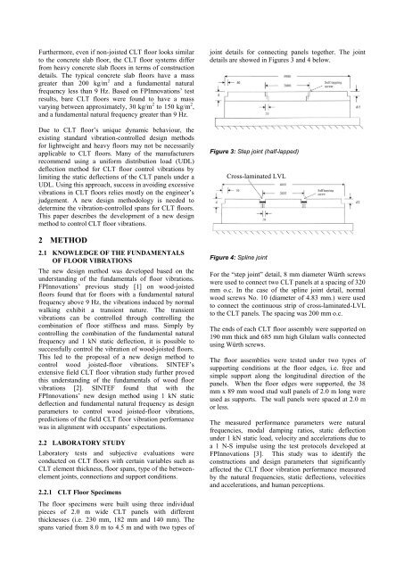
joint details for connecting panels together. The joint<br />
details are showed in Figures 3 and 4 below.<br />
Figure 3: Step joint (half-lapped)<br />
Cross-laminated LVL<br />
Figure 4: Spline joint<br />
For the “step joint” detail, 8 mm diameter Würth screws<br />
were used to connect two CLT panels at a spacing of 320<br />
mm o.c. In the case of the spline joint detail, normal<br />
wood screws No. 10 (diameter of 4.83 mm.) were used<br />
to connect the continuous strip of cross-laminated-LVL<br />
to the CLT panels. The spacing was 200 mm o.c.<br />
The ends of each CLT floor assembly were supported on<br />
190 mm thick and 685 mm high Glulam walls connected<br />
using Würth screws.<br />
The floor assemblies were tested under two types of<br />
supporting conditions at the floor edges, i.e. free and<br />
simple support along the longitudinal direction of the<br />
panels. When the floor edges were supported, the 38<br />
mm x 89 mm wood stud wall panels of 2.0 m long were<br />
used as supports. The wall panels were spaced at 2.0 m<br />
or less.<br />
The measured performance parameters were natural<br />
frequencies, modal damping ratios, static deflection<br />
under 1 kN static load, velocity and accelerations due to<br />
a 1 N-S impulse using the test protocols developed at<br />
FPInnovations [3]. This study was to identify the<br />
constructions and design parameters that significantly<br />
affected the CLT floor vibration performance measured<br />
by the natural frequencies, static deflections, velocities<br />
and accelerations, and human perceptions.


