

00078 Lin Hu - Timber Design Society
00078 Lin Hu - Timber Design Society
00078 Lin Hu - Timber Design Society

Create successful ePaper yourself
Turn your PDF publications into a flip-book with our unique Google optimized e-Paper software.
measurements were taken at each loading location to<br />
ensure that stable results were obtained. The average of<br />
three sets of the deflection profiles were used to plot the<br />
deflection profile of the test floor under the person’s<br />
weight. The deflection measurements were normalized<br />
to 1 kN load.<br />
to determine the natural frequencies, modal damping<br />
ratios and mode shapes.<br />
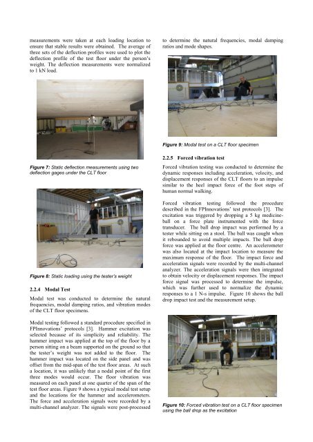
Figure 9: Modal test on a CLT floor specimen<br />
Figure 7: Static deflection measurements using two<br />
deflection gages under the CLT floor<br />
Figure 8: Static loading using the tester’s weight<br />
2.2.4 Modal Test<br />
Modal test was conducted to determine the natural<br />
frequencies, modal damping ratios, and vibration modes<br />
of the CLT floor specimens.<br />
Modal testing followed a standard procedure specified in<br />
FPInnovations’ protocols [3]. Hammer excitation was<br />
selected because of its simplicity and reliability. The<br />
hammer impact was applied at the top of the floor by a<br />
person sitting on a beam supported on the ground so that<br />
the tester’s weight was not added to the floor. The<br />
hammer impact was located on the side panel and was<br />
offset from the mid-span of the test floor areas. At such<br />
a location, it was unlikely that a nodal point of the first<br />
three modes would occur. The floor vibration was<br />
measured on each panel at one quarter of the span of the<br />
test floor areas. Figure 9 shows a typical modal test setup<br />
and the locations for the hammer and accelerometers.<br />
The force and acceleration signals were recorded by a<br />
multi-channel analyzer. The signals were post-processed<br />
2.2.5 Forced vibration test<br />
Forced vibration testing was conducted to determine the<br />
dynamic responses including acceleration, velocity, and<br />
displacement responses of the CLT floors to an impulse<br />
similar to the heel impact force of the foot steps of<br />
human normal walking.<br />
Forced vibration testing followed the procedure<br />
described in the FPInnovations’ test protocols [3]. The<br />
excitation was triggered by dropping a 5 kg medicineball<br />
on a force plate instrumented with the force<br />
transducer. The ball drop impact was performed by a<br />
tester while sitting on a stool. The ball was caught when<br />
it rebounded to avoid multiple impacts. The ball drop<br />
force was applied at the floor centre. An accelerometer<br />
was also located at the impact location to measure the<br />
maximum response of the floor. The impact force and<br />
acceleration signals were recorded by the multi-channel<br />
analyzer. The acceleration signals were then integrated<br />
to obtain velocity or displacement responses. The impact<br />
force signal was processed to determine the impulse,<br />
which was further used to normalize the dynamic<br />
responses to a 1 N-s impulse. Figure 10 shows the ball<br />
drop impact test and the measurement setup.<br />
Figure 10: Forced vibration test on a CLT floor specimen<br />
using the ball drop as the excitation


