

00078 Lin Hu - Timber Design Society
00078 Lin Hu - Timber Design Society
00078 Lin Hu - Timber Design Society

You also want an ePaper? Increase the reach of your titles
YUMPU automatically turns print PDFs into web optimized ePapers that Google loves.
CONTROLLING CROSS-LAMINATED TIMBER (CLT) FLOOR<br />
VIBRATIONS: FUNDAMENTALS AND METHOD<br />
<strong>Lin</strong> <strong>Hu</strong> 1 and Sylvain Gagnon 2<br />
ABSTRACT: Cross-Laminated <strong>Timber</strong> (CLT) is proving to be a promising solution allowing wood to compete in<br />
building sectors where traditionally steel and concrete have predominated. The dynamic behaviour of CLT floor<br />
systems differ from that of the traditional lightweight wood-joisted floors and heavy concrete slab floors. The existing<br />
standard vibration-controlled design methods for lightweight and heavy floors may not be applicable to CLT floors. A<br />
new design method was developed based on the understanding of the fundamentals of floor vibrations and laboratory<br />
study of CLT floors with various construction details. The design method predicted vibration performance of CLT<br />
floors well and matched with the subjective ratings. The new design method is simple that the vibration-controlled<br />
spans can be directly calculated from CLT stiffness and mass. The vibration-controlled spans of CLT floors predicted<br />
by this new design method were almost the same as the spans determined by “CLTdesigner” software that was<br />
developed in Austria. It is concluded that the proposed design methodology to determine vibration-controlled<br />
maximum spans of CLT floors is promising.<br />
KEYWORDS: CLT floor, Vibration, Normal Walking, <strong>Design</strong> Method<br />
1 INTRODUCTION 123<br />
Cross-Laminated <strong>Timber</strong> (CLT) is proving to be a<br />
promising solution allowing wood to compete in<br />
building sectors where traditionally steel and concrete<br />
have predominated. Figure 1 shows a typical crosssection<br />
of a CLT floor.<br />
Previous studies conducted at FPInnovations have found<br />
that bare CLT floor systems differ from traditional<br />
lightweight wood-joisted floors that have a typical mass<br />
around 20 kg/m 2 and a fundamental natural frequency<br />
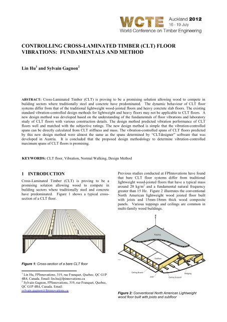
greater than 15 Hz. Figure 2 illustrates the conventional<br />
North American lightweight wood joisted floor built<br />
with joists and 15mm-18mm thick wood composite<br />
panels. Various toppings and ceilings are common in<br />
multi-family wood buildings.<br />
Figure 1: Cross-section of a bare CLT floor<br />
1 <strong>Lin</strong> <strong>Hu</strong>, FPInnovations, 319, rue Franquet, Quebec, QC G1P<br />
4R4, Canada. Email: lin.hu@fpinnovations.ca<br />
2 Sylvain Gagnon, FPInnovations, 319, rue Franquet, Quebec,<br />
QC G1P 4R4, Canada. Email:<br />
sylvain.gagnon@fpinnovations.ca<br />
Figure 2: Conventional North American Lightweight<br />
wood floor built with joists and subfloor
Furthermore, even if non-joisted CLT floor looks similar<br />
to the concrete slab floor, the CLT floor systems differ<br />
from heavy concrete slab floors in terms of construction<br />
details. The typical concrete slab floors have a mass<br />
greater than 200 kg/m 2 and a fundamental natural<br />
frequency less than 9 Hz. Based on FPInnovations’ test<br />
results, bare CLT floors were found to have a mass<br />
varying between approximately, 30 kg/m 2 to 150 kg/m 2 ,<br />
and a fundamental natural frequency greater than 9 Hz.<br />
Due to CLT floor’s unique dynamic behaviour, the<br />
existing standard vibration-controlled design methods<br />
for lightweight and heavy floors may not be necessarily<br />
applicable to CLT floors. Many of the manufacturers<br />
recommend using a uniform distribution load (UDL)<br />
deflection method for CLT floor control vibrations by<br />
limiting the static deflections of the CLT panels under a<br />
UDL. Using this approach, success in avoiding excessive<br />
vibrations in CLT floors relies mostly on the engineer’s<br />
judgement. A new design methodology is needed to<br />
determine the vibration-controlled spans for CLT floors.<br />
This paper describes the development of a new design<br />
method to control CLT floor vibrations.<br />
2 METHOD<br />
2.1 KNOWLEDGE OF THE FUNDAMENTALS<br />
OF FLOOR VIBRATIONS<br />
The new design method was developed based on the<br />
understanding of the fundamentals of floor vibrations.<br />
FPInnovations’ previous study [1] on wood-joisted<br />
floors found that for floors with a fundamental natural<br />
frequency above 9 Hz, the vibrations induced by normal<br />
walking exhibit a transient nature. The transient<br />
vibrations can be controlled through controlling the<br />
combination of floor stiffness and mass. Simply by<br />
controlling the combination of the fundamental natural<br />
frequency and 1 kN static deflection, it is possible to<br />
successfully control the vibration of wood-joisted floors.<br />
This led to the proposal of a new design method to<br />
control wood joisted-floor vibrations. SINTEF’s<br />
extensive field CLT floor vibration study further proved<br />
this understanding of the fundamentals of wood floor<br />
vibrations [2]. SINTEF found that with the<br />
FPInnovations’ new design method using 1 kN static<br />
deflection and fundamental natural frequency as design<br />
parameters to control wood joisted-floor vibrations,<br />
predictions of the field CLT floor vibration performance<br />
was in alignment with occupants’ expectations.<br />
2.2 LABORATORY STUDY<br />
Laboratory tests and subjective evaluations were<br />
conducted on CLT floors with certain variables such as<br />
CLT element thickness, floor spans, type of the betweenelement<br />
joints, connections and support conditions.<br />
2.2.1 CLT Floor Specimens<br />
The floor specimens were built using three individual<br />
pieces of 2.0 m wide CLT panels with different<br />
thicknesses (i.e. 230 mm, 182 mm and 140 mm). The<br />
spans varied from 8.0 m to 4.5 m and with two types of<br />
joint details for connecting panels together. The joint<br />
details are showed in Figures 3 and 4 below.<br />
Figure 3: Step joint (half-lapped)<br />
Cross-laminated LVL<br />
Figure 4: Spline joint<br />
For the “step joint” detail, 8 mm diameter Würth screws<br />
were used to connect two CLT panels at a spacing of 320<br />
mm o.c. In the case of the spline joint detail, normal<br />
wood screws No. 10 (diameter of 4.83 mm.) were used<br />
to connect the continuous strip of cross-laminated-LVL<br />
to the CLT panels. The spacing was 200 mm o.c.<br />
The ends of each CLT floor assembly were supported on<br />
190 mm thick and 685 mm high Glulam walls connected<br />
using Würth screws.<br />
The floor assemblies were tested under two types of<br />
supporting conditions at the floor edges, i.e. free and<br />
simple support along the longitudinal direction of the<br />
panels. When the floor edges were supported, the 38<br />
mm x 89 mm wood stud wall panels of 2.0 m long were<br />
used as supports. The wall panels were spaced at 2.0 m<br />
or less.<br />
The measured performance parameters were natural<br />
frequencies, modal damping ratios, static deflection<br />
under 1 kN static load, velocity and accelerations due to<br />
a 1 N-S impulse using the test protocols developed at<br />
FPInnovations [3]. This study was to identify the<br />
constructions and design parameters that significantly<br />
affected the CLT floor vibration performance measured<br />
by the natural frequencies, static deflections, velocities<br />
and accelerations, and human perceptions.
2.2.2 Subjective Evaluation<br />
The key objective of the subjective evaluation of<br />
vibration performance is to define the maximum<br />
annoying vibration level that can be acceptable to the<br />
majority of occupants of residential floors.<br />
To more closely mimic normal living conditions during<br />
subjective performance evaluations, the CLT floor<br />
assemblies were carpeted and furnished with a cabinet<br />
and two vases filled with water and flowers, as shown in<br />
Figures 5 and 6. The reason for decorating the china<br />
cabinet using flowers and water is because these objects<br />
are good indicators of floor excessive vibrations. If the<br />
floor is vibrating at high level when a person is walking<br />
by the cabinet, he/she will notice the flower and the<br />
water moving. In Figure 6, you also can see some kind<br />
of china cabinet with glassware. It has been observed<br />
that the glassware in the china cabinet is another good<br />
indicator of excessive vibrations. Typically, with poor<br />
floors, one can easily notice the rattling of glassware in<br />
the room. In these Figures, you could also see a chair<br />
located in the centre of the floor. During the subjective<br />
evaluation, if the person is sitting on the chair and feels<br />
the floor vibrating when someone is walking by the<br />
chair, then the floor vibration is most likely not<br />
acceptable.<br />
Figure 6: Subjective evaluation while the evaluator is<br />
sitting, feeling, and observing the floor movement<br />
The evaluator was then asked to sit on the chair, while<br />
another person would walk on the floor according to a<br />
pre-designated pattern (Figure 6). The walking pattern is<br />
such that the person walks at least two times along the<br />
two diagonal directions from one corner of the floor to<br />
the other, then walks at least two times along the middle<br />
lines in the parallel and perpendicular directions of the<br />
subfloor panels. Again the evaluator was observing the<br />
three clues, i.e. seeing, hearing and feeling regarding<br />
floor vibration performance. Immediately after the<br />
evaluation, the evaluator is asked to fill out a<br />
questionnaire which provided an overall performance<br />
rating for the floor as well as a score for the three key<br />
performance-related clues.<br />
2.2.3 Static Concentrated Load Test<br />
This test was conducted to determine the maximum<br />
static deflection of the floor under a 1 kN concentrated<br />
static load. This is a measure of the entire stiffness of the<br />
floor.<br />
Figure 5: Subjective evaluation while the evaluator is<br />
walking, feeling, and observing the floor movement<br />
At least twenty persons were asked to evaluate the<br />
performance of a floor subjectively. Only one evaluator<br />
was allowed on the floor at a time. He or she first walked<br />
freely on the floor while observing clues related to floor<br />
performance (Figure 5). The clues included movement of<br />
the flowers and the water, rattling of the china cabinet,<br />
and feeling the movement of the floor.<br />
The basic elements needed to measure static deflection<br />
under a concentrated load are: 1) a stable reference from<br />
which to measure floor movement, 2) an accurate and<br />
sensitive deflection measuring device, and 3) a mobile<br />
loading system. In this study, the concrete ground floor<br />
was used as the reference. Two electronic gauges having<br />
a resolution of 0.001 mm were used as the deflection<br />
measuring devices as shown in Figure 7. The deflection<br />
gauges were mounted to the free ends of two rods in<br />
contact with the concrete ground floor surface. The end<br />
of one deflection gage was fixed to the bottom of the<br />
middle point of the centre CLT panel to measure the<br />
static deflection of the floor centre. The end of the<br />
second deflection gauge was fixed to the bottom of the<br />
middle point of the joint of two CLT panels to measure<br />
the static deflection of the joint. The concentrated static<br />
load was applied by a person standing over each CLT<br />
panel’s centre, floor edges and the joints in turn while<br />
recording the measurement at the gauge location. Figure<br />
8 shows the static loading process using the tester’s<br />
weight. The deflection profile of the floor was generated<br />
from a complete set of measurements. Three
measurements were taken at each loading location to<br />
ensure that stable results were obtained. The average of<br />
three sets of the deflection profiles were used to plot the<br />
deflection profile of the test floor under the person’s<br />
weight. The deflection measurements were normalized<br />
to 1 kN load.<br />
to determine the natural frequencies, modal damping<br />
ratios and mode shapes.<br />
Figure 9: Modal test on a CLT floor specimen<br />
Figure 7: Static deflection measurements using two<br />
deflection gages under the CLT floor<br />
Figure 8: Static loading using the tester’s weight<br />
2.2.4 Modal Test<br />
Modal test was conducted to determine the natural<br />
frequencies, modal damping ratios, and vibration modes<br />
of the CLT floor specimens.<br />
Modal testing followed a standard procedure specified in<br />
FPInnovations’ protocols [3]. Hammer excitation was<br />
selected because of its simplicity and reliability. The<br />
hammer impact was applied at the top of the floor by a<br />
person sitting on a beam supported on the ground so that<br />
the tester’s weight was not added to the floor. The<br />
hammer impact was located on the side panel and was<br />
offset from the mid-span of the test floor areas. At such<br />
a location, it was unlikely that a nodal point of the first<br />
three modes would occur. The floor vibration was<br />
measured on each panel at one quarter of the span of the<br />
test floor areas. Figure 9 shows a typical modal test setup<br />
and the locations for the hammer and accelerometers.<br />
The force and acceleration signals were recorded by a<br />
multi-channel analyzer. The signals were post-processed<br />
2.2.5 Forced vibration test<br />
Forced vibration testing was conducted to determine the<br />
dynamic responses including acceleration, velocity, and<br />
displacement responses of the CLT floors to an impulse<br />
similar to the heel impact force of the foot steps of<br />
human normal walking.<br />
Forced vibration testing followed the procedure<br />
described in the FPInnovations’ test protocols [3]. The<br />
excitation was triggered by dropping a 5 kg medicineball<br />
on a force plate instrumented with the force<br />
transducer. The ball drop impact was performed by a<br />
tester while sitting on a stool. The ball was caught when<br />
it rebounded to avoid multiple impacts. The ball drop<br />
force was applied at the floor centre. An accelerometer<br />
was also located at the impact location to measure the<br />
maximum response of the floor. The impact force and<br />
acceleration signals were recorded by the multi-channel<br />
analyzer. The acceleration signals were then integrated<br />
to obtain velocity or displacement responses. The impact<br />
force signal was processed to determine the impulse,<br />
which was further used to normalize the dynamic<br />
responses to a 1 N-s impulse. Figure 10 shows the ball<br />
drop impact test and the measurement setup.<br />
Figure 10: Forced vibration test on a CLT floor specimen<br />
using the ball drop as the excitation
3 RESULTS<br />
3.1 KEY CONSTRUCTION AND DESIGN<br />
PARAMETER<br />
Based on data analysis, it was found that the<br />
combination of fundamental natural frequency with 1 kN<br />
static deflection, or with acceleration, or with velocity<br />
was well correlated to human perception. It is<br />
understood that the fundamental natural frequency is<br />
mainly controlled by the longitudinal stiffness and the<br />
mass, while the 1 kN static deflection is determined by<br />
the entire stiffness of the CLT floor in both the<br />
longitudinal and lateral directions. The acceleration or<br />
velocity is determined by the excitation, the entire<br />
stiffness and by damping ratio. It has been wellrecognized<br />
that determining the damping ratio accurately<br />
and to a certain reliability level of is not easy.<br />
Reproducibility is another issue. Besides, damping is<br />
largely controlled by the floor constructions details such<br />
as the joints, connections, and support conditions, and<br />
the non-structural components such as potions, flooring,<br />
toppings, insulation materials, furniture, etc. Moreover,<br />
the modal test results showed that, for the bare CLT<br />
floors tested, the measured damping ratio did not vary<br />
from one assembly to another as it was quit constant<br />
with a value of around 1%.<br />
Based on the laboratory study results, it has been found<br />
that in meeting the safety requirements for the supports<br />
and joints, the vibration performance of CLT floors were<br />
largely controlled by the CLT stiffness along the<br />
longitudinal direction and by the mass. The type of joints<br />
between the CLT panels did not significantly affect the<br />
measured fundamental natural frequencies, the 1 kN<br />
static deflections, and the subjective ratings. Therefore,<br />
it was decided to use the stiffness in the longitudinal<br />
direction and the mass as the key parameters in the<br />
design method to control CLT floor vibrations through a<br />
combination of fundamental natural frequency and 1 kN<br />
static deflection.<br />
3.2 PROPOSED DESIGN METHOD<br />
The proposed design method to control CLT floor<br />
vibrations consists of a design criterion and the relevant<br />
equations to calculate the design parameters.<br />
3.2.1 Scope<br />
At this point, the scope of the proposed design method to<br />
control vibrations of CLT floors covers the following<br />
1. bare floors with finishing, partitions and<br />
furniture, but without heavy topping,<br />
2. vibrations-induced by normal walking,<br />
3. well-supported floors,<br />
4. well-jointed CLT panels, and<br />
5. inclusion of the self weight of CLT panels only<br />
(i.e. without live load).<br />
cover various types of toppings and ceilings, and other<br />
floor design options.<br />
3.2.2 Advantages<br />
The proposed design method is focused on target<br />
features, which include, among others<br />
1. simple for hand calculation,<br />
2. user-friendly,<br />
3. mechanics-based using the design values CLT<br />
panels available in producer’s specification,<br />
4. reliable to prevent CLT floors from excessive<br />
vibrations induced by normal walking.<br />
3.2.3 <strong>Design</strong> Criterion<br />
Based on the understanding of the fundamentals of floor<br />
vibrations and the special features of CLT floor<br />
vibrations, and following the laboratory test results, a<br />
proposed simple design criterion using fundamental<br />
natural frequency and 1 kN static deflection of a simple<br />
1-m wide CLT panel as design parameters has been<br />
developed.<br />
The design criterion is expressed in Equation (1).<br />
f<br />
d<br />
<br />
0.7<br />
13.0<br />
Or<br />
1.43<br />
f<br />
d <br />
39<br />
where f = fundamental natural frequency calculated<br />
using Equation (2) in Hz, and d = 1 kN static deflection<br />
calculated using Equation (3) in mm.<br />
3.2.4 Equations to Calculate the <strong>Design</strong> Parameters<br />
f<br />
3.142<br />
2<br />
2l<br />
EI<br />
1m<br />
eff<br />
A<br />
(1)<br />
(2)<br />
where, f = fundamental natural frequency of 1m CLT<br />
panel simply supported in Hz, l= CLT floor span in m,<br />
EI 1<br />
m<br />
eff<br />
= effective apparent stiffness in the span direction<br />
which is published by the producers for 1m wide panel<br />
in N-m 2 , = density of CLT in kg/m 3 , and A = crosssection<br />
area of 1-m wide CLT panel, i.e. thickness*1m<br />
width in m 2 . The static deflection under 1 kN load can be<br />
calculated using Equation (3) below.<br />
3<br />
1000Pl<br />
(3)<br />
d<br />
1m<br />
48EI eff<br />
where, d = static deflection at mid-span of the 1m wide<br />
simply supported CLT panel under 1 kN load in mm,<br />
and P = 1000 N.<br />
However, because of the mechanics-based feature, it is<br />
possible to expand its scope to include other construction<br />
details. A study has been planned to extend the scope to
1kN static deflection calculated<br />
using Eq.2 (mm)<br />
3.2.5 Verification<br />
Figure 11 shows a comparison of predictions using the<br />
proposed new design methodology to predict the CLT<br />
floor vibrations and corresponding subjective ratings by<br />
evaluators.<br />
2.00<br />
1.50<br />
1.00<br />
0.50<br />
Predicted CLT floor vibration performance vs.<br />
subjective ratings<br />
criterion ( f/d^0.7>13.0)<br />
Unacceptable<br />
Marginal<br />
Acceptable<br />
0.00<br />
0 5 10 15 20<br />
Fundamental Natrual frequency calculated using Eq. 1 (Hz)<br />
Figure 11: Predicted CLT floor vibration performance by<br />
the proposed design method vs. subjective rating by<br />
participants<br />
3.2.6 Simple Form of the <strong>Design</strong> Method<br />
Inserting Equations (2) and (3) into the design criterion,<br />
i.e. Equation (1), it is possible to obtain a simple form of<br />
the design method which can be expressed by Equation<br />
(4) as given below.<br />
l<br />
1<br />
9.15<br />
( EI<br />
1m<br />
0.293<br />
eff<br />
0.123<br />
( A)<br />
)<br />
(4)<br />
Using Equation (4), it is possible to determine the<br />
vibration controlled spans for CLT floors directly from<br />
the effective apparent stiffness in the span direction,<br />
density and cross-section area of 1m wide CLT panels.<br />
3.2.7 Impact Study<br />
The vibration controlled CLT floor spans determined<br />
using the proposed design method were compared with<br />
the spans determined by CLTdesigner developed at<br />
university of Graz in Austria [4]. Table 1 provides the<br />
comparison.<br />
Table 1: Vibration controlled CLT floor spans determined<br />
using the new design method vs. the spans determined<br />
by “CLTdesigner”<br />
CLT<br />
Thickness<br />
(mm)<br />
Span<br />
Determined<br />
by the<br />
Proposed<br />
Method<br />
(m)<br />
Span<br />
Determined by<br />
“CLTdesigner”<br />
for 1%<br />
Damping<br />
100 3.58 3.53<br />
120 3.76 3.75<br />
140 4.50 4.43<br />
160 4.80 4.76<br />
180 5.16 5.14<br />
200 5.68 5.67<br />
220 5.84 5.89<br />
240 6.09 6.17<br />
As given in Table 1, the vibration controlled spans of<br />
bare CLT floors predicted by this new design method<br />
were very close to those spans determined by<br />
CLTdesigner.<br />
4 CONCLUSIONS<br />
It is concluded that the proposed design methodology to<br />
determine vibration-controlled maximum spans of bare<br />
CLT floors is promising. This methodology uses only<br />
the design values of CLT mechanical properties. The<br />
method is simple, user-friendly, and reliable.<br />
Wide acceptance of the proposed design method relies<br />
on the use and evaluation of the method by productmanufacturers<br />
and designers. FPInnovations is open to<br />
feedback and ready to adopt and further refine the design<br />
method according to the needs of the producers and<br />
designers. The current form of the design method is for<br />
CLT floors without heavy topping. A study of the effect<br />
of heavy topping on the vibration performance of CLT<br />
floors is under way.<br />
ACKNOWLEDGEMENT<br />
FPInnovations would like to thank its industry members<br />
and Natural Resources Canada (Canadian Forest<br />
Service) for their financial support of this work.<br />
The authors wish to thank KLH for providing CLT<br />
panels for this study and the guidance on CLT floor<br />
construction. Thanks are also extended to Mr. Thomas<br />
Orskaug of Moelven Massivtre AS (Now of KLH Solid<br />
Wood Scandinavia AB) and Dr. Anders Homb of<br />
SINTEF Byggforsk for sharing their experience of<br />
massive wood slab non-joisted floor systems with us and<br />
for providing the opportunity to visit CLT buildings in<br />
Norway. Thanks are also extended to Dr. Gerhard<br />
Schickhofer of Graz Institut für Holzbau und<br />
Holztechnologie, Austria for conducting the comparison<br />
given in Table 1.
REFERENCES<br />
[1] <strong>Hu</strong> J.: <strong>Design</strong> guide for wood-framed floor systems.<br />
Final report No.32 for Canadian Forestry Service.<br />
FPInnovations, Quebec, 2007.<br />
[2] Homb A.: Vibrasjonsegenskaper til dekker av<br />
massivtre (in Norwagien). Report of Prosjektrapport<br />
24, Sintef Byggforsk, Norway, 2008.<br />
[3] <strong>Hu</strong> J.: Protocols for field testing of wood-based<br />
floor systems. Appendix V in Report of<br />
Serviceability design criteria for commercial and<br />
multi-family floors. Report No. 3 for Canadian<br />
Forest Service, FPInnovations, Quebec, 1998.<br />
[4] Schickhofer G.: Comments on FPInnovations new<br />
design method for CLT floor vibration control.<br />
Private e-mail provided the link to access to<br />
CLTdesigner,2010:<br />
http://www.cltdesigner.at/webstart/testversion/cltdes<br />
ignertestversion.jnlp


