You also want an ePaper? Increase the reach of your titles
YUMPU automatically turns print PDFs into web optimized ePapers that Google loves.
T 2.4/8.1/B/1<br />
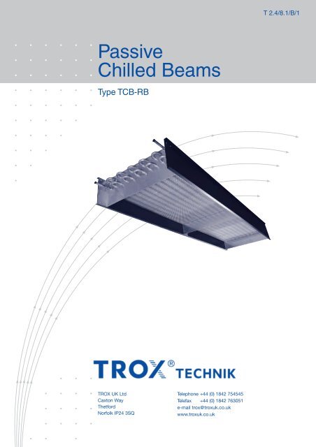
Passive<br />
Chilled Beams<br />
Type <strong>TCB</strong>-<strong>RB</strong><br />
<strong>TROX</strong> UK Ltd<br />
Caxton Way<br />
Thetford<br />
Norfolk IP24 3SQ<br />
Telephone +44 (0) 1842 754545<br />
Telefax +44 (0) 1842 763051<br />
e-mail trox@troxuk.co.uk<br />
www.troxuk.co.uk
Contents · Description<br />
Contents · Description __________________________ 2<br />
Construction · Dimensions _______________________ 3<br />
Installation · Assembly __________________________ 4<br />
Nomenclature · Example ________________________ 5<br />
Quick Selection 1 row coil _______________________ 6<br />
Quick Selection 2 row coil _______________________ 7<br />
Technical Data 1 row coil ________________________ 8<br />
Technical Data 2 row coil ________________________ 9<br />
Technical Data Air Boot _________________________ 10<br />
Order Details __________________________________ 11<br />
Type <strong>TCB</strong>-<strong>RB</strong><br />
Type <strong>TCB</strong>-<strong>RB</strong>-S<br />
Description<br />
Passive chilled beams are a very simple yet effective cooling<br />
device, used for dissipation of high internal heat loads. They<br />
offer low investment costs ideal for refurbishment or new build<br />
projects.<br />
The absence of any moving parts, and the use of quality<br />
materials in the construction of this product offers a silent,<br />
low maintenance cooling solution.<br />
<strong>TROX</strong> type <strong>TCB</strong>-<strong>RB</strong> beams are suitable for mounting within a<br />
ceiling void above a perforated ceiling tile or can be freely<br />
suspended.<br />
Using water as a cooling medium, <strong>TROX</strong> passive chilled beams<br />
provide energy benefits over traditional cooling systems.<br />
Caution!<br />
The chilled water flow temperature should be selected<br />
so as to avoid operation below dew point.<br />
2
Construction · Dimensions<br />
Construction<br />
<strong>TROX</strong> <strong>TCB</strong>-<strong>RB</strong> passive chilled beam comprises a cooling<br />
coil & casing with return edges, which provide mounting points<br />
suit able for Ø 8 mm drop rods or suitable wire supports.<br />
For lower free area ceilings (< 40%) <strong>TROX</strong> <strong>TCB</strong>-<strong>RB</strong>-S should be<br />
used. The flexible PVC skirt material is mechanically fixed to<br />
bottom of casing providing directional control of discharge air<br />
through ceiling into occupied zone.<br />
Materials<br />
Casing is galvanised steel sheet, cooling coil manufactured from<br />
high grade copper pipework with self finish aluminium fins.<br />
Flexible skirt is made from high quality plasticized PVC polymer<br />
direct coated onto both sides of polyester substrate.<br />
Standard casing surface finish of <strong>TCB</strong>-<strong>RB</strong> units is black (RAL<br />
9005) powder coat, coil natural finish. Other RAL colours are<br />
available on request.<br />
Dimensions in mm<br />
L 1 (mm) L 2 (mm) B (mm) W (mm) H (mm)<br />
1200<br />
4500<br />
1200 258 300 200<br />
1500 309 351 250<br />
1800 360 402 300<br />
2100 410 452<br />
2400 461 503<br />
2700 512 554<br />
3000 563 605<br />
614 656<br />
Casing<br />
PVC Skirt<br />
Coil flow and return water connections<br />
(Ø 15 mm plain copper tube)<br />
Support flange<br />
Airboot Plenum<br />
Type <strong>TCB</strong>-<strong>RB</strong> beams can be supplied in various lengths in<br />
100 mm increments.<br />
<br />
<br />
<br />
<br />
<br />
<br />
<br />
<br />
<br />
<br />
<br />
<br />
<br />
<br />
<br />
<br />
<br />
<br />
L 1<br />
L 2<br />
= Total beam length<br />
= Airboot plenum length<br />
B = Coil width<br />
W = Overall width<br />
H 1 = Overall height<br />
<br />
3
Installation · Assembly<br />
For the convection process to occur, it is essential that the air<br />
to be cooled can flow unhindered into the coil. The optimum<br />
condition for this is when distance Z – lower edge of ceiling slab<br />
to upper edge of beam is as large as possible (ideally Z W/2).<br />
It is also important to allow return air to enter the ceiling void.<br />
The return air path free area should be equivalent to the coil<br />
area and be split equally either side of the chilled beam. For<br />
example, if a perforated ceiling with a 50% free area is on the<br />
return air path, then the perforated area should be equal to twice<br />
the width x length of the coil.<br />
<strong>TROX</strong> <strong>TCB</strong>-<strong>RB</strong> chilled beams are provided with Ø10 mm holes,<br />
pre-punched within the top flange.<br />
The chilled beams can be suspended from the slab with<br />
threaded rod or suitable suspension wires.<br />
Beam Weight<br />
Beam Type Weight (kg/m)<br />
<strong>TCB</strong>-<strong>RB</strong> / <strong>RB</strong>-S 15<br />
Airboot 5<br />
<strong>TCB</strong>-<strong>RB</strong> mounting detail<br />
L <br />
1 = 1200 mm up to 2999 mm<br />
L 1 = 3000 mm up to 4500 mm<br />
<br />
Coil Connection Detail<br />
<br />
Horizontal connection<br />
<br />
<br />
Vertical connection<br />
<br />
<br />
<br />
<br />
<br />
<br />
<br />
<br />
<br />
<br />
<br />
<br />
<br />
<br />
<br />
<br />
<br />
<br />
<br />
<br />
<br />
<br />
<br />
<br />
4
Nomenclature · Example<br />
Nomenclature<br />
V WK in l/hr: Water volume flow rate, cooling<br />
Q WK in W: Water cooling capacity<br />
q WK in W/m: Specific cooling capacity per m<br />
W/m²: or per m²<br />
t WV in °C: Chilled water flow temperature<br />
t WR in °C: Chilled water return temperature<br />
t WM in °C: Chilled water mean temperature<br />
t R in °C: Maximum room air temperature<br />
t W in K: Temperature difference between water<br />
flow and return temperature<br />
t RW in K: Temperature difference between max.<br />
room air temperature and mean chilled<br />
water temperature<br />
V in m/s: Maximum time averaged air velocity<br />
measured<br />
approx. 1 m below passive chilled beam<br />
B in mm: Width of cooling coil<br />
H in mm: Passive beam stack height<br />
fo in %: Ceiling free area underneath the <strong>TCB</strong>-<strong>RB</strong><br />
Z in mm: Return air gap above beam<br />
K Z/W<br />
Correction factor for Z /W ratio<br />
K fo<br />
Correction factor for airflow % free area<br />
p W in kPa: Water pressure drop<br />
Reference Values<br />
t WV = 16 °C Chilled water flow temperature<br />
t WR = 18 °C Chilled water return temperature<br />
t R = 27 °C Room air temperature<br />
t RW = 10 K Temperature difference between room<br />
air temperature and mean chilled water<br />
temperature<br />
Z/W = 0.5 Ratio of clear height against coil width<br />
Example<br />
Room size: 3 m x 6 m<br />
Room height: 2.8 m<br />
Suspended ceiling: 45% free area<br />
Ceiling void: 400 mm<br />
t R 24 °C<br />
t WV 14 °C<br />
t WR 17 °C<br />
t RW 8.5 K<br />
q WK 60 W/m²<br />
60 x 3 x 6 = 1080 W<br />
Q WK<br />
The architect has specified a row of units maximum 6 m<br />
along the centre line of the room (2 x 3 m)<br />
<br />
<br />
Room sketch<br />
Diagrams I…III (see page 8)<br />
Coil width (B): 410 mm<br />
Unit height (H): 250 mm<br />
Unit length (L 1 ): 3000 mm Q = 550 W<br />
For installation behind a perforated ceiling 45%,<br />
correction factor K fo must be applied.<br />
K fo : 0.99 Q = 550 W x 0.99 = 544 W<br />
Diagrams IV and V<br />
At a differential between water flow and return temperature<br />
of 3 K, the water flow rate V W = 156 l/hr. Since the water flow<br />
rate is greater then the nominal water flow rate of 110 l/hr,<br />
a correction factor K W = 1.07 is applied to the calculated<br />
capacity<br />
Q = 544 W x 1.07 = 582 W<br />
Diagram VII<br />
For installation within a ceiling void, correction factor K Z/W<br />
must be applied.<br />
Z<br />
B<br />
= (400-250) = 0.36<br />
410<br />
K Z/W : 0.97 Q = 582 W x 0.97 = 565 W<br />
For the room as planned with 2 chilled beams units<br />
3000 mm long, the available overall cooling capacity is:<br />
Q WK = 2 x 565 W = 1130 W<br />
Diagram VII<br />
Waterside pressure drop.<br />
p w = 0.7 x 3 m = 2.1 kPa<br />
Diagram VIII<br />
The air velocity 1 m below the chilled beam will be between<br />
0.17 and 0.23 m/s.<br />
NOTE: If required cooling output cannot be achieved with<br />
a 1 row coil, repeat above steps with diagrams on page 9.<br />
5
Quick Selection<br />
1 row coil<br />
Note: Diagram VIII on page 8 shows the maximum time<br />
averaged air velocity measured approximately 1m below the<br />
passive beam as a function of the output per linear meter.<br />
Cooling capacities below should be selected in line with the<br />
required comfort conditions and are subject to corrections by<br />
using the appropriate diagrams on page 8.<br />
Cooling capacity (W/m) at t RW = 10 K Z/W ~ 0.5<br />
1 Row<br />
W =<br />
258 mm,<br />
Z =<br />
130 mm<br />
W =<br />
309 mm,<br />
Z =<br />
150 mm<br />
W =<br />
360 mm,<br />
Z =<br />
180 mm<br />
W =<br />
410 mm,<br />
Z =<br />
200 mm<br />
W =<br />
461 mm,<br />
Z =<br />
230 mm<br />
W =<br />
512 mm,<br />
Z =<br />
250 mm<br />
W =<br />
563 mm,<br />
Z =<br />
280 mm<br />
W =<br />
614 mm,<br />
Z =<br />
300 mm<br />
H (mm) fo 1) 50 % 50 % 50 % 50 % 50 % 50 % 50 % 50 %<br />
150 142 161 185 207 227 247 260 276<br />
200 149 170 194 218 241 260 274 290<br />
250 157 179 204 230 258 273 288 305<br />
300 164 188 213 241 270 286 302 319<br />
Cooling capacity (W/m) at t RW = 8 K Z/W ~ 0.5<br />
1 Row<br />
W =<br />
258 mm,<br />
Z =<br />
130 mm<br />
W =<br />
309 mm,<br />
Z =<br />
150 mm<br />
W =<br />
360 mm,<br />
Z =<br />
180 mm<br />
W =<br />
410 mm,<br />
Z =<br />
200 mm<br />
W =<br />
461 mm,<br />
Z =<br />
230 mm<br />
W =<br />
512 mm,<br />
Z =<br />
250 mm<br />
W =<br />
563 mm,<br />
Z =<br />
280 mm<br />
W =<br />
614 mm,<br />
Z =<br />
300 mm<br />
H (mm) fo 1) 50 % 50 % 50 % 50 % 50 % 50 % 50 % 50 %<br />
150 114 131 148 168 188 199 210 221<br />
200 120 138 157 176 198 209 221 233<br />
250 127 146 165 186 208 220 233 245<br />
300 133 153 173 194 218 230 244 257<br />
Cooling capacity (W/m) at t RW = 7 K Z/W ~ 0.5<br />
1 Row<br />
W =<br />
258 mm,<br />
Z =<br />
130 mm<br />
W =<br />
309 mm,<br />
Z =<br />
150 mm<br />
W =<br />
360 mm,<br />
Z =<br />
180 mm<br />
W =<br />
410 mm,<br />
Z =<br />
200 mm<br />
W =<br />
461 mm,<br />
Z =<br />
230 mm<br />
W =<br />
512 mm,<br />
Z =<br />
250 mm<br />
W =<br />
563 mm,<br />
Z =<br />
280 mm<br />
W =<br />
614 mm,<br />
Z =<br />
300 mm<br />
H (mm) fo 1) 50 % 50 % 50 % 50 % 50 % 50 % 50 % 50 %<br />
150 100 114 130 147 165 175 184 195<br />
200 105 120 137 155 174 184 194 206<br />
250 111 127 144 163 183 194 204 216<br />
300 116 133 151 171 192 203 214 227<br />
1)<br />
fo: ceiling free area underneath the <strong>TCB</strong>-<strong>RB</strong><br />
6
Quick Selection<br />
2 row coil<br />
Cooling capacity (W/m) at t RW = 10 K Z/W ~ 0.5<br />
2 Row<br />
W =<br />
360 mm,<br />
Z =<br />
180 mm<br />
W =<br />
410 mm,<br />
Z =<br />
200 mm<br />
W =<br />
461 mm,<br />
Z =<br />
230 mm<br />
W =<br />
512 mm,<br />
Z =<br />
250 mm<br />
W =<br />
563 mm,<br />
Z =<br />
280 mm<br />
W =<br />
614 mm,<br />
Z =<br />
300 mm<br />
H (mm) fo 1) 50 % 50 % 50 % 50 % 50 % 50 %<br />
150 223 271 328 368 408 448<br />
200 235 286 345 387 429 472<br />
250 247 301 363 407 451 496<br />
300 259 316 380 426 472 520<br />
Cooling capacity (W/m) at t RW = 8 K Z/W ~ 0.5<br />
2 Row<br />
W =<br />
360 mm,<br />
Z =<br />
180 mm<br />
W =<br />
410 mm,<br />
Z =<br />
200 mm<br />
W =<br />
461 mm,<br />
Z =<br />
230 mm<br />
W =<br />
512 mm,<br />
Z =<br />
250 mm<br />
W =<br />
563 mm,<br />
Z =<br />
280 mm<br />
W =<br />
614 mm,<br />
Z =<br />
300 mm<br />
H (mm) fo 1) 50 % 50 % 50 % 50 % 50 % 50 %<br />
150 166 205 248 278 311 342<br />
200 175 216 261 293 327 360<br />
250 184 227 274 308 344 379<br />
300 193 238 287 323 360 397<br />
Cooling capacity (W/m) at t RW = 7 K Z/W ~ 0.5<br />
2 Row<br />
W =<br />
360 mm,<br />
Z =<br />
180 mm<br />
W =<br />
410 mm,<br />
Z =<br />
200 mm<br />
W =<br />
461 mm,<br />
Z =<br />
230 mm<br />
W =<br />
512 mm,<br />
Z =<br />
250 mm<br />
W =<br />
563 mm,<br />
Z =<br />
280 mm<br />
W =<br />
614 mm,<br />
Z =<br />
300 mm<br />
H (mm) fo 1) 50 % 50 % 50 % 50 % 50 % 50 %<br />
150 137 171 208 235 261 290<br />
200 144 180 219 247 275 305<br />
250 152 189 230 260 289 320<br />
300 159 198 241 272 303 335<br />
1)<br />
fo: ceiling free area underneath the <strong>TCB</strong>-<strong>RB</strong><br />
7
Technical Data<br />
1 row coil<br />
I<br />
II<br />
<br />
<br />
III<br />
Δ <br />
<br />
<br />
IV<br />
V<br />
Δ <br />
Δ <br />
Perforated plate<br />
correction factor K fo<br />
Free area fo<br />
in %<br />
K fo<br />
30% 0.94<br />
35% 0.96<br />
40 % 0.98<br />
45 % 0.99<br />
50 % 1<br />
<br />
<br />
VI<br />
VII<br />
VIII<br />
Δ <br />
<br />
<br />
<br />
<br />
<br />
<br />
8
Technical Data<br />
2 row coil<br />
I<br />
II<br />
III<br />
<br />
Δ <br />
<br />
<br />
IV<br />
V<br />
Δ <br />
Δ <br />
Perforated plate<br />
correction factor K fo<br />
Free area fo<br />
in %<br />
K fo<br />
30% 0.94<br />
35% 0.96<br />
40 % 0.98<br />
45 % 0.99<br />
50 % 1<br />
VI<br />
<br />
VII<br />
<br />
<br />
VIII<br />
Δ <br />
<br />
<br />
<br />
<br />
<br />
9
Technical Data<br />
Airboot<br />
Description<br />
<strong>TROX</strong> trickle vent airboot plenum (<strong>TCB</strong>-AIR) is a 2 nd fix plenum<br />
assembly that can be installed on either side of the <strong>TCB</strong>-<strong>RB</strong><br />
passive chilled beam range.<br />
The airboot plenum assembly is designed to deliver fresh air<br />
into the space with a side entry air spigot connection.<br />
The fresh air is delivered along the length of the plenum via an<br />
integral balancing plate with a very low pressure drop.<br />
Construction / Assembly<br />
<strong>TROX</strong> <strong>TCB</strong>-AIR plenum assembly is made from galvanised steel<br />
sheet.<br />
Flexible skirt is made from high quality plasticized PVC polymer<br />
direct coated onto both sides of polyester substrate.<br />
Standard casing surface finish of <strong>TCB</strong>-AIR unit is black<br />
(RAL 9005) powder coat. Other RAL colours are available on<br />
request.<br />
To achieve comfort conditions within the occupied space, it is<br />
recommended that the ventilation air is discharged at isothermal<br />
conditions when airboot plenum is used. If this can not be achieved,<br />
extra attention should be given to maintaining low discharge<br />
velocities.<br />
Airboot performance<br />
L 2 (mm) Airflow (l/s) p (Pa)<br />
1200 14 2<br />
1500 18 3<br />
1800 22 3<br />
2100 25 4<br />
2400 28 6<br />
2700 32 7<br />
3000 36 8<br />
10
Order details<br />
Specification text<br />
Type <strong>TCB</strong>-<strong>RB</strong> passive chilled beam is used to dissipate high<br />
internal heat loads using chilled water.<br />
Materials<br />
Casing is galvanised steel sheet, cooling coil manufactured from<br />
high grade copper pipework with self finish aluminium fins.<br />
It comprises a casing, manufactured from galvanised steel with<br />
integrated mounting points for threaded rod or suspension wire<br />
supports.<br />
Cooling coil has high grade copper tubes with formed aluminium<br />
fins promoting efficient transfer of heat energy from the room to<br />
the cooling medium.<br />
Flexible skirt is made from high quality plasticized PVC polymer<br />
direct coated onto both sides of polyester substrate.<br />
Standard casing surface finish of <strong>TCB</strong>-<strong>RB</strong> units is black (RAL<br />
9005) powder coat, coil natural fin. Other RAL colours are available<br />
on request.<br />
Order code<br />
<strong>TCB</strong>-<strong>RB</strong> – UK – 00 – S / 3000 x 450 x 200 / 2H – 1 – N / P4 / RAL 9005 / 20 %<br />
1 2 3 4 5 6 7 8 9 10 11 12 13<br />
1 – TYPE<br />
2 – MARKET<br />
- UK<br />
- USA<br />
3 – NOT USED<br />
4 – SKIRT<br />
- 0 [No Skirt]<br />
- S [Skirt]<br />
5 – BEAM LENGTH (L 1 )<br />
- 1200 – 4500<br />
6 – COIL WIDTH (W)<br />
- 207<br />
- 258<br />
- 309<br />
- 360<br />
- 410<br />
- 461<br />
- 512<br />
- 563<br />
- 614<br />
7 – STACK HEIGHT (H)<br />
- 200<br />
- 250<br />
- 300<br />
8 – COIL ROWS<br />
- 1V [1 Row Vertical Connections]<br />
- 1H [1 Row Horizontal Connections]<br />
- 2V [2 Row Vertical Connections]<br />
- 2H [2 Row Horizontal Connections]<br />
9 – COIL CIRCUITS<br />
- 1 [Single Hydraulic Circuit]<br />
- 2 [Twin Hydraulic Circuit]<br />
10 – COIL FINISH<br />
- N [Natural Finish]<br />
- B [Black Finish Coil]<br />
11 – CASE FINISH<br />
- P4 [Std. Finish – RAL 9005 – 20 %]<br />
- P6 [Powder Coat Finish – RAL XXXX-XX %]<br />
12 – COLOUR<br />
For P6 only<br />
- RAL... [Specify RAL colour]<br />
12 – GLOSS LEVEL<br />
For P6 only<br />
- ...% [Specify Gloss Level]<br />
<strong>TCB</strong>-AIR – UK – 00 – S / 3000 x 200 / P4 / RAL 9005 / 20 %<br />
1 – TYPE<br />
2 – MARKET<br />
- UK<br />
- USA<br />
1 2 3 4 5 6 7 8 9<br />
3 – NOT USED<br />
4 – SKIRT<br />
- 0 [No Skirt]<br />
- S [Skirt]<br />
5 – AI<strong>RB</strong>OOT LENGTH (L 2 )<br />
- 1200<br />
- 1500<br />
- 1800<br />
- 1800<br />
- 2100<br />
- 2400<br />
- 2700<br />
- 3000<br />
6 – STACK HEIGHT (H)<br />
- 200<br />
- 250<br />
- 300<br />
Order example<br />
Manufacture: <strong>TROX</strong> UK Ltd.<br />
Beam type: <strong>TCB</strong>-<strong>RB</strong>-UK-00-S / 3200 x 563 x 250 / 2V-2-N / P4 / RAL 9005 / 20%<br />
Airboot type: <strong>TCB</strong>-AIR-UK-00-S / 2400 x 250 / P4 / RAL 9005 / 20 %<br />
7 – CASE FINISH<br />
- P4 [Std. Finish – RAL 9005 – 20 %]<br />
- P6 [Powder Coat Finish – RAL XXXX-XX %]<br />
8 – COLOUR<br />
For P6 only<br />
- RAL... [Specify RAL colour]<br />
9 – GLOSS LEVEL<br />
For P6 only<br />
- ...% [Specify Gloss Level]<br />
Subject to change · All rights reserved © <strong>TROX</strong> UK Ltd (3/2012)<br />
11


