

Germicidal Lights Manual - Lennox
Germicidal Lights Manual - Lennox
Germicidal Lights Manual - Lennox

You also want an ePaper? Increase the reach of your titles
YUMPU automatically turns print PDFs into web optimized ePapers that Google loves.
Installation<br />
HARNESS CONNECTION (Fig. 4)<br />
After the lamp has been installed, attach the wiring harness.<br />
Firmly push the harness connector onto the contacts<br />
of the lamp. If the connector does not go on easily,<br />
check the alignment of the lamp pins and the hole<br />
pattern. Note: The connector pattern is not symmetrical.<br />
If the connector does not attach easily, rotate it<br />
90 degrees and try again.<br />
Attach and close the cover to complete the installation.<br />
The device is now ready to be connected to 240V<br />
power and switched on. Verify operation by looking<br />
through the viewport. The lamp should be radiating a<br />
bright blue light. Do not attempt to view the lamp<br />
directly.<br />
If the connector<br />
does not attach<br />
easily, rotate 90°<br />
and try again.<br />
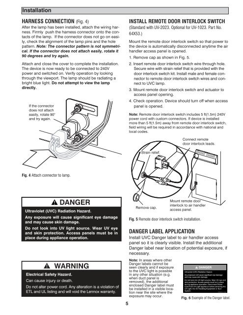
INSTALL REMOTE DOOR INTERLOCK SWITCH<br />
(Standard with UV-2023. Optional for UV-1023. Part No.<br />
64X53.)<br />
Mount the remote door interlock switch so that power to<br />
the device is automatically disconnected anytime the air<br />
handler access panel is opened.<br />
1. Remove cap as shown in Fig. 5.<br />
2. Insert remote door interlock switch wire through hole.<br />
Secure wire with strain relief that is provided with the<br />
door interlock switch kit. Install male and female connector<br />
to remote door interlock switch wires and connect<br />
to UVC lamp.<br />
3. Mount remote door interlock switch and actuator to<br />
access panel opening.<br />
4. Check operation. Device should turn off when access<br />
panel is opened.<br />
Note: Remote door interlock switch includes 5 ft(1.5m) 240V<br />
power cord with custom connectors. If device is installed<br />
more than 5 ft(1.5m) away from remote door interlock switch,<br />
field wiring will be required in accordance with national and<br />
local codes.<br />
Connect remote<br />
door interlock leads.<br />
Strain relief.<br />
Fig. 4 Attach connector to lamp.<br />
DANGER<br />
Ultraviolet (UVC) Radiation Hazard.<br />
Any exposure will cause significant eye damage<br />
and may cause skin damage.<br />
Do not look into UV light source. Wear UV eye<br />
and skin protection. Access panels must be in<br />
place during appliance operation.<br />
WARNING<br />
Electrical Safety Hazard.<br />
Can cause injury or death.<br />
Do not alter power cord. Any alteration is a violation of<br />
ETL and UL listing and will void the <strong>Lennox</strong> warranty.<br />
5<br />
Remove cap.<br />
Fig. 5 Remote door interlock switch installation.<br />
DANGER LABEL APPLICATION<br />
Install UVC Danger label to air handler access<br />
panel so it is clearly visible. Install the additional<br />
Danger label near location of potential exposure, if<br />
necessary.<br />
Note: In areas where other<br />
Danger labels cannot be<br />
seen clearly and if exposure<br />
to the UVC light is possible<br />
in any other situation (e.g.<br />
when duct panel is<br />
removed), the additional<br />
enclosed Danger label must<br />
be installed in a visible location<br />
near the site where the<br />
exposure may occur.<br />
Mount remote door<br />
interlock to air handler<br />
access panel.<br />
DANGER<br />
Ultraviolet (UVC) Radiation Hazard.<br />
Any exposure will cause significant eye damage<br />
and may cause skin damage.<br />
Do not look into UV light source. Wear UV eye and<br />
skin protection. Access panels must be in place<br />
during appliance operation. Disconnect Power<br />
Cord from UV Light appliance before servicing the<br />
UV Light, the Air Handling Equipment or Duct<br />
System.<br />
212790-00 Rev. 1A 7/03<br />
Fig. 6 Example of the Danger label.


