Colorado - bei Karmann Mobil
Colorado - bei Karmann Mobil
Colorado - bei Karmann Mobil

Create successful ePaper yourself
Turn your PDF publications into a flip-book with our unique Google optimized e-Paper software.
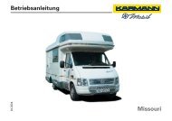
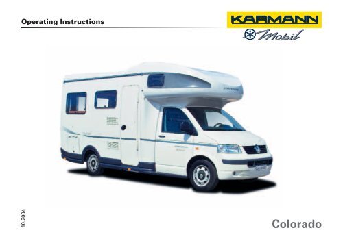
Operating Instructions<br />
10.2004<br />
<strong>Colorado</strong>
Congratulations on your new <strong>Karmann</strong> <strong>Mobil</strong>e Home<br />
You have made the right decision, for <strong>Karmann</strong> has been building mobile homes for more than<br />
100 years. That means quality and reliability. And that is why <strong>Karmann</strong> is mentioned in the same breath as the best<br />
automobile manufacturers.<br />
We don't simply put any body on any chassis. On the contrary: safe handling can only be achieved if a first-class<br />
chassis from an excellent manufacturer is given an body which is perfectly adapted to it, a body from <strong>Karmann</strong>-<strong>Mobil</strong>.<br />
And what about service and replacement parts? Who wants to get stuck somewhere with a broken windscreen?<br />
A network of selected partners will make sure that fast help is available everywhere.<br />
<strong>Karmann</strong>-<strong>Mobil</strong> - that means quality, reliability and pleasure for many years ahead.<br />
We wish you a safe and happy journey.<br />
Yours sincerely <strong>Karmann</strong>-<strong>Mobil</strong> Vertriebs GmbH
ON-BOARD LITERATURE<br />
This additional literature contains important<br />
notes for operation and care of your mobile<br />
home as well as for use of its equipment.<br />
The many practical tips included in it are<br />
intended to make it easy for you to use your<br />
<strong>Karmann</strong> mobile home in the best way<br />
possible, safely and in an environmentallyfriendly<br />
way.<br />
In the interests of safety, please read the<br />
information regarding use of the gas<br />
equipment and the 230 Volt vehicle electrical<br />
supply system.<br />
You will find all general information regarding<br />
operation and handling of your vehicle in the<br />
operating instructions for the basic chassis.<br />
Caution<br />
Sections introduced by the word<br />
"Caution" and with a coloured<br />
background indicate possible sources of<br />
accident and injury.<br />
Sections with this symbol written in<br />
italics offer important information on<br />
environmental protection<br />
If you wish to equip your mobile home with<br />
special accessories such as bicycle, ski or<br />
surfboard racks or awnings, you should take<br />
advantage of the range on offer from<br />
<strong>Karmann</strong> <strong>Mobil</strong> dealers.<br />
These accessories have been especially<br />
developed for your vehicle and tested for<br />
reliability, safety and suitability - please also<br />
note the instructions regarding the basic<br />
chassis.<br />
Detailed assembly and operation instructions<br />
are of course included with these<br />
accessories.
CONTENTS<br />
Overview of equipment<br />
<strong>Colorado</strong> 550 Exterior 1-1 Interior 1-2<br />
<strong>Colorado</strong> 600 Exterior 1-3 Interior 1-4<br />
<strong>Colorado</strong> 650 Exterior 1-5 Interior 1-6<br />
<strong>Colorado</strong> 660 Exterior 1-7 Interior 1-8<br />
<strong>Colorado</strong> 625 TI Exterior 1-9 Interior 1-10<br />
<strong>Colorado</strong> 655 TI Exterior 1-11 Interior 1-12<br />
<strong>Colorado</strong> 665 TI Exterior 1-13 Interior 1-14<br />
<strong>Colorado</strong> 675 TI Exterior 1-15 Interior 1-16<br />
Before travelling<br />
Tips for commissioning 2-1<br />
Checklist for the roadworthiness<br />
of your mobile home 2-3<br />
Doors & Windows, Storage space<br />
Keys 3-1<br />
Lock for body door 3-1<br />
Locks for external storage boxes 3-2<br />
Entry 3-2<br />
Opening window 3-3<br />
Sliding window 3-3<br />
Shade and insect blinds 3-4<br />
Toilet roof hatch (if present) 3-5<br />
HEKI1 tilt and slide roof 3-6<br />
Mini HEKI roof hatch 3-7<br />
Furniture<br />
Body table seating group 4-1<br />
Rear table seating group<br />
(<strong>Colorado</strong> 600, 660) 4-2<br />
Body seating group seat belts 4-2<br />
Safety belts in the rear 4-2<br />
Sleeping in your mobile home 4-3<br />
Alcoves 4-4<br />
Child safety device in the alcove 4-4<br />
Round seating group <strong>Colorado</strong> 650 4-5<br />
Rotating drivers cab seats 4-6<br />
Cupboards 4-6<br />
Gas equipment<br />
Gas supply 5-1<br />
Heating and hot water supply 5-3<br />
Gas cooker 5-6<br />
Fridge 5-8<br />
Electrical equipment<br />
On-board control panel 6-1<br />
Fuses/safety devices in the living space 6-2<br />
Automatic circuit breaker 230 V 6-2<br />
Charger and battery 6-2<br />
Living space lights 6-4<br />
Rear lights 6-5<br />
Water and waste disposal<br />
Fresh water supply 7-1<br />
Sink with mixer tap 7-3<br />
Washbasin and shower 7-4<br />
Toilet 7-4<br />
Sewage tank 7-6<br />
Waste water tank 7-7<br />
Accessories<br />
Carrier rails 8-1<br />
cycle racks 8-1<br />
Chassis<br />
Low-frame chassis 9-1<br />
Care of the vehicle<br />
Interior 10-1<br />
Exterior 10-2<br />
Notes on operation<br />
Winter 11-1<br />
Immobilisation of vehicle in winter 11-2<br />
Faultfinding and elimination<br />
Gas equipment 12-1<br />
Heating/hot water 12-2<br />
Power supply 12-4<br />
Water supply 12-6<br />
Technical data<br />
Weights 13-1<br />
Dimensions 13-2<br />
Fuel consumption 13-3<br />
List of terms 14-1
1-1<br />
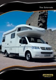
EQUIPMENT OVERVIEW <strong>Colorado</strong> 550<br />
Exterior<br />
1<br />
Fuel filler cap<br />
6<br />
Outside flap<br />
for gas<br />
cylinder box<br />
Page 5-1<br />
3<br />
2<br />
Discharge<br />
flap for<br />
sewage tank<br />
Page 7-6<br />
7 230 V<br />
connector<br />
Page 6-2<br />
1 6 7 5 2<br />
3<br />
4<br />
Waste water<br />
discharge tap/<br />
Discharge<br />
fitting<br />
Page 7-7<br />
Air outlet for<br />
heating<br />
system<br />
8 Refrigerator<br />
air vent<br />
Page 5-8, 10-2<br />
8<br />
5<br />
Fresh water<br />
filler nozzle<br />
Page 7-1<br />
4
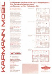
EQUIPMENT OVERVIEW <strong>Colorado</strong> 550 1-2<br />
Interior<br />
Electrical equipment<br />
Page<br />
Living area<br />
Page<br />
1 Automatic charger 6-2<br />
1a Body battery 6-2<br />
2 Bord-Control Panel 6-1<br />
3 Netzmatik (automatic<br />
circuit breaker 230 V) 6-2<br />
4 Fuses 6-1, 6-2<br />
Gas equipment<br />
5 Shutoff valve 5-1<br />
Supply and disposal<br />
6 Fresh water tank 7-1<br />
7 Waste water tank 7-7<br />
8 Gas cylinders 5-1<br />
9 Combi-device Heating/Hot water 5-3<br />
10 Truma valve, electrical 5-4<br />
11 Water pump 7-2<br />
12 Discharge tap, waste water 7-7<br />
13 Seating group<br />
14 Table 4-1<br />
15 Sleeping quarters 4-3<br />
16 Wardrobe<br />
17 Kitchen with<br />
- Gas cooker 5-6<br />
- Sink 7-3<br />
- Refrigerator 5-8<br />
Bathroom and WC<br />
18 Toilet 7-4<br />
19 Washbasin 7-4<br />
20 Shower 7-4<br />
1a<br />
4<br />
3<br />
13<br />
8<br />
15<br />
14<br />
11<br />
6<br />
13<br />
1<br />
2<br />
17<br />
5<br />
10<br />
20<br />
9<br />
18<br />
12<br />
19<br />
22<br />
This list gives you an initial overview of the important components in your mobile home.<br />
More detailed information can be found in the relevant chapters.<br />
7<br />
16
1-3<br />
EQUIPMENT OVERVIEW <strong>Colorado</strong> 600<br />
Exterior<br />
4<br />
1<br />
Fuel filler cap<br />
6<br />
Outside flap<br />
for gas<br />
cylinder box<br />
Page 5-1<br />
2<br />
Discharge<br />
flap for<br />
sewage tank<br />
Page 7-6<br />
7 230 V<br />
connector<br />
Page 6-2<br />
1 2 7<br />
5 6<br />
3<br />
3<br />
Waste water<br />
discharge tap/<br />
Discharge<br />
fitting<br />
Page 7-7<br />
8 Refrigerator<br />
air vent<br />
Page 5-8, 10-2<br />
4<br />
Air outlet for<br />
heating<br />
system<br />
5<br />
Fresh water<br />
filler nozzle<br />
Page 7-1<br />
8
EQUIPMENT OVERVIEW <strong>Colorado</strong> 600 1-4<br />
Interior<br />
Electrical equipment<br />
Page<br />
1 Automatic charger 6-2<br />
1a Body battery 6-2<br />
2 Bord-Control Panel 6-1<br />
3 Netzmatik (automatic<br />
circuit breaker 230 V) 6-2<br />
4 Fuses 6-1, 6-2<br />
Gas equipment<br />
5 Shutoff valve 5-1<br />
Supply and disposal<br />
6 Truma valve, electrical 5-4<br />
7 Fresh water tank 7-1<br />
8 Waste water tank 7-7<br />
9 Discharge tap, waste water 7-7<br />
10 Gas cylinders 5-1<br />
11 Combi-device Heating/Hot water 5-3<br />
12 Water pump 7-2<br />
Living area<br />
Page<br />
13 Seating group<br />
14 Table 4-2<br />
15 Sleeping quarters 4-3<br />
16 Wardrobe<br />
17 Kitchen with<br />
- Gas cooker 5-6<br />
- Sink 7-3<br />
- Refrigerator 5-8<br />
Bathroom and WC<br />
18 Toilet 7-4<br />
19 Washbasin 7-4<br />
20 Shower 7-4<br />
1a<br />
4 1<br />
3 15<br />
20<br />
2<br />
19<br />
18<br />
17<br />
6<br />
16<br />
8<br />
11<br />
14<br />
5<br />
12<br />
7<br />
10<br />
This list gives you an initial overview of the important components in your mobile home.<br />
More detailed information can be found in the relevant chapters.<br />
9 15 13
1-5<br />
EQUIPMENT OVERVIEW <strong>Colorado</strong> 650<br />
Exterior<br />
1<br />
Fuel filler cap<br />
6<br />
Outside flap<br />
for gas<br />
cylinder box<br />
Page 5-1<br />
2<br />
Discharge<br />
flap for<br />
sewage tank<br />
Page 7-6<br />
7 230 V<br />
connector<br />
Page 6-2<br />
1 6 7 5 9 3 2<br />
3<br />
Waste water<br />
discharge tap/<br />
Discharge<br />
fitting<br />
Page 7-7<br />
8 Refrigerator<br />
air vent<br />
Page 5-8, 10-2<br />
4<br />
Air outlet for<br />
heating<br />
system<br />
9<br />
Storage space<br />
flap<br />
8<br />
5<br />
Fresh water<br />
filler nozzle<br />
Page 7-1<br />
4
EQUIPMENT OVERVIEW <strong>Colorado</strong> 650 1-6<br />
Interior<br />
Electrical equipment<br />
Page<br />
Living area<br />
Page<br />
1 Automatic charger 6-2<br />
1a Body battery 6-2<br />
2 Bord-Control Panel 6-1<br />
3 Netzmatik (automatic<br />
circuit breaker 230 V) 6-2<br />
4 Fuses 6-1, 6-2<br />
Gas equipment<br />
5 Shutoff valve 5-1<br />
Supply and disposal<br />
6 Truma valve, electrical 5-4<br />
7 Fresh water tank 7-1<br />
8 Waste water tank 7-7<br />
9 Discharge tap, waste water 7-7<br />
10 Gas cylinders 5-1<br />
11 Combi-device Heating/Hot water 5-3<br />
12 Water pump 7-2<br />
13 Seating group<br />
14 Table 4-1<br />
15 Sleeping quarters 4-3<br />
16 Wardrobe<br />
17 Kitchen with<br />
- Gas cooker 5-6<br />
- Sink 7-3<br />
- Refrigerator 5-8<br />
Bathroom and WC<br />
18 Toilet 7-4<br />
19 Washbasin 7-4<br />
20 Shower 7-4<br />
1a<br />
4<br />
3<br />
10<br />
13<br />
14<br />
12<br />
7<br />
13<br />
15<br />
1<br />
15<br />
17<br />
8<br />
5<br />
2<br />
9<br />
11<br />
This list gives you an initial overview of the important components in your mobile home.<br />
More detailed information can be found in the relevant chapters.<br />
20<br />
18<br />
19 6<br />
16
1-7<br />
EQUIPMENT OVERVIEW <strong>Colorado</strong> 660<br />
Exterior<br />
1<br />
Fuel filler cap<br />
6<br />
Outside flap<br />
for gas<br />
cylinder box<br />
Page 5-1<br />
2<br />
Discharge<br />
flap for<br />
sewage tank<br />
Page 7-6<br />
7 230 V<br />
connector<br />
Page 6-2<br />
1 7 5 2 6<br />
3<br />
3<br />
Waste water<br />
discharge tap/<br />
Discharge<br />
fitting<br />
Page 7-7<br />
8 Refrigerator<br />
air vent<br />
Page 5-8, 10-2<br />
4<br />
Air outlet for<br />
heating<br />
system<br />
5<br />
Fresh water<br />
filler nozzle<br />
Page 7-1<br />
8<br />
4
EQUIPMENT OVERVIEW <strong>Colorado</strong> 660 1-8<br />
Interior<br />
Electrical equipment<br />
Page<br />
Living area<br />
Page<br />
1 Automatic charger 6-2<br />
1a Body battery 6-2<br />
2 Bord-Control Panel 6-1<br />
3 Netzmatik (automatic<br />
circuit breaker 230 V) 6-2<br />
4 Fuses 6-1, 6-2<br />
Gas equipment<br />
5 Shutoff valve 5-1<br />
Supply and disposal<br />
6 Truma valve, electrical 5-4<br />
7 Fresh water tank 7-1<br />
8 Waste water tank 7-7<br />
9 Discharge tap, waste water 7-7<br />
10 Gas cylinders 5-1<br />
11 Combi-device Heating/Hot water 5-3<br />
12 Water pump 7-2<br />
13 Seating group<br />
14 Table 4-1<br />
15 Sleeping quarters 4-3<br />
16 Wardrobe<br />
17 Kitchen with<br />
- Gas cooker 5-6<br />
- Sink 7-3<br />
- Refrigerator 5-8<br />
Bathroom and WC<br />
18 Toilet 7-4<br />
19 Washbasin 7-4<br />
20 Shower 7-4<br />
21 Storage space flap, underfloor<br />
technical equipment area<br />
1a<br />
4<br />
3<br />
14<br />
13<br />
7<br />
18<br />
8<br />
19<br />
15<br />
1<br />
17<br />
5<br />
2<br />
6<br />
21<br />
20<br />
16<br />
11<br />
12<br />
15<br />
10<br />
This list gives you an initial overview of the important components in your mobile home.<br />
More detailed information can be found in the relevant chapters.<br />
13 9 14<br />
13
1-9<br />
EQUIPMENT OVERVIEW <strong>Colorado</strong> 625 TI<br />
Exterior<br />
1<br />
Fuel filler cap<br />
5<br />
Outside flap<br />
for gas<br />
cylinder box<br />
Page 5-1<br />
2<br />
Discharge<br />
flap for<br />
sewage tank<br />
Page 7-6<br />
6 230 V<br />
connector<br />
Page 6-2<br />
1<br />
6 4 5 8 2<br />
3<br />
Air outlet for<br />
heating<br />
system<br />
7 Refrigerator<br />
air vent<br />
Page 5-8, 10-2<br />
4<br />
Fresh water<br />
filler nozzle<br />
Page 7-1<br />
8<br />
Waste water<br />
discharge<br />
fitting<br />
Page 7-7<br />
7<br />
3
EQUIPMENT OVERVIEW <strong>Colorado</strong> 625 TI 1-10<br />
Interior<br />
Electrical equipment<br />
Page<br />
1 Automatic charger 6-2<br />
1a Body battery 6-2<br />
2 Bord-Control Panel 6-1<br />
3 Netzmatik (automatic<br />
circuit breaker 230 V) 6-2<br />
4 Fuses 6-1, 6-2<br />
Gas equipment<br />
5 Shutoff valve 5-1<br />
Supply and disposal<br />
6 Truma valve, electrical 5-4<br />
7 Fresh water tank 7-1<br />
8 Waste water tank 7-7<br />
9 Discharge tap, waste water 7-7<br />
10 Gas cylinders 5-1<br />
11 Combi-device Heating/Hot water 5-3<br />
12 Water pump 7-2<br />
Living area<br />
Page<br />
13 Seating group<br />
14 Table 4-1<br />
15 Sleeping quarters 4-3<br />
16 Wardrobe<br />
17 Kitchen with<br />
- Gas cooker 5-6<br />
- Sink 7-3<br />
- Refrigerator 5-8<br />
Bathroom and WC<br />
18 Toilet 7-4<br />
19 Washbasin 7-4<br />
20 Shower 7-4<br />
1a<br />
4 1<br />
3<br />
14<br />
12<br />
5<br />
13<br />
17<br />
7<br />
2<br />
10<br />
16<br />
8<br />
19<br />
6<br />
11<br />
9<br />
18<br />
15<br />
This list gives you an initial overview of the important components in your mobile home.<br />
More detailed information can be found in the relevant chapters.<br />
20
1-11<br />
EQUIPMENT OVERVIEW <strong>Colorado</strong> 655 TI<br />
Exterior<br />
1<br />
Fuel filler cap<br />
5<br />
Outside flap<br />
for gas<br />
cylinder box<br />
Page 5-1<br />
7<br />
2<br />
Discharge<br />
flap for<br />
sewage tank<br />
Page 7-6<br />
6 230 V<br />
connector<br />
Page 6-2<br />
1 6 4 8<br />
2<br />
3<br />
4<br />
Air outlet for<br />
heating<br />
system<br />
Fresh water<br />
filler nozzle<br />
Page 7-1<br />
7 Refrigerator<br />
air vent<br />
Page 5-8, 10-2<br />
8<br />
Waste water<br />
discharge<br />
fitting<br />
Page 7-7<br />
3<br />
5
EQUIPMENT OVERVIEW <strong>Colorado</strong> 655 TI 1-12<br />
Interior<br />
Electrical equipment<br />
Page<br />
1 Automatic charger 6-2<br />
1a Body battery 6-2<br />
2 Bord-Control Panel 6-1<br />
3 Netzmatik (automatic<br />
circuit breaker 230 V) 6-2<br />
4 Fuses 6-1, 6-2<br />
Gas equipment<br />
5 Shutoff valve 5-1<br />
Supply and disposal<br />
6 Truma valve, electrical 5-4<br />
7 Fresh water tank 7-1<br />
8 Waste water tank 7-7<br />
9 Discharge tap, waste water 7-7<br />
10 Gas cylinders 5-1<br />
11 Combi-device Heating/Hot water 5-3<br />
12 Water pump 7-2<br />
Living area<br />
Page<br />
13 Seating group<br />
14 Table 4-1<br />
15 Sleeping quarters 4-3<br />
16 Wardrobe<br />
17 Kitchen with<br />
- Gas cooker 5-5<br />
- Sink 7-3<br />
- Refrigerator 5-8<br />
Bathroom and WC<br />
18 Toilet 7-4<br />
19 Washbasin 7-4<br />
20 Shower 7-4<br />
1a<br />
4 1<br />
3<br />
13<br />
10<br />
14<br />
7<br />
2<br />
6<br />
17<br />
11<br />
5<br />
16<br />
12<br />
8<br />
9<br />
19<br />
18<br />
15<br />
This list gives you an initial overview of the important components in your mobile home.<br />
More detailed information can be found in the relevant chapters.<br />
20
1-13<br />
EQUIPMENT OVERVIEW <strong>Colorado</strong> 665 TI<br />
Exterior<br />
1<br />
Fuel filler cap<br />
5<br />
Outside flap<br />
for gas<br />
cylinder box<br />
Page 5-1<br />
2<br />
Discharge<br />
flap for<br />
sewage tank<br />
Page 7-6<br />
6 230 V<br />
connector<br />
Page 6-2<br />
3<br />
Air outlet for<br />
heating<br />
system<br />
7 Refrigerator<br />
air vent<br />
Page 5-8, 10-2<br />
1 6 4 2 8<br />
5<br />
4<br />
Fresh water<br />
filler nozzle<br />
Page 7-1<br />
8<br />
Waste water<br />
discharge<br />
fitting<br />
Page 7-7<br />
7<br />
3
EQUIPMENT OVERVIEW <strong>Colorado</strong> 665 TI 1-14<br />
Interior<br />
Electrical equipment<br />
Page<br />
Living area<br />
Page<br />
1 Automatic charger 6-2<br />
1a Body battery 6-2<br />
2 Bord-Control Panel 6-1<br />
3 Netzmatik (automatic<br />
circuit breaker 230 V) 6-2<br />
4 Fuses 6-1, 6-2<br />
Gas equipment<br />
5 Shutoff valve 5-1<br />
Supply and disposal<br />
6 Truma valve, electrical 5-4<br />
7 Fresh water tank 7-1<br />
8 Waste water tank 7-7<br />
9 Discharge tap, waste water 7-7<br />
10 Gas cylinders 5-1<br />
11 Combi-device Heating/Hot water 5-3<br />
12 Water pump 7-2<br />
13 Seating group<br />
14 Table 4-1<br />
15 Sleeping quarters 4-3<br />
16 Wardrobe<br />
17 Kitchen with<br />
- Gas cooker 5-6<br />
- Sink 7-3<br />
- Refrigerator 5-8<br />
Bathroom and WC<br />
18 Toilet 7-4<br />
19 Washbasin 7-4<br />
20 Shower 7-4<br />
1a<br />
4<br />
3<br />
14<br />
13<br />
7<br />
18<br />
19<br />
1<br />
5<br />
17<br />
2<br />
6<br />
8/9<br />
11<br />
20<br />
16<br />
12<br />
10<br />
15<br />
This list gives you an initial overview of the important components in your mobile home.<br />
More detailed information can be found in the relevant chapters.
1-15<br />
EQUIPMENT OVERVIEW <strong>Colorado</strong> 675 TI<br />
Exterior<br />
1<br />
Fuel filler cap<br />
5<br />
Outside flap<br />
for gas<br />
cylinder box<br />
Page 5-1<br />
2<br />
Discharge<br />
flap for<br />
sewage tank<br />
Page 7-6<br />
6 230 V<br />
connector<br />
Page 6-2<br />
3<br />
Air outlet for<br />
heating<br />
system<br />
7 Refrigerator<br />
air vent<br />
Page 5-8, 10-2<br />
1 5 6 4<br />
8<br />
4<br />
Fresh water<br />
filler nozzle<br />
Page 7-1<br />
8<br />
Waste water<br />
discharge<br />
fitting<br />
Page 7-7<br />
7<br />
2 3
EQUIPMENT OVERVIEW <strong>Colorado</strong> 675 TI 1-16<br />
Interior<br />
Electrical equipment<br />
Page<br />
Automatic charger 6-2<br />
1a Body battery 6-2<br />
2 Bord-Control Panel 6-1<br />
3 Netzmatik (automatic<br />
circuit breaker 230 V) 6-2<br />
4 Fuses 6-1, 6-2<br />
Gas equipment<br />
5 Shutoff valve 5-1<br />
Supply and disposal<br />
6 Truma valve, electrical 5-4<br />
7 Fresh water tank 7-1<br />
8 Waste water tank 7-7<br />
9 Discharge tap, waste water 7-7<br />
10 Gas cylinders 5-1<br />
11 Combi-device Heating/Hot water 5-3<br />
12 Water pump 7-2<br />
Living area<br />
Page<br />
13 Seating group<br />
14 Table 4-1<br />
15 Sleeping quarters 4-3<br />
16 Wardrobe<br />
17 Kitchen with<br />
- Gas cooker 5-6<br />
- Sink 7-3<br />
- Refrigerator 5-8<br />
Bathroom and WC<br />
18 Toilet 7-4<br />
19 Washbasin 7-4<br />
20 Shower 7-4<br />
1a<br />
4 1<br />
3<br />
13<br />
10<br />
5<br />
14<br />
17<br />
12<br />
13<br />
2<br />
7<br />
6<br />
8/9<br />
11<br />
16<br />
19<br />
15 18<br />
This list gives you an initial overview of the important components in your mobile home.<br />
More detailed information can be found in the relevant chapters.<br />
20
2-1<br />
BEFORE STARTING OFF<br />
Tips on commissioning<br />
Do not use your new mobile home<br />
immediately for a long holiday trip. A<br />
weekend trip of maximum 100 kilometres is<br />
enough for the first time.<br />
Drive slowly and carefully. Observe the rules<br />
for running in the basic vehicle.<br />
Dimensions<br />
Your mobile home may be a larger vehicle<br />
than you are used to driving. Get used to the<br />
special dimensions of the vehicle slowly<br />
(listed in the technical data in the annex to<br />
these operating instructions).<br />
Take particular care when:<br />
driving through gates, over bridges, under<br />
arched tunnels or archways, into car parks.<br />
Also watch out for overhanging branches,<br />
petrol station roofs etc.<br />
Instruments<br />
Get to know the different instruments. Apart<br />
from the attached operating instructions for<br />
the chassis and driver's cab you will find<br />
detailed descriptions of:<br />
Refrigerator 230 V/12V/Gas<br />
Heating/Water boiler<br />
Gas cooker<br />
Toilet<br />
Automatic charger<br />
Water pump<br />
Although the function of all the equipment in<br />
your mobile home were certainly<br />
demonstrated to you when you bought it, you<br />
should read through the operating<br />
instructions again in detail. They contain<br />
useful advice on what to do when faults<br />
occur, care of the vehicle etc.<br />
Tow bar<br />
If you use a tow bar you should ensure<br />
without fail that you do not exceed the<br />
permitted load. If you wish to tow a trailer -<br />
no matter of what size - please note the<br />
relevant legal regulations.<br />
Loading<br />
The maximum technically permissible overall<br />
weight stated in the vehicle documents may<br />
not be exceeded by excessive loading under<br />
any circumstances.<br />
Please consider that any built-in accessories<br />
may reduce the possible loading. When<br />
loading the vehicle, please also consider the<br />
weight of any passengers.<br />
Incorrect tyre pressures and overloading can<br />
lead to burst tyres.<br />
Make sure that the permissible axle loads<br />
stated in the vehicle documents are not<br />
exceeded.
BEFORE STARTING OFF 2-2<br />
Tips on commissioning<br />
Correct loading of your mobile home<br />
As a basic principle, the heaviest items<br />
should be as near the floor as possible.<br />
Therefore store heavy objects in this area.<br />
Make sure the load is balanced between the<br />
left and right sides.<br />
Objects in the top cupboards should also be<br />
protected against slipping.<br />
Do not exceed the maximum load for the<br />
cycle rack (special accessory) and the<br />
permissible roof load of 150 kg.<br />
Please make sure that cycles are well<br />
secured and tied. After driving for a short<br />
distance, stop and check that nothing has<br />
moved.<br />
In the interests of safety you should have the<br />
vehicle and passengers weighed before the<br />
start of the journey.<br />
Wing mirrors<br />
You will find large wing mirrors on both sides<br />
of your vehicle. Before starting out on your<br />
first journey you should adjust these and if<br />
necessary correct them after a short distance.<br />
Travelling and overnight stops<br />
In general it is allowed to make overnight<br />
stops in car parks in Germany - at least for<br />
one night. However, camping tables, chairs<br />
etc. or other items should not be placed<br />
outside to give the impression of "camping<br />
out". Specialist magazines and camping<br />
guides contain useful information, or you can<br />
contact the CIVD club to find out about<br />
districts which welcome caravans and<br />
mobile homes, rules for waste water disposal<br />
etc. Different rules apply abroad with regard<br />
to mobile homes and overnight stops.<br />
Find out about the following before starting<br />
your journey:<br />
necessary documents<br />
legal regulations concerning maximum<br />
speeds and prohibitions on overtaking<br />
electrical supply standard<br />
where to make overnight stops<br />
The ADAC can also supply information with<br />
regard to the relevant regulations concerning<br />
overnight stops outside camping sites, speed<br />
limits etc. in the country you plan to visit.
2-3<br />
BEFORE STARTING YOUR JOURNEY<br />
Safety checklist<br />
To make sure that your <strong>Karmann</strong> mobile<br />
home is always safe, you should check<br />
certain points before the start of every<br />
journey. You can find more detailed<br />
information about this in these operating<br />
instructions:<br />
Retract entry step (illuminated display)<br />
Close and lock all exterior flaps<br />
Close the body door<br />
Close and lock the opening<br />
window<br />
Close the roof hatch<br />
Close drawers and cupboards<br />
Close door to bathroom and WC<br />
Close refrigerator door<br />
Secure TV aerial, if installed<br />
Check luggage for secure fixing<br />
Store away objects lying around on<br />
shelves, tables etc.<br />
Close shutoff valves for gas equipment,<br />
if it is not <strong>bei</strong>ng used<br />
Free the roof of ice and snow in the winter<br />
Check the battery voltage of the vehicle<br />
and auxiliary battery at the control panel,<br />
particularly in winter (see Page 6-1).<br />
Open all blinds before starting the journey.<br />
Check the following on the basis vehicle<br />
according to the T 5 operating instructions:<br />
Tire pressure<br />
Vehicle lights<br />
Oil level<br />
Coolant level<br />
Travelling in the <strong>Karmann</strong> mobile home<br />
Even if you are used to driving mobile homes,<br />
you must remember when travelling that,<br />
because of the chassis, a mobile home is<br />
virtually a small truck which requires<br />
particular care as regards driving and<br />
handling characteristics<br />
Because of its relatively long projection<br />
behind the rear axle, the back end of the<br />
vehicle can break away.<br />
When driving up steep slopes or ramps<br />
make sure that the back end does not hit<br />
the ground.<br />
Avoid sudden braking if possible.<br />
Make sure that any passengers sitting in<br />
the rear of the vehicle are wearing their<br />
seatbelts and that they do not leave their<br />
seats.<br />
Only allow people to travel in the vehicle<br />
in the seat provided with seatbelts.<br />
Even after short interruptions to the<br />
journey, always make sure that the entry<br />
step is retracted.
DOORS, WINDOWS, STORAGE SPACE 3-1<br />
Keys<br />
Body door lock<br />
A<br />
A<br />
C<br />
A<br />
B<br />
Key A Ignition, driver and passenger door,<br />
fuel flap<br />
Key B body door, external storage box,<br />
sewage tank<br />
Note<br />
Depending on equipment, your <strong>Karmann</strong><br />
mobile home may also be supplied with other<br />
keys, e.g. for top box.<br />
Caution<br />
Before starting your journey, ensure that<br />
the body door is locked.<br />
B<br />
Unlocking the body door<br />
Place the key in the lock and turn to the right<br />
until the lock opens, return key to original<br />
position and remove. Unlatch the door by<br />
pulling back the handle and pressing against<br />
the door at the same time. Then open the<br />
door. Do not try to open the door from the<br />
inside and the outside at the same time.<br />
Opening and closing the body door from the<br />
inside<br />
To open the door, pull handle A. To lock the<br />
door, press knob B. To close the door, pull on<br />
handle C, until it latches in the second<br />
position.<br />
The insect curtain door is secured by toggle<br />
D on the body door. If you want to use the<br />
insect curtain separately, turn toggle D until it<br />
B<br />
is in the vertical position. In order to ensure<br />
effective protection against insects you<br />
should keep the curtain closed when the<br />
body door is open.<br />
Doorstop mechanisms for living and storage<br />
space doors<br />
In order to hold the body and storage space<br />
doors open, hook loop A into clamp B.
3-2<br />
DOORS, WINDOWS, STORAGE SPACE<br />
Locks for outside storage boxes<br />
Entry<br />
The outside storage boxes are all supplied<br />
with identical locks.<br />
Unlocking the flap<br />
Insert the key in the lock and turn to the right<br />
until the lock opens. Return the key to the<br />
original position and retract. Open the flap by<br />
pulling the handle.<br />
Locking the flap<br />
Insert the key in the lock and turn to the left<br />
until it locks. Return the key to the original<br />
position and retract.<br />
Caution<br />
Before starting your journey check<br />
that all outside flaps are closed<br />
and locked.<br />
Electrically-operated entry step<br />
The step can be extended or retracted by<br />
means of the switch in the entrance area.<br />
Caution<br />
Make sure that the step is always<br />
retracted during travel.<br />
When the ignition is switched on a<br />
warning lamp lights up in the<br />
instrument panel if the step is not<br />
retracted.
DOORS, WINDOWS, STORAGE SPACE 3-3<br />
Opening windows<br />
Sliding window<br />
A<br />
A<br />
B<br />
B<br />
Open and close windows<br />
In order to open the window, unlock the hook<br />
by pushing the locking button. The hooks at<br />
the side have to be horizontal, the hook on<br />
the lower side of the window must be<br />
vertical.<br />
The window is now open and can be latched<br />
into a variety of positions. In order to release<br />
the catch, lift the window slightly.<br />
Note<br />
In order to avoid damage, windows must not<br />
be open during travel. Please note the<br />
instructions regarding vehicle care (10-1).<br />
In extremely humid conditions, the space<br />
between the panes may mist up. This<br />
disappears again in dry weather.<br />
A<br />
To open the sliding window, first push locking<br />
rod A upwards. Push the two halves of<br />
handle B together in order to slide the<br />
window open.
3-4<br />
DOORS, WINDOWS, STORAGE SPACE<br />
Shade and insect blinds<br />
All windows are provided with a shade and<br />
insect blind. The illustration shows both<br />
blinds in half-open position. Both blinds can<br />
be pushed up and down together or<br />
separately.<br />
Shade blind<br />
The shade blind is pulled from the bottom to<br />
the top.<br />
The blind is adjustable and can be fixed in<br />
various positions.<br />
Insect blind<br />
Pull the insect blind from the top to the<br />
bottom.<br />
The handle is hooked into the handle of the<br />
shade blind and can be fixed in any position<br />
together with the shade blind.<br />
Caution<br />
Always pull up the shade blind<br />
completely before loosening the<br />
connection between insect and shade<br />
blind. This prevents the insect blind from<br />
shooting up in an uncontrolled way,<br />
which could cause injury.<br />
No blinds may be closed during travel!
DOORS, WINDOWS, STORAGE SPACE 3-5<br />
Roof hatch (not in all models)<br />
Before opening the roof hatch, first open the<br />
insect grille. In order to push up (and close)<br />
the hatch, handle lock A must be pressed in.<br />
The roof hatch can be closed at each side.<br />
The insect grille can be removed for<br />
cleaning. Pull down grille and pull off.<br />
Shade blind<br />
To darken the room, hook blind B into the<br />
holder on the handle of frame C.<br />
Notes<br />
In order to ensure a sufficient supply of<br />
oxygen at all times, your mobile home is<br />
supplied with automatic ventilation.<br />
However, in order to avoid condensation,<br />
it is important to air the inside of the<br />
vehicle and living space at regular<br />
intervals.<br />
Air your mobile home in the summer in<br />
order to avoid build-up of heat.<br />
Free the roof hatch of snow in winter in<br />
order to prevent water entering though<br />
the ventilation grille.<br />
Roof hatches must be closed during travel<br />
in order to prevent damage.
3-6<br />
DOORS, WINDOWS, STORAGE SPACE<br />
Heki 3 lift and tilt hatch<br />
Opening and closing pane<br />
When winding the handle to open, only wind<br />
until resistance can be felt. The angle of<br />
opening is max. 70°.<br />
When winding the handle to close, turn a<br />
further 2-3 times through a complete rotation<br />
(when the glass roof is already closed) in<br />
order to lock completely. Check lock by<br />
attempting to raise by hand.<br />
Operation of blind<br />
Closing: Take recess of finishing bar (without<br />
rocker/shade) and latch into opposite<br />
finishing bar with rocker.<br />
Opening: Push joined finishing bars into the<br />
shade position. Press the rocker and push<br />
back the blind with the other hand (do not<br />
leave go of shade).<br />
Adjustment: Push joined finishing bars into<br />
the desired position.<br />
Safety instructions<br />
Do not step on the acrylic glass<br />
Close the hatch completely before starting<br />
you journey<br />
Close the hatch before leaving the vehicle<br />
(risk of burglary or rain)<br />
Do not open in strong winds or rain<br />
Before opening, remove ice, snow leaves<br />
or any other similar items<br />
Do not use pressure washers, solvents or<br />
cleaning materials containing alcohol.<br />
Caution<br />
In strong sunlight the shade blind may<br />
only be closed 2/3 (plastic parts may be<br />
damaged if heat builds up between the<br />
blind and the glass).<br />
Blinds may not be closed during travel!
DOORS, WINDOWS, STORAGE SPACE 3-7<br />
Mini lift and tilt roof hatch<br />
B<br />
A<br />
D<br />
Opening and closing<br />
To open the mini hatch, first press button A,<br />
in order to free the bar. Pushing bar B allows<br />
the hatch to be opened in three positions. In<br />
the central position the bar can be fixed with<br />
slider C.<br />
To lock the hatch securely in the driving or<br />
rest position, the bar must latch in behind<br />
button A.<br />
Operation of blind / insect grille<br />
The mini hatch has a shade blind and an<br />
insect grille. In order to darken, take the<br />
closing bar of the blind and allow it to latch in<br />
the opposite bar of the insect grille. Now<br />
blind and insect grille can be brought into any<br />
desired intermediate position.<br />
To open, push the joined bars in the shade<br />
direction. Separate the bars by pushing rocker<br />
D with one hand and pushing the blind back<br />
with the other hand. Do not allow the blind to<br />
shoot back uncontrolled.<br />
Safety instructions<br />
Do not step on the acrylic glass<br />
Close the hatch completely before starting<br />
you journey<br />
Close the hatch before leaving the vehicle<br />
(risk of burglary or rain)<br />
Do not open in strong winds or rain<br />
Before opening, remove ice, snow leaves<br />
or any other similar items<br />
Do not use pressure washers, solvents or<br />
cleaning materials containing alcohol.<br />
Caution<br />
In strong sunlight the shade blind may<br />
only be closed 2/3 (plastic parts may be<br />
damaged if heat builds up between the<br />
blind and the glass).<br />
Blinds may not be closed during travel!
LIVING ACCOMMODATION 4-1<br />
Table in seating group (<strong>Colorado</strong> 550, 650, 660, 625 TI, 655 TI, 675 TI)<br />
A<br />
Lower tabletop<br />
Lift the table slightly at the front edge. Pull<br />
the table leg downwards and hinge it<br />
backwards. then lift the tabletop out of the<br />
guide rail and lay it on the bench rails.<br />
In order to return the table to its original<br />
position, click it into the guide rail and hinge<br />
the table leg down.<br />
Caution<br />
Make sure that the table is correctly<br />
clicked in. If so, red knob A projects.<br />
Extending tabletop<br />
The <strong>Colorado</strong> 650 and the 655TI has an<br />
extending tabletop in the found seating<br />
group. In order to pull out the table, lift the<br />
tabletop slightly and pull it back to the stop.<br />
The extra leaf for the table is on the floor of<br />
the wardrobe.<br />
Caution<br />
Push in the table during travel and<br />
secure the extra leaf in the holder in the<br />
wardrobe.
4-2<br />
LIVING ACCOMMODATION<br />
Table in the rear seating group<br />
Seat belts in the body seating group Safety belts in the rear<br />
A<br />
Adjusting the table height<br />
To adjust the height, push the lever under the<br />
table surface to the left.<br />
Push strongly against the tabletop at the<br />
column location in order to lower the table.<br />
Lock at the desired height by pressing the<br />
lever to the right.<br />
If the lever is again pressed to the left, the<br />
tabletop will automatically return to its<br />
original position by means of a gas pressure<br />
spring. Support the tabletop with one hand in<br />
order to prevent it from coming up suddenly.<br />
Use knurled screw A in order to free the<br />
tabletop for rotation and to lock it again.<br />
Body seating group<br />
The seating group is equipped with two<br />
three-point automatic seat belts in the<br />
direction of travel as standard. Lap belts<br />
against the direction of travel are available<br />
as standard.<br />
Note<br />
Seat belts may only be installed by a<br />
specialist dealer.<br />
The safety belts in the rear seating group are<br />
fixed to a rail on the side walls under the<br />
upholstery.<br />
Note<br />
A maximum of two pairs of belts can be<br />
installed on each bench. Use an authorised<br />
installer.
Sleeping arrangements in the <strong>Karmann</strong> mobile home<br />
LIVING ACCOMMODATION 4-3<br />
<strong>Colorado</strong> 550, 675 TI<br />
additional cushions<br />
backrests<br />
seat cushions<br />
seat cushions<br />
backrests<br />
additional cushions<br />
additional cushions<br />
additional cushions additional cushions<br />
<strong>Colorado</strong> 600, 660<br />
backrests<br />
seat cushions<br />
seat cushions<br />
backrests<br />
additional cushions<br />
<strong>Colorado</strong> 650<br />
backrests<br />
additional<br />
cushions<br />
seat<br />
cushions<br />
seat<br />
cushions<br />
seat<br />
cushions<br />
Sitzpolster<br />
seat cushions<br />
backrests<br />
backrests<br />
additional cushions<br />
<strong>Colorado</strong> 655 TI Additional bed<br />
seat cushions<br />
backrests<br />
seat cushions<br />
shoulder cushions<br />
backrests<br />
additional cushions<br />
In order to make a bed from the seating<br />
groups in the <strong>Colorado</strong> models, first lower<br />
the tabletop as described on pages 4-1<br />
and 4-2. The bed surface is formed of the<br />
backrests and seat cushions.<br />
Additional cushions can be taken from the<br />
alcove or the wardrobe.
4-4<br />
FURNITURE<br />
Alcove<br />
Child safety in the alcove<br />
A<br />
A<br />
In order to make access to the driver's cab<br />
easier, the bed in the alcove can be hinged<br />
up. The bed can remain in this position during<br />
travel.<br />
Alcove ladder<br />
The bed in the alcove is reached via the<br />
ladder.<br />
The child safety anti-fall barriers, to be used<br />
for example while children are asleep, is<br />
under the mattress in the alcove. They are<br />
simple inserted into holder B on both sides.<br />
Note<br />
Lock the child safety device during travel in<br />
order to ensure that the ladder does not fall<br />
down.
FURNITURE 4-5<br />
Round seating group <strong>Colorado</strong> 650<br />
Rearrangement of the seating group<br />
Side seating group and lenghtways bench of<br />
the <strong>Colorado</strong> 650 can be extended to form a<br />
round seating unit. Remove the seat cushion<br />
of the lenghtways bench. Take the seat plank<br />
out of wardrobe and put it between side<br />
seating group and lenghtways bench.The<br />
reinforced side of the seat plank is located at<br />
the lenghtways bench.Pull the cushion of the<br />
side seating bench about 5 cm onto seat<br />
plank.<br />
The backrest net for the back cushion is<br />
located under the matress in the alcove or in<br />
the wardrobe. Click the lower rod into the<br />
provided clips. Hang the other rod into the<br />
upper holders. Complete the round seating<br />
unit with the additional cushions.
4-6<br />
FURNITURE<br />
Rotating driver's cab seats<br />
Cupboards<br />
A<br />
C<br />
B<br />
Models <strong>Colorado</strong> 660, 625 TI, 655 TI and 665 TI<br />
are provided with a seating group which is<br />
completed by the seats in the driver's cab. In<br />
order to rotate the seats, first push Lever A<br />
into its highest position. Slide them as far<br />
forward as possible using stirrup B. Pull lever<br />
C upwards and rotate the seat.<br />
Caution<br />
The handbrake must not be on while the<br />
seat is <strong>bei</strong>ng rotated, as this can lead to<br />
damage of the handbrake lever.<br />
Pushlock<br />
All top and bottom cupboards are provided<br />
with pushlocks which prevent the cupboards<br />
from opening of their own accord during the<br />
journey.<br />
Locking<br />
Close the cupboard flaps and drawers and<br />
press the locking knob inwards. Make sure<br />
that the knob remains in the pushed-in<br />
position: the pushlock is then locked.<br />
Opening<br />
Press the locking knob in order to open the<br />
cupboard flaps and drawers. The knob<br />
springs outwards and the flaps and drawers<br />
can be opened.<br />
Caution<br />
Before starting each journey made sure<br />
that all flaps and drawers are closed and<br />
locked. Secure the items stored in<br />
cupboards and drawers against slipping<br />
in order to avoid damage.
GAS INSTALLATION 5-1<br />
Gas Supply<br />
Gas cylinder box<br />
You will find the position of the relevant gas<br />
cylinder box on the equipment pages from<br />
1-1. The gas cylinder box accommodates two<br />
11 kg gas cylinders. Both gas cylinders must<br />
always be secured by a fastening strap to<br />
prevent twisting. The pressure controller<br />
must be connected to the cylinder (left-hand<br />
thread) in such a way that there is no tension<br />
or buckling in the connection hose. Where<br />
energy is to be supplied in the form of gas,<br />
open the cylinder. If the gas in one cylinder<br />
has been used up, connect the other cylinder<br />
manually.<br />
Duomatic L Plus (optional)<br />
The Duomatic L Plus automatically switches<br />
to a reserve cylinder as soon as the<br />
operating cylinder is empty. The Duomatic<br />
consists of a central controller and a<br />
switchover controller on the gas cylinders<br />
and a control element in the body. This is<br />
located next to the monitoring panel. The<br />
knob on the switch-over controller<br />
determines which cylinder is operative and<br />
which is in reserve.<br />
The installation is started up by means of the<br />
rocker switch on the control element. The<br />
installation is ready for operation when the<br />
switch is in the "down" position. On the<br />
control element two lamps indicate whether<br />
the corresponding gas cylinders contain any<br />
gas. The lamp goes out when the gas<br />
cylinder is empty. When the switch is in the<br />
"up" position, the installation goes into winter<br />
mode: the gas pressure controllers are<br />
heated in addition. When the switch is in the<br />
central position the installation is switched<br />
off, but it is still under pressure. The gas<br />
supply is isolated mechanically only by<br />
means of the shut-off valves of the cylinders.<br />
Caution<br />
In the case of accidents or malfunctions<br />
you must also consult the operating<br />
instructions from the various equipment<br />
manufacturers.<br />
You will find further safety instructions<br />
on the following page.<br />
Note<br />
The gas cylinders are not supplied with the<br />
vehicle!<br />
The commercially available red gas cylinders<br />
can only be filled by your local gas dealer.<br />
The commercially available grey gas<br />
cylinders can be filled or exchanged<br />
throughout Europe. Sometimes a gas test<br />
certificate, attached to the vehicle, is<br />
demanded. You can present this to your gas<br />
supplier.
5-2<br />
GAS INSTALLATION<br />
Gas Supply<br />
Gas distributor block<br />
The gas distributor block is located in the<br />
kitchen block. Each consumer has its own<br />
fast-acting closure valve there which opens<br />
or closes the gas supply. The valves are<br />
marked with pictograms on the knob.<br />
A = Heating<br />
B = Refrigerator<br />
C = Gas cooker<br />
Where the gas distributor is installed in<br />
vertical position (for example see picture),<br />
the knobs are open when they are in the<br />
horizontal position; where the distributor is<br />
installed horizontally, they are open in<br />
vertical position. All gas devices are doubly<br />
secured. Please also note the attached<br />
operating instructions.<br />
If you do not use your mobile home for<br />
several days, you should always close your<br />
gas cylinders.<br />
The following safety instructions must be<br />
followed:<br />
No modifications may be made to the gas<br />
installation.<br />
The system may under no circumstances<br />
be connected to the municipal or longdistance<br />
gas mains.<br />
Every time the gas installation screw connections<br />
have been opened and every<br />
two years, a sealing and performance test<br />
must be conducted on the installation by<br />
authorised, skilled personnel.<br />
The gas devices may be operated with<br />
propane gas throughout the year, but<br />
butane does not become gaseous below<br />
0° C!<br />
The gas hose between the pressure<br />
controller and the gas installation must be<br />
checked regularly. If there is any porosity<br />
or an actual leak, it must be replaced<br />
immediately.<br />
The new hose must be in accordance<br />
with the standard printed on the old hose.<br />
The forced ventilation of the gas cylinder<br />
box may not be blocked (e.g. by slush,<br />
cleaning rags etc.) to ensure that the gas<br />
can escape if there is a leak.<br />
The forced ventilation must be inspected<br />
at regular intervals!
GAS INSTALLATION 5-3<br />
Heating and Hot Water Supply<br />
C<br />
A<br />
E<br />
D<br />
B<br />
Up<br />
Middle<br />
Down 1<br />
Down 2<br />
The Trumatic heating system in your<br />
<strong>Karmann</strong> <strong>Mobil</strong>e Home is equipped in<br />
addition with an integrated 12 ltr. Boiler to<br />
supply the bathroom and the kitchen with hot<br />
water. The combination unit is located under<br />
the wardrobe (550, 600, 650, 660, 655TI, 665TI,<br />
675TI) and under the bed (625TI). The control<br />
element is mounted above the body door. The<br />
warmed heating air is distributed throughout<br />
the living room by means of a circulation fan.<br />
In summer mode (water heating without room<br />
heating) the service water is heated up on<br />
the lowest burner stage. Once the water<br />
temperature set has been reached, the<br />
burner switches off. The yellow lamp (E) goes<br />
out.<br />
In winter mode the unit determines<br />
automatically through the thermostat which<br />
burner stage is needed.<br />
Once the desired temperature has been<br />
reached:<br />
- with the switch at Down 1, the heating<br />
switches off regardless of the water<br />
temperature, and with the boiler full the<br />
water is automatically also heated, or<br />
- with the switch at Down 2, the hot air fan of<br />
the heating switches off and the content of<br />
the boiler is heated up to 60°C at the lowest<br />
burner stage.<br />
Control element and modes of<br />
operation<br />
A = Knob for room temperature<br />
When the unit is switched on the green<br />
pilot light (B) of the knob must light up. If<br />
the light does not light up, check the fuse<br />
III on the control panel (p. 6-2).<br />
C = Knob with five positions<br />
- Up = Boiler (summer mode,<br />
temperature 60°C or 40°C)<br />
- Middle = Off<br />
- Down 1 = Heating + Boiler (winter mode,<br />
without hot water requirement)<br />
- Down 2 = Heating + Boiler (winter mode,<br />
with hot water requirements, 60°C)<br />
D = Red pilot light "Fault"<br />
Indicates a fault in the gas or power sup<br />
ply. In such a case consult the fault table<br />
(see p. 12-2) or the attached operating in<br />
structions of the combination unit.
5-4<br />
GAS INSTALLATION<br />
Heating and Hot Water Supply<br />
E = Yellow pilot light "Boiler heat-up phase"<br />
Lights up during the heating-up phase of<br />
the boiler. When the water or air tempera<br />
ture set has been reached the light goes<br />
off.<br />
Start-up of the heating and boiler:<br />
1. Switch on power supply at<br />
control panel (p. 6-1).<br />
2. Open main valve on gas cylinder<br />
and shut-off valve (p. 5-2).<br />
3. Set desired temperature stage at<br />
knob A.<br />
4. Set knob C to desired mode of<br />
operation.<br />
Switching off after extended shut-down:<br />
1. Bring knob C to the middle position.<br />
2. Drain boiler.<br />
3. Close gas valves.<br />
Note<br />
Note also the attached original operating<br />
instructions.<br />
Safety/drain valve with antifreeze<br />
The safety/drain valve is mounted on the floor<br />
in front of the boiler.<br />
When the button is out the valve is closed. To<br />
drain the boiler, press the button in.<br />
Note<br />
The valve only works when the power supply<br />
is guaranteed. If the body battery is<br />
disconnected or discharged, the valve will<br />
open and the boiler will drain.<br />
At temperatures below 3°C the antifreeze<br />
safeguard will drain the boiler automatically<br />
at the drain valve to prevent any frost<br />
damage to the unit.<br />
If the temperature drops below the response<br />
value during operation, turn the knob C to on<br />
the control element to winter mode (down)<br />
and close the valve by pulling the button out.<br />
The valve will only close from an ambient<br />
temperature of 8°C.<br />
Filling the boiler<br />
1. Pull the button on the safety valve out. At<br />
temperatures below 8°C, switch on the<br />
heating first so that the valve will not open.<br />
2. Switch on water pump at control panel<br />
(p. 6-1).<br />
3. Set single-lever mixer tap in the bathroom<br />
or kitchen to "Hot" and leave open until the<br />
water flows in a powerful stream.<br />
Note<br />
When filling the boiler, take care to ensure<br />
that the drain valve for fresh water pipes is<br />
closed (p. 7-2).
GAS INSTALLATION 5-5<br />
Heating and Hot Water Supply<br />
Draining the boiler<br />
1. Switch off the water pump (p. 6-1).<br />
2. Open the hot water taps in the<br />
kitchen and bathroom.<br />
3. Push button on safety valve in<br />
(p. 5-4).<br />
General instructions<br />
Check that the water discharge of the<br />
boiler is not obstructed by slush or similar,<br />
thus ensuring complete drainage.<br />
Hot water should not be used as drinking<br />
water.<br />
The boiler can be descaled using vinegar.<br />
When you have given the vinegar a cer<br />
tain time to act, rinse the boiler through<br />
with fresh water.<br />
The manufacturer recommends "Certisil-<br />
Argento" for disinfection purposes.<br />
Safety instructions<br />
Do not modify the heating system in any<br />
way. Repairs and maintenance must be<br />
carried out by a specialist.<br />
Every two years the installation is subject<br />
to a mandatory inspection by an<br />
authorised inspector (TÜV, DEKRA, DVFG).<br />
You as the owner are responsible for<br />
ensuring that the inspection is performed<br />
within the mandatory period.<br />
The heating may not be started up when<br />
the mobile home is <strong>bei</strong>ng fuelled or is<br />
standing in an enclosed space.<br />
The hot air outlets of the heating system<br />
may not be blocked by items of luggage.<br />
The mobile home's forced ventilation may<br />
not be closed off.<br />
You will find further instructions in the<br />
attached operating instructions from the<br />
manufacturer.<br />
Caution<br />
The waste gas flue may not be sealed off<br />
by doors or flaps and must kept be free of<br />
snow and dirt.
5-6<br />
GAS INSTALLATION<br />
Gas cooker<br />
A<br />
The gas cooker is equipped with a cover<br />
plate of safety glass. To prevent any damage<br />
to the glass plate never operate the gas<br />
cooker with the plate down and close the<br />
glass plate before every trip.<br />
Starting up the gas cooker<br />
Before cooking you must first open the main<br />
shut-off valve on the gas cylinder (p. 5-1) and<br />
the shut-off valve (p. 5-2). Open the glass<br />
plate in order to cook.<br />
Igniting the cooking rings<br />
Press ignition button A and keep it pressed<br />
while turning the knob for the desired ring to<br />
the left (to maximum flame position).<br />
Keep the knob pressed for about 10 seconds<br />
when the flame at the cooking ring is burning<br />
in order to override the ignition safeguard<br />
temporarily. If the knob is released too early,<br />
the flame will go out. It can then be re-ignited<br />
immediately.<br />
If the flame at the cooking ring is still burning<br />
when your release the knob, you can<br />
regulate it with the knob:<br />
- "big flame" symbol: high position<br />
- "small flame" symbol: low position.<br />
End of cooking<br />
Turn the knob in clockwise direction<br />
(0 position).<br />
Close shut-off valve (p. 5-1).<br />
General instructions<br />
Place saucepans in the middle of the<br />
cooking ring.<br />
Only use saucepans with a maximum<br />
diameter of 16-20 cm without a curved<br />
base.<br />
Only use saucepans suitable for a gas<br />
cooker.<br />
Make sure that flames do not come out<br />
beyond the edge of the saucepan.<br />
Where saucepans are hot, make sure<br />
there is a minimum distance of 2 cm to the<br />
glass cover.
GAS INSTALLATION 5-7<br />
Gas cooker<br />
Caution<br />
Do not keep any inflammable objects<br />
near the cooker when it is in use.<br />
While the cooker is in use, open the<br />
roof flap to prevent oxygen deficiency.<br />
Do not overheat oil or fat – fire hazard!<br />
Do not allow the handles of sauce<br />
pans and frying pans beyond the edge<br />
of the work-plate to ensure that no<br />
one can knock anything off the<br />
cooker by mistake.<br />
Never leave the cooker unsupervised,<br />
particularly if children are on board!<br />
Cooker flames may not be used for<br />
heating purposes.<br />
All gas shut-off valves must be closed<br />
if the cooker is not used for an exten<br />
ded period, and invariably before set<br />
ting out on a trip.
5-8<br />
GAS INSTALLATION<br />
Refrigerator<br />
A<br />
B<br />
C<br />
The refrigerator is designed for operation<br />
with 230 V, 12 V or gas.<br />
Selection of the mode of operation and<br />
cooling capacity takes place on the control<br />
panel.<br />
A – Energy selector switch<br />
B – Gas/electro thermostat<br />
C – Door lock<br />
Gas mode<br />
Open main shut-off valve (p. 5-1) and the<br />
shut-off valve in the body (page 5-2).<br />
Set the energy selector switch A to gas<br />
mode.<br />
Turn the knob B in clockwise direction as<br />
far as it will go.<br />
Ignition is automatic. When the "Gas"<br />
indicator lights up and there is a ticking<br />
noise, this shows that ignition sparks are<br />
<strong>bei</strong>ng generated. After successful ignition<br />
the noise will stop.<br />
To switch off gas mode (complete shutdown)<br />
set the energy selector switch A to<br />
the vertical position 0.<br />
230 V mode<br />
Set the energy selector switch to mains<br />
operation (230V).<br />
Make sure you only select this operating<br />
mode when the power supply matches<br />
that given for the refrigerator; otherwise<br />
the unit may be damaged.<br />
12 V mode<br />
Set the energy selector switch A to 12 V<br />
mode.<br />
12 V mode is only possible when the<br />
mobile home is travelling; this prevents<br />
excessively fast discharge of the battery.<br />
Automatic mode – AES (optional)<br />
In the AES version the refrigerator has an<br />
automatic selection facility. The unit is<br />
equipped in addition with an automatic<br />
function which chooses autonomously<br />
between different kinds of energy. To<br />
achieve this set the switch A to "Auto". The<br />
electronically selected type of energy is<br />
indicated. You can switch to manual mode at<br />
any time.
GAS INSTALLATION 5-9<br />
Refrigerator<br />
Temperature control<br />
The refrigerator needs a few hours to<br />
achieve its normal operating temperature.<br />
When the refrigerator is full the cooling time<br />
is longer.<br />
In 230 V mode knob B is used for control<br />
purposes.<br />
Once operating temperature has been<br />
reached, the controller can be turned<br />
back to a middle position.<br />
In gas mode knob B is also turned back to<br />
a middle position after operating<br />
temperature has been reached.<br />
Door lock<br />
To prevent the refrigerator door from <strong>bei</strong>ng<br />
opened during travel, it is fitted with an<br />
interlock (C). The picture shows the door<br />
when locked. To open, slide the lock to the<br />
left.<br />
If the refrigerator is taken out of service for<br />
an extended period, open the door a little<br />
way and place the interlock switch in the<br />
middle position. This will keep the door ajar<br />
to prevent the formation of mould.<br />
General instructions<br />
Where possible, use precooled foods.<br />
Start the refrigerator up a few hours<br />
before you start your journey to get it<br />
down to operating temperature.<br />
Food and drinks should only be kept in<br />
tightly sealed containers in the cooling<br />
compartment. Evaporating liquid will help<br />
cause the cooling ribs to ice up.<br />
You can prevent any knocking noises<br />
during travel by stuffing screwed-up<br />
paper between the containers.<br />
You will find instructions for cleaning the<br />
refrigerator in our "care tips" on p. 10-2.<br />
Further details can be found in the operating<br />
instructions accompanying the refrigerator.
ELECTRICAL INSTALLATION 6-1<br />
Bord-Control Panel<br />
1<br />
11 7 9<br />
8<br />
10<br />
2<br />
3<br />
4<br />
5<br />
6<br />
The monitoring panel is located in the interior<br />
above the body door. It controls all control<br />
and monitoring elements of the 12 V power<br />
supply and gives information at all times on<br />
the condition of the batters, fresh water,<br />
waste water tank, charging activity etc.<br />
1 - Combined display for fresh and waste<br />
water and battery charge status<br />
The display for the fresh and waste water<br />
levels can be switched between the two with<br />
rocker switch 2. Fresh water is to the left, and<br />
waste water is to the right.<br />
Rocker switch 3 shows the battery charge: to<br />
the left is the vehicle battery while the body<br />
battery is to the right.<br />
4 - Standby operation switch with<br />
indicator lamp<br />
In standby mode, all consumers are switched<br />
off except for the entry light, the heating and<br />
the refrigerator. For safety's sake, always set<br />
the standby switch to "Off" when leaving the<br />
vehicle.<br />
5 - Main water pump switch with<br />
indicator lamp<br />
The fresh water pump is put into operation<br />
with the 12 Volt operating switch (9) followed<br />
by the main water pump switch. The indicator<br />
lamp shows readiness for operation.<br />
6 - Duomatic (optional) see Page 5-1<br />
7 - Trumatic C operating element see Page 5-3<br />
8 - Indicator lamp for low battery<br />
The low battery indicator lamp comes on if<br />
the body battery charge sinks below 10.8<br />
Volt. Low battery charge can lead to damage<br />
to the body battery.<br />
9 - Mains switch<br />
For switching off the entire 12 Volt living<br />
section of the on-board power supply.<br />
10 - Heating temperature sensor<br />
11 - Charging indicator lamp<br />
When 230 V is connected, the indicator lamp<br />
lights up during charging until the battery is<br />
full.
6-2<br />
ELECTRICAL INSTALLATION<br />
Fuses in body Automatic fuse 230 V Automatic charger & battery<br />
The fuses are in the technical space behind<br />
the driver's seat<br />
1 = Entry step<br />
2 = Consumer circuit 1<br />
3 = Consumer circuit 2<br />
4 = Consumer circuit 3<br />
5 = refrigator<br />
6 = heating<br />
7 = Duomatic control fuse<br />
8 = Pump<br />
9 = Permanent consumers with BW function<br />
Safeguards the supply of 230 V (see<br />
equipment overview).<br />
It is located under the seat bench.<br />
Switch up: Power circuit closed<br />
Switch down: Fault. If repair is necessary,<br />
see annex to operating instructions.<br />
Caution<br />
Always make sure that the external<br />
connection is 220-230 V and is fitted<br />
externally with an earth leakage circuit<br />
breaker.<br />
The Automatic charger (suitable for gel-type<br />
battery) is located under or behind the<br />
passenger seat, according to the layout.<br />
When the engine is running, the starter and<br />
body battery are charged in parallel by the<br />
charger. When the engine has been switched<br />
off, the battery isolating relay isolates the<br />
starter battery from the body battery.<br />
With a connection to the 230 V external<br />
supply the body battery is always charged<br />
first.<br />
The refrigerator relay isolates the refrigerator<br />
from the body battery once the engine has<br />
been switched off.
ELECTRICAL INSTALLATION 6-3<br />
A 12 V supply to the refrigerator is therefore<br />
only possible when the vehicle is travelling.<br />
This prevents the body battery from <strong>bei</strong>ng<br />
discharged by the refrigerator during<br />
standstills.<br />
Caution<br />
A single exhaustion of the body battery<br />
may damage it.<br />
Battery<br />
The body battery is charged by the Automatic<br />
charger. The best charging capacity is<br />
obtained when the body battery is charged<br />
for at least 24 hours. If 230V is not connected,<br />
care must be taken to ensure that the body<br />
battery is not exhausted. This may cause<br />
permanent damage; the battery will then not<br />
have its full capacity. You should therefore<br />
check the optical battery warning indicator<br />
on the control panel (p. 6-1). The voltage may<br />
not fall into the red zone (10 volt). When the<br />
vehicle is temporarily laid up for the winter,<br />
pay attention to silent consumers, such<br />
as the stand-by functions of the radio. Note<br />
the instructions for winter operation on<br />
pages 11-1/11-2.
6-4<br />
ELECTRICAL INSTALLATION<br />
Halogen lamps<br />
A<br />
A<br />
Built-in halogen spots<br />
The halogen spots are fitted with halogen<br />
bulbs of different power ratings.<br />
To change the bulb, first switch the power<br />
supply off.<br />
The lamp glass is held by a clamping ring.<br />
With a small screwdriver, press this ring<br />
together unit it can be levered over the<br />
retaining lug.<br />
Pull the halogen bulb out of its holder.<br />
When installing, proceed in reverse order.<br />
Note<br />
Do not touch the glass body of the new bulb<br />
with unprotected fingers because any<br />
fingerprints left on it can considerably<br />
shorten its service life.<br />
Alcove light<br />
To change the bulb, switch off the power<br />
supply.<br />
Pull the head off the swan-neck and the<br />
halogen bulb out its holder.<br />
When installing proceed in the reverse<br />
order.<br />
Caution ,5<br />
Do not turn the alcove light towards the<br />
roof. Keep a safe distance of 10 cm<br />
between the light and all other objects,<br />
such as bedding, for example.<br />
Avoid creating hot spots which can be<br />
caused by leaving top cupboard doors<br />
near halogen spots open. Too-long<br />
exposure to heat can lead to<br />
discoloration of the door surfaces.<br />
Shower light<br />
Changing the bulb: press together the<br />
transparent cover at Points A and remove.<br />
Push the bulb into the holder and turn by 90<br />
degrees.<br />
Rating of individual lamps:<br />
Built-in light:<br />
Surface-mounted light:<br />
Wardrobe light:<br />
Alcove light:<br />
Shower light:<br />
12 V/5 W<br />
12 V/10 W<br />
12 V/ 10W<br />
12 V/10 W<br />
12 V/ 5 W
ELECTRICAL INSTALLATION 6-5<br />
Rear lights<br />
Rear lights<br />
Release the lamp holders to change the bulbs<br />
in the rear lights by removing the plugs on the<br />
left and right of the holders with a blunt knife.<br />
LEDs are used for the reversing light (white)<br />
and have to be replaced by an original part.<br />
Rear, brake and indicator lights use<br />
conventional vehicle bulbs.
WATER SUPPLY AND DISPOSAL 7-1<br />
Fresh water supply<br />
Caution<br />
When the vehicle is <strong>bei</strong>ng filled with fuel<br />
by people who do not know the mobile<br />
home well, make sure that the tank<br />
openings for fuel and water are not<br />
confused.<br />
The water supply of your <strong>Karmann</strong> mobile<br />
home is by means of the built-in water tank.<br />
An electric pump pumps the water to the<br />
consumers in kitchen and bathroom.<br />
Drinking water filler opening<br />
The fresh water tank is filled using the<br />
lockable tank cap on the driver's side of your<br />
mobile home. Close all discharge valves and<br />
taps etc. beforehand.<br />
Fresh water tank<br />
The fresh water tank is under the rear bench<br />
of the side seating group or under both<br />
benches of the rear seating group (550, 650,<br />
660, 675TI second tank optional). The relevant<br />
level of the fresh water can be read at the<br />
control panel (Page 6-1).<br />
In order to clean the tank, empty the tank and<br />
rotate the cleaning lid under the bench to<br />
open.<br />
Note<br />
The fresh water pump is started up by means<br />
of an automatic pressure switch. the drop in<br />
pressure when the tank is emptied switches<br />
on the pump. Therefore turn the pump switch<br />
off at the control panel (Page 6-1), so that the<br />
pump does not run dry when the tank is empty.<br />
Caution<br />
Do not use generally-available cleaning<br />
materials or fluids to clean the tank. Use<br />
special anti-bacterial cleaner from a<br />
specialist dealer. Note the instructions<br />
for use of the selected cleaner.
7-2<br />
WATER SUPPLY AND DISPOSAL<br />
Fresh water supply<br />
Discharge tap for fresh water<br />
The discharge tap for fresh water is in the<br />
outer storage box.<br />
Remove the cleaning closure of the tank and<br />
pull out the discharge plug. The second tank<br />
(optional) is supplied with a separate plug.<br />
Pump for fresh water system<br />
The <strong>Colorado</strong> has a pump which supplies the<br />
necessary pressure to the fresh water<br />
system. In the <strong>Colorado</strong> 550, 650, 675TI<br />
models this pump is located under the table<br />
in the technical equipment space. In the<br />
<strong>Colorado</strong> 600 and 660 it is on the passenger<br />
body in the storage compartment next to the<br />
kitchen, and in the <strong>Colorado</strong> 625TI, 655TI,<br />
665 TI it is under the bench seat.<br />
Filter (A) should be cleaned at least once a<br />
year under running water. Discharge the<br />
fresh water from the system before cleaning<br />
the filter.<br />
Notes<br />
Empty the fresh water tank as described<br />
above. Open all taps into the central<br />
position between "hot" and "cold" and<br />
pump out the water remaining in the<br />
pipes.<br />
Then switch off the pump and separate<br />
the pipe system from the inlet and outlet of<br />
the pump (inlet connection: double wing<br />
rotary connector piece / discharge<br />
connection: stainless steel clip).<br />
Lay down a cloth in the region of the<br />
pump. Switch the pump on again and<br />
empty the pump itself.<br />
Caution<br />
Do not reattach the pipes to the pump<br />
while it is decommissioned.<br />
All taps should remain open in order<br />
to prevent damage.<br />
Notes<br />
Only use clean water to fill the fresh water<br />
tank.
Sink with mixer tap<br />
WATER SUPPLY AND DISPOSAL 7-3<br />
Notes<br />
Only use clean water in order to fill the<br />
fresh water tank.<br />
Before you can draw water, you must first<br />
switch on the current supply of the pump<br />
at the control panel.<br />
Never operate the pump with an empty<br />
fresh water tank, as this can damage the<br />
pump.<br />
As water which has stood in the tank and<br />
the pipelines becomes undrinkable after a<br />
short time, you should rinse through all<br />
pipes with fresh water before each<br />
commissioning.<br />
In order to do this, open the taps in the<br />
bathroom and kitchen.<br />
While your mobile home is in operation<br />
the water supply equipment is well<br />
protected against freezing. When the<br />
vehicle is stationary without heating, the<br />
entire water system should be emptied<br />
if there if any danger of freezing (see<br />
Page 11-2).<br />
The sink of your <strong>Karmann</strong> mobile home is<br />
supplied with a mixer tap and a cover, which<br />
then extends the working and storage area in<br />
your kitchen.<br />
The mixer tap functions like a normal<br />
household tap. However, first make sure that<br />
there is water in the fresh water tank (see<br />
control panel, Page 6-1) and that the pump is<br />
switched on.<br />
Instructions for care of your sink can be read<br />
on Page 10-2.<br />
Caution<br />
When opening and closing the glass<br />
cover, make sure that the single-lever<br />
mixer is turned to the body in order to<br />
avoid damaging the cover.<br />
Always keep the glass cover closed<br />
during travel.
7-4<br />
WATER SUPPLY AND DISPOSAL<br />
Washbasin with shower<br />
Toilet<br />
The washbasin of your <strong>Karmann</strong> mobile home<br />
is supplied with a mixer tap for regulation of<br />
cold and hot water and with a shower head<br />
and hose. The water spray can be changed<br />
by rotating the shower head.<br />
Notes<br />
The water pump must not be allowed to<br />
run dry, as otherwise the pump may be<br />
damaged.<br />
Check the level of the waste water tank<br />
before taking a shower in order to avoid<br />
overflowing.<br />
Instructions for care of your bathroom can be<br />
read on Page 10-2.<br />
In order to gain more room in the bathroom,<br />
the toilet can be rotated.<br />
The toilet is supplied with a removable<br />
sewage tank and an electric flush.<br />
The water for flushing the toilet is taken from<br />
the fresh water tank, which means that the<br />
contents of the tank is reduced with each<br />
flush!<br />
Before using the toilet for the first time, the<br />
sewage tank must be filled with a suitable<br />
chemical.<br />
Remove the sewage tank (see next page but<br />
one) and place it upright on the ground.<br />
Swing the emptying nozzle upwards and<br />
remove the cap.<br />
Use the amount of sanitary chemical<br />
recommended by the manufacturer and add<br />
enough water until the bottom of the tank is<br />
covered. Do not on any account pour the<br />
chemical directly into the toilet pan.<br />
Follow the manufacturer's instructions<br />
exactly when using the chemical. Avoid<br />
overdosing at all costs, as this could damage<br />
the bacteria used in water authority sewage<br />
plants.<br />
Close the tank and return it to its holder. If<br />
there is water in the fresh water tank, the<br />
toilet can be used.
WATER SUPPLY AND DISPOSAL 7-5<br />
Toilet<br />
C<br />
Water flush with fill level indicator<br />
Activate the flush by pushing button A. Water<br />
only flows for as long as the button remains<br />
pressed.<br />
Before using the toilet, activate the flush<br />
briefly in order to allow some water to enter<br />
the bowl.<br />
After using, press lever C under the bowl in<br />
an anticlockwise direction in order to open<br />
the toilet bowl base and operate the flush.<br />
Then return the lever to its original position.<br />
The waste is collected in the sewage tank,<br />
which holds 17 litres.<br />
The sewage tank must be emptied when<br />
indicator lamp B is illuminated.<br />
The tank is then full up to approx. 15 litres.<br />
The remaining capacity is sufficient for<br />
around 5 flushes.<br />
Notes<br />
Use original Thetford toilet paper or<br />
another fast-dissolving paper. Other<br />
papers may damage the mechanism of the<br />
sewage tank.<br />
Only use water and detergent to clean the<br />
sanitary equipment. On no account use<br />
cleaners which contain vinegar or<br />
alcohol.
7-6<br />
WATER SUPPLY AND DISPOSAL<br />
Sewage tank<br />
H<br />
C<br />
In the <strong>Colorado</strong> 550 and 650 the septic tank<br />
can be accessed from the function flap at the<br />
rear of your mobile home. In the <strong>Colorado</strong><br />
600, 660, 625TI, 655TI, 665TI and 675TI the<br />
septic tank can be reached via a flap in the<br />
body wall.<br />
To remove and empty the tank press<br />
yellow bracket C upwards by the front end<br />
and then pull out the tank horizontally<br />
using carrier handle H. The tank slider<br />
closes automatically.<br />
Hold the tank vertically downwards while<br />
carrying it to a toilet or disposal station.<br />
Place the tank in an upright position, turn<br />
emptying nozzle F to the top and remove<br />
the cap.<br />
To empty, lift the tank at handles D and E.<br />
Press air intake button G until the tank is<br />
empty.<br />
Note<br />
Only press the emptying button when the<br />
emptying nozzle is pointing downwards.<br />
Clean the tank from the inside and outside<br />
after emptying.<br />
Pour a sanitary chemical into the tank as<br />
described on the previous page.<br />
Screw on the cap and return the emptying<br />
nozzle to its original position.<br />
Then push the tank back into the holder<br />
until it clicks into position and then close<br />
the disposal flap.<br />
The sewage tank may only be emptied at<br />
special disposal stations<br />
Note<br />
Please read the operating instructions of the<br />
toilet manufacturer supplied.
WATER SUPPLY AND DISPOSAL 7-7<br />
Waste water tank<br />
The waste water tank is under the floor of the<br />
body (see equipment overview).<br />
The waste water level is shown on the bordcontrol<br />
panel (Page 6-1). Before allowing<br />
waste water to flow into the tank, please<br />
make sure that the discharge slider is closed.<br />
Waste water discharge slider<br />
In the <strong>Colorado</strong> 550, 600 and 660 the<br />
discharge tap is behind the function flap at<br />
the rear. In Model 650 the tap is behind the<br />
storage flap on the body on the driver's side<br />
at the rear. The <strong>Colorado</strong> 665 TI and 675 TI<br />
have a flap to the technical area in the body<br />
at the rear. In the <strong>Colorado</strong> 625TI and 655TI<br />
the flap to the technical area is behind the<br />
bed.<br />
A corresponding hose can be attached to the<br />
discharge fitting which is accessible from<br />
below (available as an optional extra).<br />
Note<br />
When the heating is on the waste water tank<br />
is heated by means of a heat exchanger. If<br />
there is danger of freezing and the heating is<br />
switched off, the waste water tank must be<br />
emptied without fail.<br />
Only empty your waste water tank at<br />
designated disposal stations or at camping<br />
sites which are provided with a suitable<br />
sewage disposal plant. Information as to<br />
which local authorities or camping sites are<br />
provided with suitable equipment can be<br />
obtained CIVD documents or camping<br />
guides. If no suitable disposal facilities are<br />
available, collect the waste water in<br />
canisters and dispose of it into the public<br />
sewage system.
8-1<br />
ACCESSORIES<br />
Carrier rails Bicycle rack<br />
A<br />
A<br />
B<br />
Roof rack*<br />
Carrier rails for a load carrying system are let<br />
into the roof of your <strong>Karmann</strong> mobile home.<br />
For assembly purposes, the fixing points of<br />
the rack are simply inserted into the round<br />
slots in the rails and pushed into the<br />
desired position.<br />
Then the fixing screws are tightened.<br />
Note<br />
Please note that the maximum load for the<br />
roof is max. 150 kg.<br />
*Special equipment<br />
Cycle racks*<br />
The bicycle rack is mounted on the<br />
extendible bumper with the help of four<br />
safety bolts A. In order to open the function<br />
flap at the rear of the vehicle, remove the<br />
safety bolts on the vehicle and hinge the rack<br />
backwards.<br />
The bumper is locked in both extended and<br />
retracted positions by means of securing pins<br />
B. The illustration shows the securing pin<br />
when loosened. In order to lock the bumper,<br />
turn the pin handle by 180 degrees. The pin<br />
must lock into the recesses in the bumper.<br />
Before pushing in the bumper, loosen the<br />
knurled screws which secure the right and<br />
left repeater lights. Fold the lights into the<br />
bumper and fix them with the knurled screws.<br />
The cable and plug of the repeaters are<br />
secured behind the bumper with a strap<br />
when not in use.<br />
Caution<br />
Do not fold back the carrier when<br />
loaded.<br />
Check that the securing pins are<br />
clicked into place each time you<br />
extend and retract the bumper.<br />
The repeater light plug has to be<br />
disconnected when the bumper is<br />
retracted.
CHASSIS 9-1<br />
Low-frame chassis<br />
Your vehicle is built on an amc chassis<br />
manufactured by Alois Kober GmbH. Certain<br />
changes to the basic vehicle naturally result<br />
from this.<br />
The original rear frame was replaced by a<br />
hot-galvanised AL-Ko chassis of light<br />
construction. This chassis is screwed to the<br />
towing head with a special screw<br />
connection.<br />
The original rear axle was replaced by an AL-<br />
KO torsion bar spring axle, which is built into<br />
the longitudinal chassis bar with a special<br />
screw connection.<br />
The AL-KO torsion bar spring axle is 100%<br />
maintenance free.<br />
The user manual and maintenance<br />
instructions of the basic vehicle<br />
manufacturer are still valid.<br />
The following components are original parts<br />
from the Volkswagen Transporter T5 series.<br />
Brake discs<br />
Brake callipers<br />
Brake linings<br />
Exhaust silencers<br />
The following components are parts from the<br />
manufacturer Alois Kober GmbH:<br />
Handbrake Bowden cable<br />
Rear wheel bearing unit<br />
Shock absorber/ Rear axle<br />
Exhaust end pipes and connection pipes<br />
Steel wheel rims: 7 J x 17 H2 ET 56<br />
Tyre size: 215/60 R 17 C 109/107 T<br />
Tyre pressures: Front 4.1 bar<br />
Rear 4.7 bar<br />
Your AL-KO service partner:<br />
Alois Kober GmbH<br />
AL-KO Maschinenfabrik<br />
Ichenhauser Straße 14<br />
D-89359 Kötz<br />
Telephone:<br />
Central switchboard +49 (0) 8221/97-+49 (0)<br />
Accessories +49 (0) 8221/97-565<br />
E-Mail:<br />
Service<br />
service.fzt@al-ko.de<br />
Telefax:<br />
Accessories +49 (0) 8221/97-56+49 (0)<br />
Service +49 (0) 8221/97-612
CARE OF THE VEHICLE 10-1<br />
Exterior<br />
Washing<br />
The vehicle can be washed with special<br />
vehicle shampoo.<br />
Chemical cleaners, alcohol, glass cleaner or<br />
cleaners containing benzene or similar may<br />
not be used. The cleaners may not contain<br />
any softeners as this can lead to cracks or<br />
brittleness. Instead, clean the acrylic<br />
windows with water, a clean sponge and a<br />
soft cloth. Stickers and window pictures can<br />
also damage the windows.<br />
The window seals should not be cleaned<br />
with abrasives or other cleaning agents.<br />
Only apply talcum powder once a year.<br />
At least once a year the glass fibre<br />
composite walls of the body should be<br />
treated with a polish suitable for gel coat<br />
(marine sector) and should then be sealed.<br />
Underfloor protection<br />
Additional underfloor protection is not<br />
necessary for the body, as it is provided with<br />
a glass fibre surface.<br />
As damage to this surface cannot be avoided<br />
while driving, the underfloor of the body<br />
should be checked and if necessary repaired<br />
at regular intervals, preferably during the<br />
annual sealing check.<br />
Decorative strips and names or writing<br />
The decorative strips and writing should not<br />
be cleaned with high-pressure cleaners or<br />
tar removers, as they can become detached<br />
or damaged.<br />
Otherwise they can be cleaned in the same<br />
way as the rest of the vehicle surface.<br />
Conserving the exterior finish<br />
The same applies to the conservation of the<br />
body as to the basic vehicle. Timely<br />
conservation makes cleaning easier, as dirt<br />
does not adhere so easily. But even if<br />
conservation liquid is used regularly for<br />
washing, the vehicle should be treated at<br />
least twice a year with hard wax polish.
10-2<br />
CARE OF THE VEHICLE<br />
Interior<br />
Floor covering<br />
The floor covering of your <strong>Karmann</strong> mobile<br />
home can be cleaned with a normal<br />
household cleaner.<br />
Upholstery and carpets<br />
Upholstery and carpets should be cleaned<br />
with special upholstery or carpet cleaner.<br />
Curtains<br />
Do not wash curtains yourself. Have them dry<br />
cleaned, as otherwise they can shrink or the<br />
fire-resistant treatment may be washed out.<br />
Furniture<br />
All furniture surfaces are plastic-coated. It is<br />
possible to clean them with commerciallyavailable<br />
cleaning materials.<br />
Cooker, sink and mixer tap<br />
The stainless steel surfaces of sink and gas<br />
cooker can be cleaned with commerciallyavailable<br />
care and cleaning materials.<br />
When cleaning the gas cooker, ensure that<br />
the thermocouples on the burners are not<br />
damaged or bent. The gas burners should be<br />
cleaned at regular intervals.<br />
Do not use abrasive cleaners on the tap in<br />
order to avoid damage to the surface.<br />
Refrigerator<br />
In order to avoid buildup of ice, the<br />
refrigerator should be defrosted regularly in<br />
accordance with the manufacturer's<br />
instructions. In order to avoid damage,<br />
defrosting should not be accelerated by<br />
means of additional heat, for example a hair<br />
dryer. Removal of ice layers with a sharp<br />
object can also lead to damage.<br />
Water with the addition of a little vinegar is a<br />
suitable cleaning solution. If there are longer<br />
interruptions to operation, the refrigerator<br />
door should remain somewhat open in order<br />
to prevent smells and mould.<br />
In winter the air vents of the refrigerator can<br />
be protected with special winter covers.<br />
Bathroom and toilet<br />
The plastic items in the bathroom and toilet<br />
may on no account by cleaned with vinegar<br />
or cleaners containing alcohol.<br />
Do not use abrasive cleaners. Sand can<br />
damage the surface of plastic items. First<br />
rinse the washbasin thoroughly with water<br />
before cleaning it with a cloth and detergent<br />
if necessary.<br />
Further cleaning instructions can be found in<br />
the operating instructions of the toilet<br />
manufacturer which are included.
OPERATING INSTRUCTIONS 11-1<br />
Winter operation<br />
Your <strong>Karmann</strong> mobile home can be used in<br />
winter. In order to avoid disturbances to<br />
operation, however, you should consider the<br />
following points:<br />
Fresh and waste water equipment<br />
also remain functional below zero.<br />
However, the vehicle heating must be<br />
on continuously.<br />
Addition of cooking salt over the sink<br />
drain reduces the risk of the waste water<br />
slider of icing up.<br />
Butane does not turn into gas at tempera<br />
tures below 0°C. Propane is unproblemati<br />
cal in this respect.<br />
The anti-freeze protective device of the<br />
heating system empties the boiler<br />
automatically at temperatures of approx.<br />
3°C in the boiler area. If the vehicle is<br />
heated, the temperature in the boiler area<br />
is generally higher, however. If the<br />
temperature should sink below 3°C,<br />
please follow the procedure described<br />
with regard to the safety valve on Page 5-4.<br />
Note<br />
As the fall in pressure in the fresh water<br />
system sets the fresh water pump into<br />
circulation through the automatic<br />
emptying of the boiler, the entire fresh<br />
water supply can be discharged via the<br />
boiler. This can cause damage to the<br />
pump if it runs dry. Therefore always set<br />
the pump or main switch on the Bord-<br />
Control Panel to "Off" when leaving the<br />
vehicle (Page 6-1).<br />
In winter check after every journey that<br />
the automatic venting system of the gas<br />
cylinder box is not blocked by ice or<br />
snow.<br />
Winter covers are available for the vent<br />
openings of the refrigerator with gas<br />
operation in winter as an optional extra.<br />
The covers may also remain in place<br />
during operation in winter.<br />
Sufficient ventilation<br />
is particularly important in winter, in order<br />
to eliminate the high humidity which<br />
arises because of cooking, damp clothes<br />
etc. Humidity can also be reduced with a<br />
commercial dehumidifier.<br />
Free the roof hatch regularly of snow in<br />
order to free penetration of melting water<br />
through the vents.<br />
Do not secure your vehicle with the<br />
handbrake (danger of freezing). Engage a<br />
gear and place wedges under the wheels.<br />
A winter partition is available to separate<br />
the driver's cabin from the rest of the<br />
vehicle.
11-2<br />
OPERATING INSTRUCTIONS<br />
Immobilisation of the vehicle in winter<br />
Fill the fuel tank completely with fuel.<br />
Charge the body battery and disconnect<br />
the terminals, as low consumers, such as<br />
the solenoid valve of the fresh water<br />
pipelines or continuous stand-by function<br />
of the radio (special equipment), can<br />
cause the battery to discharge.<br />
Empty the fresh water tank and fresh<br />
water pipes. (In order to ensure that<br />
emptying is complete, the vehicle must<br />
stand completely horizontal).<br />
• Empty the fresh water tank as described<br />
on page 7-2.<br />
• Open all the taps to the central position<br />
between "Hot and "Cold" and pump out<br />
the water remaining in the pipework sys<br />
tem. Isolate the pipework system from<br />
the pump at the inlet and outlet connec<br />
tion (inlet-connection: two-wing screw<br />
connector piece/outlet connection:<br />
stainless steel collar band).<br />
Remove the filter.<br />
Note<br />
Lay a cloth under the pump area.<br />
• Do not reconnect the pipelines to the<br />
pump.<br />
•In order to avoid damage, all taps should<br />
remain open.<br />
Empty waste water tank.<br />
Empty sewage tank.<br />
Empty heating/hot water heater by<br />
opening the hot water taps in the kitchen<br />
and bathroom. The switch at the frost<br />
valve of the boiler is set to "0", i.e. the<br />
valve is open. This ensures emptying of<br />
the boiler.<br />
If the body battery is not disconnected,<br />
because the vehicle should only be<br />
immobilised for a short time, it is<br />
absolutely advisable to empty the boiler<br />
with the front protection valve in the<br />
winter, in order to avoid uncontrolled<br />
draining of the system during frosty<br />
periods.<br />
Check the state of the battery regularly<br />
(must not be below 10 volts).<br />
Close the main shutoff valve on the gas<br />
cylinder and the shutoff valves on all the<br />
other equipment.<br />
Slightly open the refrigerator door.
FAULT IDENTIFICATION AND ELIMINATION 12-1<br />
Gas installation<br />
The following table shows a list of common faults. If any optional items of equipment show defects (e.g. air conditioning etc.), please consult the<br />
operating instructions of the equipment in question.<br />
Fault<br />
Smell of gas, usually high gas consumption<br />
Possible cause<br />
Gas system leaking<br />
Remedy<br />
Open doors and windows and switch off<br />
entire gas equipment. Avoid any actions<br />
which could cause sparks (e.g. open fires,<br />
smoking or switching electrical switches<br />
on/off). Contact specialist repair shop and<br />
have system checked for leaks.<br />
No gas supply to equipment<br />
Gas bottle valve closed<br />
Shutoff valve in supply line closed<br />
Outside temperature too low, gas bottles<br />
filled with butane<br />
Gas equipment faulty<br />
Open gas bottle valve<br />
Open shutoff valve<br />
In winter always use pure propane gas<br />
(operates down to -32°C<br />
Contact specialist repair shop)<br />
Gas cooker will not ignite, when button is<br />
released, flame goes out.<br />
Ignition safety device defective<br />
Contact specialist repair shop
12-2<br />
FAULT IDENTIFICATION AND ELIMINATION<br />
Gas installation<br />
Fault<br />
Lack of correct flame formation. e.g. at gas<br />
cooker<br />
When controller set at "small flame", flame<br />
extinguishes<br />
Refrigerator fails to work with gas mode<br />
Possible cause<br />
Gas pressure controller defective<br />
Ignition protection sensor incorrectly<br />
adjusted<br />
Gas cylinder valve or shut-off valve closed<br />
Remedy<br />
Consult specialist repair shop<br />
Consult specialist repair shop<br />
Open gas supply<br />
Heating/hot water<br />
Fault<br />
"Fault" pilot light (red) on Trumatic control<br />
element lights up permanently<br />
"Fault" pilot light (red) on Trumatic control<br />
element flashing.<br />
Possible cause<br />
No gas<br />
Air in pipe<br />
Protective device defective<br />
Surface-mounted battery too weak<br />
Remedy<br />
See above<br />
Switch unit off and switch on again after<br />
10 minutes<br />
Consult Truma Service<br />
Charge battery<br />
Replace if battery defective.
FAULT IDENTIFICATION AND ELIMINATION 12-3<br />
Heating/hot water<br />
Fault<br />
"Operating" (green) lamp at the Trumatic<br />
device is not illuminated<br />
"Operating" (green) lamp at the Trumatic<br />
device is not illuminated<br />
Frost protection valve has opened and<br />
emptied the boiler<br />
Possible cause<br />
Fuse triggered<br />
Body battery too weak or faulty<br />
Body battery is too weak or faulty<br />
Temperature in boiler environment<br />
under 3°C<br />
Remedy<br />
Contact specialist repair shop<br />
Charge or change battery<br />
Close valve by hand and charge or change<br />
battery<br />
Warm up body (the valve can only be<br />
closed at 8°C)<br />
Frost protection valve cannot be closed<br />
Water drips from safety/ discharge valve<br />
Heating switches to fault mode after longer<br />
operating time<br />
Body battery is too weak or faulty<br />
Frost protection valve faulty<br />
Water pressure too high<br />
Hot air heat exchanger blocked<br />
Gas pressure regulator iced up<br />
Proportion of butane in gas cylinder too high<br />
Charge or replace battery<br />
Contact specialist repair shop<br />
Check pump pressure, max. 2.8 bar<br />
Check discharge opening<br />
Use De-icer<br />
Use propane
12-4<br />
FAULT IDENTIFICATION AND ELIMINATION<br />
Power supply<br />
Fault<br />
Body battery does not supply any voltage<br />
Possible cause<br />
Body battery discharged to low level<br />
Remedy<br />
If the battery if discharged to low level it is<br />
irreparably damaged and must be replaced.<br />
When the vehicle is temporarily laid up for<br />
the winter, charge the body battery and<br />
disconnect the terminals, pay attention to<br />
silent consumers (e.g. frost protection valve)<br />
Body battery does not charge during travel<br />
Connector contacts and connections<br />
defective<br />
Fuses or relay in battery charger defective<br />
Check and correct if necessary<br />
Contact specialist repair shop<br />
Body battery does not charge when<br />
connected to 230 V network<br />
(Charge indicator of 230 V network is via<br />
green indicator lamp on control panel).<br />
230 V automatic circuit breaker switched off<br />
Fuses or relay in battery charger defective<br />
Switch on circuit breaker<br />
Contact specialist repair shop
FAULT IDENTIFICATION AND ELIMINATION 12-5<br />
Power supply<br />
Fault<br />
Body battery does not charge when<br />
connected to 230 V network<br />
12 V operation of refrigerator not possible<br />
during travel<br />
Possible cause<br />
Battery voltage too low<br />
Connector contacts and connections faulty<br />
12 V switch on refrigerator off<br />
Fuse has triggered<br />
Refrigerator or cabling faulty<br />
Relay in charging device faulty<br />
Bad electrical contacts (too loose)<br />
Remedy<br />
Charge body battery, start motor and allow<br />
to run for approx. 30 seconds.<br />
Battery voltage rises over 12 V and charging<br />
starts.<br />
Check and eliminate fault if necessary<br />
Take switch A into 12 V position (Page 5-8)<br />
Replace fuse (Page 6-2)<br />
Contact specialist workshop<br />
Contact specialist workshop or change<br />
charger<br />
Check and correct fault if necessary<br />
230 V operation of refrigerator not possible<br />
Fuse triggered<br />
Switch on circuit breaker<br />
(Page 6-2)
12-6<br />
FAULT IDENTIFICATION AND ELIMINATION<br />
Water supply<br />
Fault<br />
No fresh water<br />
Possible cause<br />
Fresh water tank empty<br />
Water pump fuse has triggered<br />
Water pump faulty<br />
Remedy<br />
Fill fresh water tank<br />
Push in fuse (Page 6-2)<br />
Contact specialist workshop<br />
Water in interior<br />
Fresh water / discharge display on Bord-<br />
Control Panel does not function.<br />
Pipeline system leaks<br />
Connection of Bord-Control Panel and<br />
measuring probe interrupted<br />
Measuring probe defective<br />
Bord-Control Panel defective<br />
Measuring probe dirty because of residues<br />
in water<br />
Find fault and seal<br />
Localise fault and close connection<br />
Replace measuring probe<br />
Contact specialist workshop<br />
Clean measuring probe
TECHNICAL DATA 13-1<br />
Weights<br />
Values in kg<br />
Tech. permitted<br />
total weight 1)<br />
Weight in driving<br />
condition 2)<br />
77KW/96(128)KW<br />
Loading 3)<br />
77KW/96(128)KW<br />
Permissible<br />
total weight<br />
Braked trailer<br />
weight<br />
Permissible<br />
roof load 4)<br />
<strong>Colorado</strong> 550<br />
3,500 kg<br />
2,785 kg / 2,860 kg<br />
715 kg / 640 kg<br />
4,900/ 5,200 kg<br />
bis 2,000 kg<br />
150 kg<br />
<strong>Colorado</strong> 600<br />
3,500 kg<br />
2,895 kg / 2,970 kg<br />
605 kg / 530 kg<br />
4,900/ 5,200 kg<br />
bis 2,000 kg<br />
150 kg<br />
<strong>Colorado</strong> 650<br />
3,500 kg<br />
2,965 kg / 3,040 kg<br />
535 kg / 460 kg<br />
4,900/ 5,200 kg<br />
bis 2,000 kg<br />
150 kg<br />
<strong>Colorado</strong> 660<br />
3,500 kg<br />
2,995 kg / 3,070 kg<br />
505 kg / 430 kg<br />
4,900/ 5,200 kg<br />
bis 2,000 kg<br />
150 kg<br />
<strong>Colorado</strong> 625 TI<br />
3,500 kg<br />
2,875 kg / 2,950 kg<br />
625 kg / 550 kg<br />
4,900/ 5,200 kg<br />
bis 2,000 kg<br />
150 kg<br />
<strong>Colorado</strong> 655 TI<br />
3,500 kg<br />
2,915 kg / 2,990 kg<br />
585 kg / 510 kg<br />
4,900/ 5,200 kg<br />
bis 2,000 kg<br />
150 kg<br />
<strong>Colorado</strong> 665 TI<br />
3,500 kg<br />
2,935 kg / 3,010 kg<br />
565 kg / 490 kg<br />
4,900/ 5,200 kg<br />
bis 2,000 kg<br />
150 kg<br />
<strong>Colorado</strong> 675 TI<br />
3,500 kg<br />
2,945 kg / 3,020 kg<br />
555 kg / 480 kg<br />
4,900/ 5,200 kg<br />
bis 2,000 kg<br />
150 kg<br />
1) The "Technically permissible total weight when<br />
loaded" must not ever be exceeded for technical<br />
reasons.<br />
2) The "Weight in driving condition" corresponds to the<br />
weight of the empty vehicle in driving condition,<br />
including all series equipment built in at the factory,<br />
Notes<br />
The empty weight is increased for special<br />
models and extra equipment - e.g. air<br />
conditioning, trailer - and through<br />
subsequent installation of accessories,<br />
which means that the useful load and its<br />
corresponding value are lower.<br />
plus 75 kg for the driver along with the following<br />
equipment: furl gas and water at 90% each, contents<br />
of hot water boiler, cable reel for 230 Volt. Optional<br />
equipment is not included in this table.<br />
3) The load includes passengers, person equipment and<br />
special equipment.<br />
If heavy loads are carried, they should be<br />
placed as low as possible between the axles<br />
in the interest of good handling<br />
characteristics. The permissible axle loads<br />
and the technically permissible overall<br />
weight may not be exceeded in any situation.<br />
Please also consider that driving<br />
characteristics change because of the<br />
4) The roof load is reduced by means of accessories<br />
such as air conditioning etc.<br />
loading. Driving style and speed must<br />
therefore be adapted.<br />
We reserve the right to a weight variation of<br />
+ 5%.<br />
Different levels of equipment, such as<br />
automatic gearbox or four-wheel drive may<br />
change the given weights.
13-2<br />
TECHNICAL DATA<br />
Dimensions 1)<br />
Values in mm<br />
<strong>Colorado</strong> 550<br />
<strong>Colorado</strong> 600<br />
<strong>Colorado</strong> 650<br />
<strong>Colorado</strong> 660<br />
<strong>Colorado</strong> 625TI<br />
<strong>Colorado</strong> 655TI<br />
<strong>Colorado</strong> 665TI<br />
<strong>Colorado</strong> 675TI<br />
Wheelbase<br />
3,580 mm<br />
3,680 mm<br />
3,900 mm<br />
4,100 mm<br />
4,100 mm<br />
4,000 mm<br />
4,100 mm<br />
4,100 mm<br />
Length 3)<br />
5,685 mm<br />
6,224 mm<br />
6,686 mm<br />
6,749 mm<br />
6,624 mm<br />
6,774 mm<br />
6,749 mm<br />
6,839 mm<br />
body width<br />
2,280 mm<br />
2,280 mm<br />
2,280 mm<br />
2,280 mm<br />
2,280 mm<br />
2,280 mm<br />
2,280 mm<br />
2,280 mm<br />
Overall height 2)<br />
2,880 mm<br />
2,880 mm<br />
2,880 mm<br />
2,880 mm<br />
2,690 mm<br />
2,690 mm<br />
2,690 mm<br />
2,690 mm<br />
Internal body<br />
height<br />
1,950 mm<br />
1,950 mm<br />
1,950 mm<br />
1,950 mm<br />
1,950 mm<br />
1,950 mm<br />
1,950 mm<br />
1,950 mm<br />
Internal body<br />
width (min/max)<br />
2,150 /<br />
2,200 mm<br />
2,150 /<br />
2,200 mm<br />
2,150 /<br />
2,200 mm<br />
2,150 /<br />
2,200 mm<br />
2,150 /<br />
2,200 mm<br />
2,150 /<br />
2,200 mm<br />
2,150 /<br />
2,200 mm<br />
2,150 /<br />
2,200 mm<br />
Alcove<br />
2,100 x<br />
1,430 mm<br />
2,100 x<br />
1,430 mm<br />
2,100 x<br />
1,430 mm<br />
2,100 x<br />
1,430 mm<br />
-<br />
-<br />
-<br />
-<br />
Side seating<br />
group<br />
1,900 x<br />
1,350 mm<br />
-<br />
1,900 x<br />
1,350 mm<br />
-<br />
-<br />
2,150 x<br />
780 mm<br />
-<br />
1,900 x<br />
1,350 mm<br />
Circular seating<br />
group<br />
-<br />
2,100 x 1,450/<br />
1,340 mm<br />
-<br />
2,100 x 1,450/<br />
1,250 mm<br />
-<br />
-<br />
-<br />
-<br />
Lengthways bed<br />
-<br />
-<br />
-<br />
-<br />
1,950 x<br />
1,400 mm<br />
1,950 x<br />
1,400 mm<br />
1,950 x<br />
1,400 mm<br />
Rear bed<br />
-<br />
-<br />
-<br />
2,060 x 1,410/<br />
1,250 mm<br />
-<br />
-<br />
2,100 x 1,410/<br />
1,250 mm<br />
-<br />
All other dimensions are stated in the<br />
operating instructions of the basic chassis.<br />
1) This information refers to the basic Colo<br />
rado model. Certain model versions and<br />
additional equipment - e.g. different wheel<br />
sizes - can cause variations.<br />
.<br />
2) Without additional carriers for surfboards,<br />
kajak etc.<br />
3) Without cycle rack.
TECHNICAL DATA 13-3<br />
Liquid gas supply<br />
2 gas cylinders ............................à 11 kg<br />
Pressure regulator ............................30 mbar<br />
230 Volt network<br />
Frequency.......................................50 Hz<br />
Consumption<br />
- Refrigerator.........................125 Watt<br />
- Charge current EVS charging device.............<br />
................................................................max. 12 A<br />
body battery (gel battery)..............80 AH (20 h)<br />
Water supply<br />
• Fresh water tank with electric pressure<br />
pump and sensor for fresh water level.<br />
• Discharge valve for fresh water tank<br />
• Discharge valve for pipelines<br />
Fresh water tank: ............................100 Liter<br />
Additional fresh water tank (special<br />
equipment) <strong>Colorado</strong> 550, 650,<br />
660, 675 TI .......................................... 50 Liter<br />
Water disposal<br />
• Waste water tank with level sensor<br />
• Discharge valve under vehicle floor.<br />
Waste water tank ............................90 Liter<br />
Toilet<br />
Sewage tank ................................17 Liter<br />
electric flush<br />
This table gives examples of daily consumption of some consumers.*<br />
Power consumption/day<br />
Summer operation<br />
Winter operation<br />
Consumer<br />
Output<br />
Current<br />
Operation (h/day) Output/day Consumption<br />
Operation (h/day) Output/day Consumption<br />
Halogen spot<br />
10 W<br />
0.8 A<br />
2 h 20 W 1.6 Ah<br />
4h 40 W 3.2 Ah<br />
Bathroom light<br />
11 W<br />
0.9 A<br />
1 h 11 W 0.9 Ah<br />
2h 22 W 1.8 Ah<br />
Alcove light<br />
10 W<br />
0.8 A<br />
1 h 10 W 0.8 Ah<br />
1h 10 W 0.8 Ah<br />
*When calculatíng consumption, please also think of silent consumers such as the frost protection valve and quiescent current.
13-4<br />
TECHNICAL DATA<br />
Gas consumption/day<br />
(2 gas cylinders, 11 kg each)<br />
Summer<br />
Winter<br />
Consumer<br />
Consumption<br />
Operating hours<br />
Gas consumption/day<br />
Operating hours<br />
Gas consumption/day<br />
Refrigerator<br />
11 kg/h<br />
24<br />
260g<br />
24<br />
60g<br />
combi boiler<br />
170 g/h at 2000 W<br />
nominal output<br />
8<br />
1360g<br />
16<br />
2720g<br />
Hot water/heating<br />
285 g/h at 3400 W<br />
nominal heat output<br />
8<br />
2280g<br />
16<br />
4560g<br />
Cooker<br />
approx. 73 - 124 g/h<br />
(per burner)<br />
1<br />
146 - 248g<br />
1<br />
146 - 248g
INDEX 14-1<br />
A<br />
Air………………………………3-5, 5-7, 11-1<br />
Alcove…………………………………… 4-4<br />
Automatic circuit breaker, 230 Volt ………6-2<br />
B<br />
Battery charger …………………………6-2<br />
Bed ………………………………………4-3<br />
Belts ……………………………………4-1<br />
Blinds ………………………………3-4, 3-5<br />
Body battery ……………………………6-2<br />
Body door ………………………………3-1<br />
-Door lock ………………………………3-1<br />
Boiler, Hot water …………………………5-4<br />
Built-in halogen spots ……………………6-4<br />
C<br />
Care<br />
-Exterior …………………………………10-1<br />
-Interior …………………………………10-2<br />
Care of the vehicle ……………………10-1<br />
Care of the vehicle ……………………10-1<br />
Carrier rails ………………………………8-1<br />
Charger, Automatic ………………………6-2<br />
Chassis …………………………………9-1<br />
Chemical …………………………………7-5<br />
Child safety, Alcove ………………………4-4<br />
Cleaning lid,<br />
Consumption ……………………………13-3<br />
Control panel ……………………………6-1<br />
Cooker ……………………………………5-6<br />
Cupboards ………………………………4-6<br />
-Pushlock ………………………………4-6<br />
Curtains …………………………………10-2<br />
Cycle racks ………………………………8-1<br />
D<br />
Dimensions ……………………………13-2<br />
Discharge plug, Fresh water ……………7-2<br />
Discharge plug, Waste water ……………7-7<br />
Drawers …………………………………4-6<br />
Drive ……………………………………2-1<br />
Duomatic ………………………………5-1<br />
E<br />
Empty<br />
-Waste water tank ………………………7-7<br />
-Fresh water tank ………………………7-2<br />
-Toilet …………………………………… 7-6<br />
Entry step ………………………………3-2<br />
Environment<br />
- Waste water disposal …………………7-7<br />
- Toilet ………………………………7-5, 7-6<br />
Equipment overview<br />
-<strong>Colorado</strong> 550 ……………………………1-1<br />
-<strong>Colorado</strong> 600 ……………………………1-3<br />
-<strong>Colorado</strong> 650 ……………………………1-5<br />
-<strong>Colorado</strong> 660 ……………………………1-7<br />
-<strong>Colorado</strong> 625 TI …………………………1-9<br />
-<strong>Colorado</strong> 655 TI ………………………...1-11<br />
-<strong>Colorado</strong> 665 TI…………………………1-13<br />
-<strong>Colorado</strong> 675 TI…………………………1-15<br />
External storage box ……………………3-2<br />
-Flap lock …………………………………3-2<br />
F<br />
Filling volumes …………………………13-3<br />
Filter, Pump for fresh water system ……7-2<br />
Fresh water tank …………………………7-1<br />
-Clean ……………………………………7-1<br />
Furniture locks……………………………4-5<br />
Fuses ……………………………………6-2<br />
G<br />
Gas installation …………………………5-1<br />
-Pressure controller ……………………5-1<br />
-Duomatic valve …………………………5-1<br />
-Gas cylinder box ………………………5-1<br />
-Gas distributor block ……………………5-2<br />
Gas cooker ………………………………5-6<br />
H<br />
Heating …………………………………5-3<br />
-Safety/Drain valve ………………………5-4<br />
-Thermostat ………………………………5-3<br />
Height …………………………………13-2<br />
Hinged window …………………………3-3<br />
Hot water…………………………………5-3<br />
I<br />
Immobilisation of the vehicle in winter …10-2<br />
Insect blind ………………………………3-4
14-2<br />
INDEX<br />
K<br />
Keys………………………………………3-1<br />
L<br />
Ladder, Alcove ………………………… 4-4<br />
Lamps …………………………………… 6-4<br />
Loading …………………………………2-2<br />
Loading capacity ………………………13-1<br />
O<br />
Overview, Ground plan<br />
-<strong>Colorado</strong> 550 ……………………………1-2<br />
-<strong>Colorado</strong> 600 ……………………………1-4<br />
-<strong>Colorado</strong> 650 ……………………………1-6<br />
-<strong>Colorado</strong> 660 ……………………………1-8<br />
-<strong>Colorado</strong> 625 TI…………………………1-10<br />
-<strong>Colorado</strong> 655 TI…………………………1-12<br />
-<strong>Colorado</strong> 665 TI…………………………1-14<br />
-<strong>Colorado</strong> 675 TI…………………………1-16<br />
P<br />
Permissible maximum weight …………13-1<br />
Power supply 230 Volt ………………1-4, 6-2<br />
Pump, Fresh water ………………………7-2<br />
R<br />
Refrigerator …………………………… 5-8<br />
-Winter covers …………………………11-1<br />
Roof ………………………………………8-1<br />
Roof load …………………………………2-2<br />
Roof hatch ………………………………3-5<br />
-Window shade …………………………3-5<br />
S<br />
Seating group belts ………………………4-3<br />
Seating group, Sleeping arrangement……4-3<br />
Sewage tank ……………………………7-6<br />
Shower head ……………………………7-4<br />
Sink ………………………………………7-3<br />
Starting your journey ……………………2-2<br />
T<br />
Table …………………………………4-1, 4-2<br />
Technical data ……………………13-1 -13-4<br />
Thermostat, Heating ……………………5-3<br />
Toilet ……………………………………7-4<br />
-Sewage tank ……………………………7-6<br />
-Fill level indicator ………………………7-5<br />
-Toilet paper ……………………………7-5<br />
Traffic safety equipment …………………2-3<br />
U<br />
Underfloor protection …………………10-1<br />
Unladen weight …………………………13-1<br />
V<br />
Vehicle accessories<br />
……………………8-1<br />
W<br />
Washbasin ………………………………7-4<br />
Water supply, Fresh water ………………7-1<br />
-Discharge tap …………………………7-2<br />
-Pipe system ……………………………7-2<br />
-Fresh water filler nozzle …………………7-1<br />
-Fresh water tank ………………………7-1<br />
-Hot water ………………………………5-3<br />
Waste water tank ………………………7-7<br />
Weights …………………………………13-1<br />
Width ……………………………………13-2<br />
Window …………………………………3-3<br />
Winter operation ………………………11-1
<strong>Karmann</strong>-<strong>Mobil</strong> Vertriebs GmbH is working constantly on the development of all types and models.<br />
We ask for your understanding that changes are possible at all times as regards form, equipment and technology. Therefore no claims can be<br />
made on the basis of the information, illustrations and descriptions contained in these operating instructions.<br />
Reprinting, copying or translation of these instructions, even in part, requires the express written permission of <strong>Karmann</strong>-<strong>Mobil</strong> Vertriebs<br />
GmbH. All rights according to the law or copyright law are retained by <strong>Karmann</strong>-<strong>Mobil</strong> Vertriebs GmbH. We reserve the right to make changes.<br />
Only valid in conjunction with the operating instructions for the basic vehicle and chassis!<br />
Manufactured in Germany.<br />
10/2004, <strong>Karmann</strong>-Vertriebs GmbH<br />
This paper has been made from chlorine-free cellulose.