Contents - MCZ
Contents - MCZ
Contents - MCZ

You also want an ePaper? Increase the reach of your titles
YUMPU automatically turns print PDFs into web optimized ePapers that Google loves.
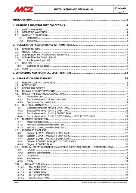
INSTALLATION AND USE MANUAL<br />
<strong>Contents</strong><br />
page 1<br />
INTRODUCTION ....................................................................................................................................3<br />
1. WARNINGS AND WARRANTY CONDITIONS .....................................................................................4<br />
1.1. SAFETY WARNINGS ........................................................................................................................4<br />
1.2. OPERATING WARNINGS..................................................................................................................4<br />
1.3. WARRANTY CONDITIONS................................................................................................................4<br />
1.3.1. Restrictions..............................................................................................................................5<br />
1.3.2. Exclusions................................................................................................................................5<br />
2. INSTALLATION IN ACCORDANCE WITH UNI 10683 .........................................................................6<br />
2.1. OPERATING AREA...........................................................................................................................6<br />
2.2. PRECAUTIONS................................................................................................................................6<br />
2.3. CONNECTION TO THE EXTERNAL AIR INTAKE ..................................................................................7<br />
2.4. CONNECTION TO THE FLUE PIPE.....................................................................................................8<br />
2.4.1. Smoke valve (optional) .............................................................................................................8<br />
2.5. FLUE PIPE......................................................................................................................................8<br />
2.5.1. Examples of flue pipes ..............................................................................................................9<br />
2.6. COWL ..........................................................................................................................................10<br />
3. DIMENSIONS AND TECHNICAL SPECIFICATIONS ..........................................................................12<br />
4. INSTALLATION AND ASSEMBLY......................................................................................................15<br />
4.1. PREPARATION AND UNPACKING....................................................................................................15<br />
4.2. POSITIONING...............................................................................................................................15<br />
4.3. HEIGHT ADJUSTMENT ..................................................................................................................16<br />
4.4. RELEASE OF COUNTERWEIGHTS ...................................................................................................16<br />
4.5. MAKING THE ELECTRICAL CONNECTIONS ......................................................................................17<br />
4.5.1. The control unit .....................................................................................................................17<br />
4.5.2. Electrical connection of the control unit ....................................................................................18<br />
4.5.3. Operation of the control unit ...................................................................................................19<br />
4.6. ELECTRICAL DIAGRAMS ................................................................................................................21<br />
4.6.1. Electrical connection for Kit 1 OPEN TANK ................................................................................21<br />
4.6.2. Electrical connection for Kit 2 OPEN TANK ................................................................................22<br />
4.6.3. Electrical connection for Kit 1 CLOSED TANK ............................................................................23<br />
4.6.4. Electrical connection for Kit 3 OPEN TANK and KIT 2 CLOSED TANK ...........................................24<br />
4.7. PLUMBING CONNECTION ..............................................................................................................25<br />
4.7.1. Water characteristics ..............................................................................................................25<br />
4.7.2. Hydraulic connection with Open Tank ......................................................................................26<br />
4.7.3. Hydraulic connection with Closed Tank.....................................................................................26<br />
4.8. HYDRAULIC DIAGRAMS.................................................................................................................27<br />
4.8.1. Diagram 1 OPEN TANK (KIT 1 OPEN TANK)..............................................................................27<br />
4.8.2. Diagram 2 OPEN TANK (KIT 2 OPEN TANK)..............................................................................28<br />
4.8.3. Diagram 3 OPEN TANK (KIT 3 OPEN TANK)..............................................................................29<br />
4.8.4. Diagram 1 CLOSED TANK (KIT 1 CLOSED TANK) ......................................................................30<br />
4.8.5. Diagram 2 CLOSED TANK........................................................................................................31<br />
4.9. THERMAL SAFETY DISCHARGE VALVE FOR CLOSED TANK CIRCUIT (HYDROTHERM 70V) .................32<br />
4.9.1. Function ................................................................................................................................32<br />
4.9.2. Technical specifications...........................................................................................................32<br />
4.9.3. Installation ............................................................................................................................33<br />
4.9.4. Maintenance ..........................................................................................................................34<br />
4.9.5. Safety ...................................................................................................................................34<br />
4.10. INSTALLATION KIT....................................................................................................................35<br />
4.10.1. Kit 1 OPEN TANK ................................................................................................................35<br />
4.10.2. Kit 2 OPEN TANK ................................................................................................................36<br />
4.10.3. Kit 3 OPEN TANK ................................................................................................................36<br />
4.10.4. Kit 1 CLOSED TANK.............................................................................................................37<br />
4.10.5. Kit 2 CLOSED TANK.............................................................................................................37<br />
<strong>Contents</strong><br />
Technical service – <strong>MCZ</strong> S.p.A. all rights reserved - Reproduction prohibited
INSTALLATION AND USE MANUAL<br />
<strong>Contents</strong><br />
page 2<br />
4.11. UNIT CLADDING.......................................................................................................................38<br />
4.11.1. INSULATION OF FIREPLACE STOVE......................................................................................38<br />
4.11.2. INSULATING A WOODEN BEAM............................................................................................38<br />
4.11.3. Decorative hood..................................................................................................................38<br />
5. OPERATION .....................................................................................................................................39<br />
5.1. PRE-LIGHTING WARNINGS............................................................................................................39<br />
5.2. OPERATING TEST .........................................................................................................................39<br />
5.3. CHOICE OF FUEL ..........................................................................................................................41<br />
5.4. LOADING THE FUEL......................................................................................................................41<br />
5.5. CONTROL OF COMBUSTION ..........................................................................................................42<br />
5.6. FIRST LIGHTING ..........................................................................................................................42<br />
5.7. EMERGENCY SITUATIONS .............................................................................................................43<br />
6. MAINTENANCE AND CLEANING ......................................................................................................44<br />
6.1. CLEANING TO BE PERFORMED BY THE USER..................................................................................44<br />
6.1.1. Cleaning the glass ..................................................................................................................44<br />
6.1.2. Cleaning the exchanger ..........................................................................................................44<br />
6.1.3. Cleaning out the ashes ...........................................................................................................44<br />
6.1.4. Cleaning flue pipe...................................................................................................................45<br />
6.1.5. Lubrication and routine maintenance of the extensible guides ....................................................45<br />
7. DOOR ADDITIONAL WEIGHT KIT....................................................................................................46<br />
7.1. Supplementary weight kits for door closure (only available for closed tank version) ............................46<br />
<strong>Contents</strong><br />
Technical service – <strong>MCZ</strong> S.p.A. all rights reserved - Reproduction prohibited
INSTALLATION AND USE MANUAL<br />
Chapter 1<br />
page 3<br />
INTRODUCTION<br />
Dear customer,<br />
Thank you for choosing an <strong>MCZ</strong> product, specifically a<br />
fireplace stove of the Forma line.<br />
We are sure that, with use, you will appreciate the<br />
quality of an attentively designed and tested product.<br />
Our goal is to combine technology with easy use and,<br />
above all, safety.<br />
For best fireplace stove operations and to fully<br />
enjoy the heat and sense of well being it will<br />
spread throughout your home, we suggest you<br />
carefully read this booklet before use. Please<br />
contact your dealer for full assistance in<br />
resolving any doubts or problems.<br />
Congratulations on your choice and remember, the<br />
fireplace stove MUST NEVER be used by children<br />
who should always be kept at a safe distance!<br />
These symbols signal specific messages<br />
in this booklet<br />
WARNING:<br />
This warning symbol found in various<br />
points in this manual indicates that the<br />
user should carefully read and understand<br />
the message to which it refers since<br />
neglect to follow these instructions<br />
could cause serious fireplace stove<br />
damage or injury to the user.<br />
INFORMATION:<br />
This symbol intends to emphasise<br />
important information for good fireplace<br />
stove operations. Failure to observe these<br />
instructions could jeopardise product use<br />
and operations may be unsatisfactory<br />
Revisions to the publication<br />
In order to improve the product, the Manufacturer<br />
reserves the right to modify and update this<br />
publication without prior notice.<br />
Reproduction, even partial, of this manual without the<br />
Manufacturer's authorisation is prohibited.<br />
Manual preservation<br />
• Please take care of this manual and keep it in a<br />
place that can be quickly and easily reached.<br />
• If this manual should be lost or destroyed, or if it<br />
is in poor condition, ask for a copy from your<br />
retailer or directly from the manufacturer,<br />
providing product identification data.<br />
How to read the manual<br />
• An essential item or one that requires specific<br />
attention is published in “bold”.<br />
• “Italics" are used for any additional clarification.<br />
• NOTE: the “NOTE” provides the reader with<br />
additional information on the subject.<br />
Introduction<br />
Technical service – <strong>MCZ</strong> S.p.A. all rights reserved - Reproduction prohibited
INSTALLATION AND USE MANUAL<br />
Chapter 1<br />
page 4<br />
1. WARNINGS AND WARRANTY<br />
CONDITIONS<br />
1.1. SAFETY WARNINGS<br />
• Installation of the stove, electrical<br />
connections, checking its operation, and<br />
maintenance are all tasks which should be<br />
carried out by qualified and authorised<br />
personnel.<br />
• Install the fireplace stove according to<br />
correct local, regional or state regulations.<br />
• For correct use of the fireplace stove and<br />
accessories, and to prevent accidents, always<br />
follow the instructions in this booklet.<br />
• Before beginning any operation, anyone who<br />
uses the stove must read and understand the<br />
entire contents of this instruction booklet.<br />
• The fireplace stove must be used only for its<br />
intended purpose. Any other use is considered<br />
improper and therefore hazardous.<br />
• Check the conditions of the surface that will<br />
support the weight of the stove. If it is made of<br />
flammable material such as wood, carpet, or<br />
plastic, provide suitable insulation.<br />
• Avoid installation in rooms with B type gas<br />
devices, hoods with or without exhaust, heat<br />
pumps, collective ventilation conduits.<br />
• Do not install several flue pipes in one room, and<br />
avoid having a stairwell in the vicinity. Check that<br />
in adjacent connected room there are not any<br />
units whose simultaneous use would create<br />
negative pressure in one of the two rooms.<br />
• The user is fully liable for improper product use,<br />
releasing <strong>MCZ</strong> from any civil or penal liabilities.<br />
• Any tampering with the fireplace stove, or use of<br />
non-original spare parts, may be hazardous to<br />
the user and releases <strong>MCZ</strong> from any civil or penal<br />
liability.<br />
• Parts of the surfaces of the fireplace stove are<br />
very hot (door, handle, glass). Therefore, avoid<br />
direct contact with these parts unless wearing<br />
protective clothing or specific means such as, for<br />
example, heat protective gloves or "cold"<br />
activation devices.<br />
• Carefully explain this hazard to elderly people,<br />
disabled people and particularly to all children,<br />
keeping them away from the fireplace stove<br />
while it is in operation.<br />
• Incorrect installation or poor maintenance (not<br />
compliant with the provisions of this manual)<br />
may cause damages to persons, animals or<br />
property. <strong>MCZ</strong> is not civilly or criminally liable in<br />
Warnings and warranty conditions<br />
these cases.<br />
1.2. OPERATING WARNINGS<br />
• Turn off the fireplaces stove in the event of faults<br />
or poor operations.<br />
• Never place flammable materials closer than 150<br />
cm to the fireplace stove.<br />
• If the chimney flue draught is poor (due to bad<br />
weather or improper installation), start the fire<br />
decisively while keeping the door slightly ajar.<br />
When you close the door, keep the air register<br />
completely open. Use small pieces of dry wood.<br />
If combustion problems continue, please contact<br />
a specialized technician.<br />
• Install the fireplace stove in a location which is<br />
suitable for fire fighting, and equipped with all<br />
services such as air, water and electricity supply<br />
and smoke discharge.<br />
• Do not light the fire with flammable materials.<br />
• To clean the appliance's chimney, remove the<br />
smoke deflector. To remove it correctly, lift the<br />
front and at the same time slide it forward in<br />
order to free it from rear support.<br />
INFORMATION:<br />
• For any problem, please contact your dealer or<br />
<strong>MCZ</strong> qualified and authorised personnel and<br />
always request original spare parts for repairs.<br />
• Only use the fuel stated by <strong>MCZ</strong>.<br />
• Check and periodically clean the smoke exhaust<br />
stack as foreseen by current regulations in the<br />
country of installation.<br />
• If there is a fire in the flue pipe, keep the door of<br />
the fireplace stove and the combustion air<br />
register closed at all times. Request assistance<br />
from the competent authorities.<br />
• Carefully conserve the instruction booklet. It<br />
must remain with the fireplace stove for its entire<br />
life cycle. If the stove is sold or transferred to<br />
another user, make sure the manual<br />
accompanies the product.<br />
• If lost, please request a copy from your dealer or<br />
from <strong>MCZ</strong>.<br />
1.3. WARRANTY CONDITIONS<br />
<strong>MCZ</strong> guarantees the product, except for the<br />
elements subject to normal wear listed below, for<br />
two years from the date of purchase proven by a<br />
document that indicates the dealer's name and date<br />
of sale, if the completed warranty certificate was<br />
returned within 8 days and if the product was<br />
installed and inspected by a specialised installation<br />
Technical service – <strong>MCZ</strong> S.p.A. all rights reserved - Reproduction prohibited
INSTALLATION AND USE MANUAL<br />
Chapter 1<br />
page 5<br />
technician and according to the detailed instructions<br />
indicated in the instruction manual supplied with the<br />
product.<br />
The warranty includes the free replacement or repair<br />
of parts recognised as factory defective.<br />
authorisation.<br />
Only original <strong>MCZ</strong> spare parts must be<br />
used for all replacements.<br />
1.3.1. Restrictions<br />
The above guarantee does not cover components<br />
relating to electrical parts, on which the guarantee<br />
period is 1 year from the purchase of the product,<br />
documented as specified above. The warranty does<br />
not cover parts subject to normal wear such as:<br />
gaskets, glass, and all removable fire box parts.<br />
Replaced parts will be guaranteed for the remaining<br />
warranty period from the date of product purchase.<br />
Specifically, glass is guaranteed from<br />
the moment the <strong>MCZ</strong> installation<br />
technician certifies its integrity when<br />
installation is completed.<br />
1.3.2. Exclusions<br />
The warranty does not cover any part that may<br />
be defective due to negligence or careless use,<br />
incorrect maintenance, installation non<br />
compliant with that specified by <strong>MCZ</strong> (see<br />
relevant chapters in this manual).<br />
<strong>MCZ</strong> refuses to accept any responsibility for any<br />
damage which may be caused, directly or indirectly,<br />
by persons, animals or things as a result of the failure<br />
to observe all the provisions set forth in the<br />
instruction booklet, especially those concerning<br />
warnings on the subject of installation, use and<br />
maintenance of the appliance.<br />
In the event of product inefficiency, please contact<br />
your dealer and/or area importer.<br />
Damages caused by transport and handling are not<br />
covered by the warranty.<br />
Exclusively refer to the supplied manual for product<br />
installation and use.<br />
The warranty is null and void in the event of damage<br />
due to tampering, weather, natural calamities,<br />
lightening, fire, defective electrical and hydraulic<br />
systems and the lack or incorrect maintenance as per<br />
the manufacturer's instructions.<br />
SERVICE REQUESTS<br />
Service requests must be addressed<br />
to the dealer who shall forward the<br />
request to <strong>MCZ</strong> technical assistance.<br />
<strong>MCZ</strong> is not liable in the event the<br />
product and any other accessory is<br />
improperly used or modified without<br />
Warnings and warranty conditions<br />
Technical service – <strong>MCZ</strong> S.p.A. all rights reserved - Reproduction prohibited
INSTALLATION AND USE MANUAL<br />
Chapter 2<br />
page 6<br />
2. INSTALLATION IN ACCORDANCE WITH UNI<br />
10683<br />
2.1. OPERATING AREA<br />
For good operations and good heat distribution, the fireplace stove<br />
should be positioned in a place where the air required for combustion<br />
can flow (at least 60 m 3 /h must be available) according to installation<br />
standards and current regulations in the country of installation.<br />
The room volume must not be less than 60 m 3 .<br />
Air must enter through permanent apertures on the walls (near the<br />
fireplace stove) that open outdoors with a minimum section of 360 cm 2 .<br />
These apertures (air vents) must be made so as not to be obstructed in<br />
any way.<br />
Air can also be taken from adjacent rooms as long as these are<br />
equipped with outdoor air vents and not bedrooms or bathrooms or<br />
rooms where fire hazards do not exist such as garages, wood sheds,<br />
flammable material warehouses, strictly observing the provisions of<br />
current regulations.<br />
• Fireplace stoves may not be installed in<br />
bedrooms, bathrooms and where another<br />
heating device is installed without autonomous<br />
air flow (fireplace, stove, etc.).<br />
• Placing the fireplace stove in explosive<br />
environments is prohibited.<br />
• The floor of the room where the fireplace stove<br />
is to be installed must be strong enough to<br />
support its weight.<br />
• In the event of wood floors, install a protective<br />
covering in accordance with current regulations<br />
in the country of installation.<br />
• If walls are not flammable, install the fireplace<br />
stove at least 5 cm from the walls.<br />
2.2. PRECAUTIONS<br />
The fireplace stove must be installed in a suitable surface that permits<br />
routine opening and maintenance operations.<br />
The room must be:<br />
• suitable for room operating conditions<br />
• equipped with power supply 230V 50 Hz (EN73-23)<br />
• equipped with an adequate smoke exhaust system<br />
• equipped with outdoor ventilation<br />
• provided with an earth connection complying with CEI 64-8<br />
Theoretical notions for installation<br />
Technical service – <strong>MCZ</strong> S.p.A. all rights reserved - Reproduction prohibited
INSTALLATION AND USE MANUAL<br />
Chapter 2<br />
page 7<br />
IMPORTANT!<br />
• The fireplace stove must be installed and<br />
assembled by qualified personnel.<br />
• The fireplace stove must be connected to a flue<br />
pipe or other vertical smoke stack that can<br />
discharge smoke at the highest point of the<br />
house.<br />
• The fireplace stove must be connected to a flue<br />
pipe or an internal or external vertical duct<br />
conforming to current standards UNI 7129 -<br />
7131 9615.<br />
• Smoke is generated from burning wood and,<br />
therefore, may dirty adjacent or nearby walls.<br />
• Before positioning the fireplace stove, you must<br />
make a hole for the intake of external air.<br />
2.3. CONNECTION TO THE EXTERNAL AIR INTAKE<br />
The room where the stove is installed must have at least as much air as<br />
requested by normal combustion of the equipment and by room<br />
ventilation. This may take place through permanent apertures in the<br />
room walls that lead directly outdoors or ventilated rooms according to<br />
UNI 10683.<br />
For this purpose, drill a hole with minimum 360 cm² free section near<br />
the fireplace stove (22 cm diameter or a 20x18cm rectangle), protected<br />
by an indoor and outdoor grille.<br />
The air intake must also:<br />
• directly communicate with the installation room<br />
• be protected by a grill, made of metallic anti-insect mesh or a<br />
suitable protection as long as it does not reduce the minimum<br />
section.<br />
• be installed so as to avoid obstruction<br />
• for ducts, up to 3.5 linear metres, increase the section by about<br />
5% while increased by 15% for larger measurements.<br />
Remember that the ventilation grills always have a cm 2<br />
useful section on one side. When selecting the grill and hole<br />
dimension, make sure the useful grill section is greater than<br />
or equal to the section required by <strong>MCZ</strong> for product<br />
operations.<br />
Connecting the air outlet directly to the fireplace stove is not<br />
mandatory but the above mentioned section must guarantee<br />
about 50 m³/h of air. See standard UNI 10683.<br />
IMPORTANT!<br />
Air flow may also be obtained from a room adjacent<br />
to the installation room as long as this flow is free<br />
through permanent apertures that directly<br />
communicate with the outdoors; avoid air outlets<br />
connecting with heating units, garages, kitchens or<br />
bathrooms.<br />
Theoretical notions for installation<br />
Technical service – <strong>MCZ</strong> S.p.A. all rights reserved - Reproduction prohibited
INSTALLATION AND USE MANUAL<br />
Chapter 2<br />
page 8<br />
2.4. CONNECTION TO THE FLUE PIPE<br />
The connection to the flue pipe is a very important element. The<br />
connection must be made with a great deal of care; in the event of<br />
erroneous or anomalous construction, it is extremely difficult to remedy<br />
without damaging the hood liner. In addition, the connection is made in<br />
a part of the stove where temperatures are very high, and for this<br />
reason it is important to use materials that are capable of resisting heat<br />
and also the acidity of the fumes produced by combustion.<br />
Before beginning work, please note the following:<br />
• The connecting pipe must have a maximum slope of 45<br />
degrees. This is to avoid excessive deposit of condensation<br />
produced in the initial phases of lighting the fireplace stove,<br />
and/or the excessive accumulation of creosote. It also keeps<br />
the release of smoke from being slowed down.<br />
• The connections must be made of stainless steel 316<br />
with a minimum thickness of 10/10, or in aluminised<br />
steel, minimum thickness 20/10. It is prohibited to use<br />
stainless steel or aluminium hoses as they compromise<br />
the safety of the connection and are subject to tears<br />
and gaps, causing leakage of smoke.<br />
• The components making up the connecting pipe must be<br />
perfectly sealed.<br />
• The joint to the flue pipe must not be too long (to avoid<br />
obstructions), nor too short (to avoid smoke leakage).<br />
A<br />
Smoke<br />
connection<br />
Ceramic fibre<br />
insulation<br />
Hood grille<br />
Flue pipe<br />
45° max<br />
If metal connecting pipes are used, they must be<br />
insulated with suitable material such as ceramic fibre<br />
matting, to avoid deterioration of the masonry and of<br />
the decorative hood liner.<br />
IMPORTANT!<br />
Any increase in the section of the connecting pipe<br />
must start immediately above the hood of the<br />
fireplace and not along the flue pipe section.<br />
2.4.1. Smoke valve (optional)<br />
In case of excessive draught in the flue chimney, combustion may<br />
become unbalanced and consequently less efficient. In this case, in<br />
order to improve combustion efficiency, it is advisable to install the<br />
smoke valve (optional) directly at the output of the fireplace stove. If<br />
you wish to position the control knob (B in the figure) at the front of<br />
the product, it is necessary to place a 25 cm extension of the smoke<br />
duct between the fireplace stove and the valve.<br />
Example of fireplace stove connection in<br />
flue chimney<br />
Illustration of a correctly constructed<br />
chimney flue with a chamber and sealed<br />
door (A) for solid combustion product<br />
collection and discharge at the foot of the<br />
external ascending segment.<br />
30°<br />
2.5. FLUE PIPE<br />
The flue pipe is a fundamental element in discharging smoke and<br />
therefore must have the following requisites:<br />
• It must be waterproof and thermally insulated.<br />
• It must be made with heat resistant materials, resistant to<br />
combustion products and any condensation.<br />
• It must have a vertical slope with axis deviations not over 45°<br />
and without narrowing.<br />
Smoke valve<br />
B<br />
Theoretical notions for installation<br />
Technical service – <strong>MCZ</strong> S.p.A. all rights reserved - Reproduction prohibited
INSTALLATION AND USE MANUAL<br />
Chapter 2<br />
page 9<br />
• It must meet the requisites indicated in the technical table for<br />
the internal chimney section and height.<br />
• It must preferably have a circular interior section.<br />
• If pre-existing and previously used, it must be cleaned.<br />
The flue pipe is of primary importance for the correct<br />
functioning and safety of your fireplace stove.<br />
2.5.1. Examples of flue pipes<br />
AISI 304 stainless steel flue<br />
pipe with dual chamber<br />
insulated with ceramic wool<br />
or equivalent resistant to<br />
400°C.<br />
EXCELLENT<br />
Flue pipe in refractory brick<br />
with insulated double wall and<br />
external coat of cement mix<br />
lightened with honeycomb<br />
material such as clay.<br />
GOOD<br />
Traditional square section<br />
clay flue pipe with insulating<br />
hollow inserts.<br />
GOOD<br />
Avoid flue pipes with internal<br />
rectangular sections whose<br />
larger side is double the smaller<br />
such as 20x40 or 15x30.<br />
AVERAGE<br />
Square or rectangular section flue pipes must have rounded internal<br />
corners with radius not less than 20mm. For the rectangular section,<br />
the ratio between internal dimensions must be ≤1.5.<br />
The recommended section for a flue pipe according to its length is<br />
listed in the table below:<br />
Altezza (m) Sezione (cm²) Fireplace stove<br />
Fino a 5 mt 30x30 cm Ø30 HYDROTHERM 80<br />
Oltre 5 mt 25x25 cm Ø25 HYDROTHERM 80<br />
Fino a 5 mt 25x25 cm Ø25 HYDROTHERM 70<br />
Oltre 5 mt 20x20 cm Ø20 HYDROTHERM 70<br />
N.B. Too small or too large a section reduces draught and insulation.<br />
For special sections, or section or path variations, functional smoke<br />
exhaust inspections must be conducted as per UNI 9615.<br />
The smoke duct should be equipped with a solid material collection<br />
chamber at the mouth of the smoke duct to be easily opened with an<br />
airtight door.<br />
Theoretical notions for installation<br />
Technical service – <strong>MCZ</strong> S.p.A. all rights reserved - Reproduction prohibited
INSTALLATION AND USE MANUAL<br />
Chapter 2<br />
page 10<br />
IMPORTANT !<br />
In the event of doubt on your chimney flue<br />
operations or that its dimensions are different from<br />
those recommended, we highly suggest an<br />
authorised <strong>MCZ</strong> technician inspect and measure<br />
chimney flue performance (micro-gauge<br />
measurements)<br />
<strong>MCZ</strong> s.p.a. shall not be held liable for poor operation<br />
of the fireplace stove that is due to a flue pipe of<br />
improper size or installation that does not comply<br />
with provided requirements.<br />
2.6. COWL<br />
If underestimated, it is a severe impediment to correct "chimney<br />
system" operations.<br />
Flue pipe draught also depends on its cowl.<br />
Therefore, if hand made, its four exhaust sections must correspond to<br />
more than twice the internal section of the flue pipe.<br />
Having to exceed the peak of the roof, the cowl will be<br />
exposed to wind, therefore an industrial type is recommended.<br />
An industrial cowl,<br />
with prefabricated<br />
sections fitting<br />
together, allows<br />
optimal disposal of<br />
the flue gases.<br />
A traditional<br />
handmade cowl.<br />
The right exhaust<br />
section must be at<br />
least twice the<br />
internal section of<br />
the flue pipe, 2.5<br />
times is ideal.<br />
Steel cowl for flue pipe<br />
with internal smoke<br />
deflector cone.<br />
Theoretical notions for installation<br />
Technical service – <strong>MCZ</strong> S.p.A. all rights reserved - Reproduction prohibited
INSTALLATION AND USE MANUAL<br />
Chapter 2<br />
page 11<br />
The cowl must meet the following requisites:<br />
• It must have an internal section equal to that of the chimney.<br />
• It must have a useful output section not less that double that<br />
of the internal section of the flue pipe.<br />
• It must be built to prevent rain, snow and any foreign objects<br />
from getting into the flue pipe.<br />
• They must be installed to guarantee adequate smoke<br />
dispersion and out of the reflux area where negative pressure<br />
forms.<br />
1 mt 0,5 mt<br />
For paired flue pipes, the cowl for solid combustion<br />
and the one for the upper floor must be at least 50cm<br />
higher than the other to avoid pressure transfers<br />
between paired flues.<br />
The cowl must not have obstacles within 10 m such as<br />
walls, roof slopes and trees. Otherwise, raise it at least<br />
1 m over the obstacle and, in the event of other<br />
nearby cowls, keep them at least 2 m away. In any<br />
case, the cowl must exceed the peak of the roof by at<br />
least 1m.<br />
Theoretical notions for installation<br />
Technical service – <strong>MCZ</strong> S.p.A. all rights reserved - Reproduction prohibited
INSTALLATION AND USE MANUAL<br />
Chapter 3<br />
page 12<br />
3. DIMENSIONS AND TECHNICAL SPECIFICATIONS<br />
HYDRO THERM 80<br />
Technical specifications<br />
Fuel type<br />
Wood<br />
Hourly consumption<br />
7,1 kg/h<br />
Nominal thermal power kW 26,2 - Kcal 22.532<br />
H 2 O thermal power kW 15,2 - Kcal 13.072<br />
Efficiency 77,1%<br />
Heatable volume * 563/40-644/35-751/30<br />
Minimum draught<br />
12 Pa / 0,12 mbar<br />
Smoke temperature 333 °C<br />
Smoke outlet<br />
Ø 25 cm<br />
Net weight<br />
232 Kg<br />
External combustion air outlet cm² 200<br />
CO emission in smoke (13 %O 2 ) 0,61%<br />
Massive smoke capacity<br />
17,7 g/s<br />
Permissible max. water pressure<br />
1,5 bar<br />
Flue pipe<br />
Up to 5 m<br />
30x30 cm Ø30<br />
Over 5 m<br />
25x25 cm Ø25<br />
Note<br />
Intermittent combustion unit<br />
* Data may vary according to the fuel used<br />
HYDRO THERM 80E<br />
Technical specifications<br />
Fuel type<br />
Wood<br />
Hourly consumption<br />
7,1 kg/h<br />
Nominal thermal power kW 26,2 - Kcal 22.532<br />
H 2 O thermal power kW 15,2 - Kcal 13.072<br />
Efficiency 77,1%<br />
Heatable volume * 563/40-644/35-751/30<br />
Minimum draught<br />
12 Pa / 0,12 mbar<br />
Smoke temperature 333 °C<br />
Smoke outlet<br />
Ø 25 cm<br />
Net weight<br />
235 Kg<br />
External combustion air outlet cm² 200<br />
CO emission in smoke (13 %O 2 ) 0,61%<br />
Massive smoke capacity<br />
17,7 g/s<br />
Permissible max. water pressure<br />
1,5 bar<br />
Flue pipe<br />
Up to 5 m<br />
30x30 cm Ø30<br />
Over 5 m<br />
25x25 cm Ø25<br />
Note<br />
Intermittent combustion unit<br />
* Data may vary according to the fuel used<br />
Dimensions and technical specifications<br />
Technical service – <strong>MCZ</strong> S.p.A. all rights reserved - Reproduction prohibited
INSTALLATION AND USE MANUAL<br />
Chapter 3<br />
page 13<br />
HYDRO THERM 70<br />
Technical specifications<br />
Fuel type<br />
Hourly consumption<br />
Wood<br />
6,5 kg/h<br />
Nominal thermal power Kw 21,2 - Kcal 18.232<br />
H 2 O thermal power kW 13,0 - Kcal 11.180<br />
Efficiency 75,2 %<br />
Heatable volume * 456/40-521/35-608/30<br />
Minimum draught<br />
12 Pa / 0,12 mbar<br />
Smoke temperature 310 °C<br />
Smoke outlet<br />
Net weight<br />
Ø 20 cm<br />
195 Kg<br />
External combustion air outlet cm² 200<br />
CO emission in smoke (13<br />
%O 2 )<br />
Massive smoke capacity<br />
Permissible max. water<br />
pressure<br />
Flue pipe<br />
Up to 5 m<br />
Over 5 m<br />
0,87%<br />
14,4 g/s<br />
1,5 bar<br />
25x25 cm Ø25<br />
20x20 cm Ø20<br />
Note<br />
Intermittent combustion unit<br />
* Data may vary according to the fuel used<br />
HYDRO THERM 70V<br />
Technical specifications<br />
Fuel type<br />
Hourly consumption<br />
Wood<br />
6,5 kg/h<br />
Nominal thermal power kW 21,2 - Kcal 18.232<br />
H 2 O thermal power kW 13,0 - Kcal 11.180<br />
Efficiency 75,2 %<br />
Heatable volume * 456/40-521/35-608/30<br />
Minimum draught<br />
12 Pa / 0,12 mbar<br />
Smoke temperature 310 °C<br />
Smoke outlet<br />
Net weight<br />
Ø 20 cm<br />
212 Kg<br />
External combustion air outlet cm² 200<br />
CO emission in smoke (13<br />
%O 2 )<br />
Massive smoke capacity<br />
Permissible max. water<br />
pressure<br />
Flue pipe<br />
Up to 5 m<br />
Over 5 m<br />
0,87%<br />
14,4 g/s<br />
2,0 bar<br />
25x25 cm Ø25<br />
20x20 cm Ø20<br />
Note<br />
Intermittent combustion unit<br />
* Data may vary according to the fuel used<br />
Dimensions and technical specifications<br />
Technical service – <strong>MCZ</strong> S.p.A. all rights reserved - Reproduction prohibited
INSTALLATION AND USE MANUAL<br />
Chapter 3<br />
page 14<br />
HYDRO THERM 70SX<br />
OUTLET<br />
G 1"<br />
INLET G 1"<br />
Technical specifications<br />
Fuel type<br />
Hourly consumption<br />
Wood<br />
6,5 kg/h<br />
Nominal thermal power kW 21,2 - Kcal 18.232<br />
H 2 O thermal power kW 13,0 - Kcal 11.180<br />
Efficiency 75,2 %<br />
Heatable volume * 456/40-521/35-608/30<br />
Minimum draught<br />
12 Pa / 0,12 mbar<br />
Smoke temperature 310 °C<br />
Smoke outlet<br />
Net weight<br />
Ø 20 cm<br />
204 Kg<br />
External combustion air outlet cm² 200<br />
CO emission in smoke (13<br />
%O 2 )<br />
Massive smoke capacity<br />
Permissible max. water<br />
pressure<br />
Flue pipe<br />
Up to 5 m<br />
Over 5 m<br />
0,87%<br />
14,4 g/s<br />
1,5 bar<br />
25x25 cm Ø25<br />
20x20 cm Ø20<br />
Note<br />
Intermittent combustion unit<br />
* Data may vary according to the fuel used<br />
HYDRO THERM 70DX<br />
INLET G 1"<br />
OUTLET<br />
G 1"<br />
Technical specifications<br />
Fuel type<br />
Hourly consumption<br />
Wood<br />
6,5 kg/h<br />
Nominal thermal power kW 21,2 - Kcal 18.232<br />
H 2 O thermal power kW 13,0 - Kcal 11.180<br />
Efficiency 75,2 %<br />
Heatable volume * 456/40-521/35-608/30<br />
Minimum draught<br />
12 Pa / 0,12 mbar<br />
Smoke temperature 310 °C<br />
Smoke outlet<br />
Net weight<br />
Ø 20 cm<br />
204 Kg<br />
External combustion air outlet cm² 200<br />
CO emission in smoke (13<br />
%O 2 )<br />
Massive smoke capacity<br />
Permissible max. water<br />
pressure<br />
Flue pipe<br />
Up to 5 m<br />
Over 5 m<br />
0,87%<br />
14,4 g/s<br />
1,5 bar<br />
25x25 cm Ø25<br />
20x20 cm Ø20<br />
Note<br />
Intermittent combustion unit<br />
* Data may vary according to the fuel used<br />
Dimensions and technical specifications<br />
Technical service – <strong>MCZ</strong> S.p.A. all rights reserved - Reproduction prohibited
INSTALLATION AND USE MANUAL<br />
Chapter 4<br />
page 15<br />
4. INSTALLATION AND ASSEMBLY<br />
IMPORTANT!<br />
The fireplace stove must be installed and connected<br />
to the smoke duct only by a specialized technician, so<br />
that all local and national regulations are complied<br />
with.<br />
Installation must in any case by carried out in<br />
compliance with UNI 10683.<br />
When the fireplace is unpacked, check for perfect operation of all<br />
its parts or any damage which may have occurred during<br />
shipping. The retailer or the carrier must be immediately<br />
informed of any damage.<br />
If the fireplace stove is installed in a place that is difficult to reach, its<br />
weight can be reduced by removing the internal parts that make up the<br />
fire box. However, be sure to put all of the parts back in place.<br />
This operation is to be carried out only by specialized<br />
personnel.<br />
<strong>MCZ</strong> shall not be held liable if the preceding warning is not<br />
complied with.<br />
4.1. PREPARATION AND UNPACKING<br />
Open the packaging, remove the stove unit from the pallet and position<br />
it in the chosen location, taking care that its position complies with the<br />
above instructions.<br />
The fireplace stove must always be kept VERTICAL<br />
while moving and only using hand trucks. Do not<br />
drag the unit as this may damage the support feet.<br />
Be especially careful that the door and its glass are protected from<br />
mechanical collisions that could jeopardise their integrity.<br />
Moving the product must be done with care. If possible, unpack the<br />
fireplace stove in the area where it is to be installed.<br />
The materials which make up the packaging are not toxic or harmful,<br />
so no special procedures for disposal are required.<br />
The final user must store, dispose or recycle packaging material in<br />
accordance with local regulations.<br />
4.2. POSITIONING<br />
The HYDROTHERM fireplace stove can be placed in a corner or along a<br />
wall. You can customize with <strong>MCZ</strong> claddings or install them during<br />
construction with materials that are resistant to high temperatures.<br />
The fireplace stoves are self-supporting single-piece units that simplify<br />
installation and do not require any additional support.<br />
Always evaluate the structural condition of the surface which<br />
will take the weight, and always leave a minimum 5 cm<br />
airspace between the stove and any walls.<br />
Install dry the fire bed of the cladding leaving an opening of 1 cm<br />
for the insulation.<br />
1 cm<br />
5 cm<br />
Installation and assembly<br />
Technical service – <strong>MCZ</strong> S.p.A. all rights reserved - Reproduction prohibited
INSTALLATION AND USE MANUAL<br />
Chapter 4<br />
page 16<br />
For installation near flammable material, comply with the following<br />
minimum safe distances:<br />
• Distance from the sides and back= 100 mm<br />
• Height above floor = 80 mm<br />
• Insulating material on sides and back= 80 mm<br />
• Insulating material on the floor = 25 mm<br />
If the stove is positioned over a floor or close to<br />
walls made of flammable materials, it is advisable to<br />
use sufficient insulation.<br />
25 80<br />
The hot air outlets must be placed at least 300 mm<br />
from other materials (e.g. curtains)<br />
100<br />
4.3. HEIGHT ADJUSTMENT<br />
The Hydrotherm fireplace stove is equipped with adjustment feet,<br />
whose purpose is to allow the easy levelling of the fire bed. The feet<br />
allow an adjustment of about 6-7 cm and are mounted on the pre-set<br />
brackets (See figure)<br />
If you want to raise the fireplace stove by more than 6-7 cm, you need<br />
to create a masonry pedestal to set the product on. Do not eliminate<br />
the feet. They are indispensable for levelling.<br />
If the fireplace stove is not placed level, there is the<br />
risk that door will not close perfectly, and that the<br />
internal counterweights strike the structure, causing<br />
noise each time the door is raised or lowered.<br />
It is possible to adjust the levelling of the fireplace<br />
stove by checking the sliding of the door until it no<br />
longer makes any noise.<br />
100 80<br />
100<br />
80<br />
4.4. RELEASE OF COUNTERWEIGHTS<br />
The fireplace stove is delivered with the sliding counterweights locked<br />
in place. In this way, during shipping and handling, they will not strike<br />
and damage the sliding parts, the door and the ceramic glass.<br />
To release the counterweights and therefore also the door, remove the<br />
screws as shown in figure 2 from both sides of the fireplace stove.<br />
Remove the screws that hold the counterweights<br />
only after you have positioned the fireplace stove<br />
and to ensure that the glass is in good condition.<br />
DO NOT MOVE THE FIREPLACE STOVE WITHOUT THE<br />
SCREWS THAT HOLD THE COUNTERWEIGHTS.<br />
Damage caused by failure to observe this rule is the<br />
responsibility of the client or his representative.<br />
Installation and assembly<br />
Technical service – <strong>MCZ</strong> S.p.A. all rights reserved - Reproduction prohibited
INSTALLATION AND USE MANUAL<br />
Chapter 4<br />
page 17<br />
4.5. MAKING THE ELECTRICAL CONNECTIONS<br />
<strong>MCZ</strong> shall not be held liable for any damage to<br />
persons or objects due to incorrect connections or<br />
improper use of the device.<br />
The Hydrotherm fireplace stove is managed by a control unit (C) fitted with:<br />
• Recessed box (S).<br />
• Temperature probe (T).<br />
• Cover plate (P).<br />
• Control unit body (C)<br />
• Instruction sheet (K).<br />
K<br />
The control panel must be installed far from heat<br />
sources and in a way that the length of the cables<br />
provided is sufficient.<br />
The box must not be installed on the hood of the<br />
cladding.<br />
The cables must not remain in contact with the metal<br />
structure.<br />
When installing the control panel, a 230Vac-50Hz power supply cable<br />
must be provided.<br />
4.5.1. The control unit<br />
The thermal adjuster has the task of:<br />
• Detecting, measuring and displaying the temperature of the<br />
boiler.<br />
• Control the control devices in the system.<br />
• Signal when the boiler exceeds the safety temperature through<br />
an acoustic and luminous signal.<br />
TECHNICAL CHARACTERISTICS<br />
Power supply:<br />
Power<br />
consumption:<br />
Temperature<br />
probe:<br />
Outputs:<br />
Dimensions:<br />
230 Vac ±10%~ 50 Hz; Protection fuse T3,15 A<br />
2VA~<br />
In silicone/pvc cable<br />
Operating temperature: -50°C / 130 °C<br />
Measure limits: 0 – 99 °C Precision: ± 1°C<br />
PUMP output:<br />
powered at 230 Vac - max flow 5A - 250 Vac<br />
VALV output:<br />
free contact - max flow 5A - 250 Vac<br />
AUX output:<br />
free contact - max flow 5A - 250 Vac<br />
Recessed thermal adjuster: 120 x 80 x 50 [mm]<br />
P Cover plate<br />
C Control unit<br />
S Recessed box<br />
Temperature<br />
T<br />
probe<br />
I Inputs<br />
U Outputs<br />
F Fuse<br />
P1 MENU button<br />
P2 Increase button<br />
P3 Increase button<br />
P4 ON/OFF button<br />
1 Pump LED 1<br />
2 3-way valve LED<br />
3 Pump LED 2<br />
4 Auxiliary LED<br />
5 ON/OFF LED<br />
6 Display<br />
Installation and assembly<br />
Technical service – <strong>MCZ</strong> S.p.A. all rights reserved - Reproduction prohibited
INSTALLATION AND USE MANUAL<br />
Chapter 4<br />
page 18<br />
4.5.2. Electrical connection of the control unit<br />
The thermal adjuster is made up of:<br />
• Recessed control unit.<br />
• Fruit box.<br />
• Thermal probe and well (included in the supply)<br />
For correct operation and to avoid any damage to electrical/electronic<br />
parts:<br />
• Place the device in a dry place far from direct heat sources.<br />
• Place the PROBE by using the specific manifold (optional) in a<br />
way to read the correct temperature of the boiler, avoiding<br />
direct or indirect contact with the flame.<br />
• Place the container-box without the control unit body.<br />
The installation and the electrical connections must<br />
be made by a qualified electrician using adequate<br />
equipment.<br />
Connection to the power supply network must be<br />
made only after connecting the wires in the terminal<br />
board.<br />
LINE<br />
Connect the 230 Vac ±10% -~50 Hz electric line to the terminal boards<br />
[1] and [2] to power the control unit. Protection fuse T3.15 A<br />
INPUTS (I)<br />
Probe: Connection to the probe of the fireplace stove that detects the<br />
system temperature.<br />
Temperature range 0 – 100 °C<br />
Flux: ON/OFF permission for the connection of a flow switch or<br />
thermostat of a boiler for domestic hot water<br />
OUTPUTS (U)<br />
Pump: Connection of the water circulation pump in the heating<br />
system. Terminals [3] and [4]<br />
Valv: Connection of a possible 2/3 wire solenoid valve serving as<br />
domestic valve. Terminals [5] [6] and [7]<br />
Aux: Auxiliary connection to connect a gas boiler to control the<br />
shutdown. Terminals [8] [9] and [10]<br />
P2: Connection to the domestic hot water circulation pump.<br />
Terminals [11] and [12]<br />
Installation and assembly<br />
Technical service – <strong>MCZ</strong> S.p.A. all rights reserved - Reproduction prohibited
INSTALLATION AND USE MANUAL<br />
Chapter 4<br />
page 19<br />
4.5.3. Operation of the control unit<br />
ON/OFF:<br />
The control unit is turned on/off by pressing the P4 button for a<br />
prolonged time (ON/OFF)<br />
The OFF status is signalled by the lighting of the OFF LED<br />
MAIN MENU:<br />
Setting the THERMOSTATS for the operation of the controlled<br />
outputs:<br />
1. PUMP thermostat: to control the operation of the system pump<br />
2. VALV thermostat: to directly control the solenoid valve or<br />
another application<br />
3. AUX thermostat: to integrate the gas boiler, solenoid valve<br />
control or another application<br />
How to change them:<br />
• By simply clicking the P1 (MENU) button, the values of the set<br />
Thermostat scroll, as signalled by the flashing of the associated<br />
PUMP / VALV / AUX LED<br />
• To make a change move to the value of the Thermostat to be<br />
changed<br />
• Change the value using the buttons P3(+) and P2(-)<br />
• To save the change wait about 5 seconds or scroll the values<br />
with the button P1(MENU)<br />
Main menu<br />
parameters:<br />
Min.<br />
Default<br />
values<br />
Max<br />
PUMP thermostat 20 40 85<br />
VALV thermostat 20 40 85<br />
AUX thermostat 20 40 85<br />
ALARM FUNCTION:<br />
If the temperature read by the PROBE exceeds the value of the Alarm<br />
Thermostat A01:<br />
• an acoustic and visual signal is triggered<br />
• SILENCE function: the acoustic signal may be deactivated for 5<br />
minutes by pressing any button.<br />
• After this time, if the alarm condition persists, the acoustic signal<br />
is triggered again.<br />
If the PROBE does not work and/or the Lo alarm appears:<br />
• an out of range downwards is signalled (Temperature below<br />
0°C): Probe interrupted<br />
If the PROBE does not work and/or the Hi alarm appears:<br />
• Hi: indicates an out of range upwards (Temperature above<br />
100°C): Probe in short circuit<br />
Installation and assembly<br />
Technical service – <strong>MCZ</strong> S.p.A. all rights reserved - Reproduction prohibited
INSTALLATION AND USE MANUAL<br />
Chapter 4<br />
page 20<br />
In this case it is advisable to immediately reduce the<br />
combustion and eliminate the causes for the excessive<br />
heating.<br />
It is always advisable to use the hourly quantity of<br />
wood set by <strong>MCZ</strong> to keep the temperature constant<br />
and obtain the performance ensured (page 12)<br />
ANTI-FREEZE FUNCTION:<br />
If the temperature read by the probe goes below the set value of the<br />
anti-freeze thermostat A03:<br />
• The PUMP output is activated<br />
• The display shows ICE<br />
STANDBY FUNCTION:<br />
If the device is OFF<br />
in condition of ALARM or ANTI-FREEZE<br />
• the device automatically switches to ON<br />
PUMP ANTI-SEIZURE FUNCTION:<br />
In case of inactivity of the pump for more than the anti-seizure timer<br />
T01 (about a week)<br />
• the PUMP output is activated for T02 seconds<br />
• The display shows bLP<br />
This function is active also in STANDBY.<br />
PUMP TEST FUNCTION:<br />
By pressing the P3(+) button for a prolonged time<br />
• The PUMP output is activated while pressing the button<br />
• The display shows tSt<br />
SANITARY FUNCTION:<br />
This function aims to manage any system for the production of<br />
domestic hot water (flow switch, 3-way valve, etc..) completely from<br />
the control unit. If the complete <strong>MCZ</strong> domestic hot water kit is<br />
purchased, this function is not necessary since the various elements are<br />
managed by the electronic board of the kit, suitably cabled.<br />
For those who wish to use this function, instructions for the<br />
connections can be found inside the packaging of the control unit.<br />
<strong>MCZ</strong> shall not be held liable for any damage to the<br />
product or the components provided (control unit) if<br />
non <strong>MCZ</strong> components are connected.<br />
Installation and assembly<br />
Technical service – <strong>MCZ</strong> S.p.A. all rights reserved - Reproduction prohibited
INSTALLATION AND USE MANUAL<br />
Chapter 4<br />
page 21<br />
4.6. ELECTRICAL DIAGRAMS<br />
4.6.1. Electrical connection for Kit 1 OPEN TANK<br />
FIREPLACE STOVE<br />
CONTROL UNIT<br />
230 Vac<br />
ELECTRICAL BOX<br />
INSIDE THE KIT<br />
1 2 3 4<br />
5 F F<br />
PRE-CABLED CABLES<br />
Installation and assembly<br />
Technical service – <strong>MCZ</strong> S.p.A. all rights reserved - Reproduction prohibited
INSTALLATION AND USE MANUAL<br />
Chapter 4<br />
page 22<br />
4.6.2. Electrical connection for Kit 2 OPEN TANK<br />
CONTROL UNIT<br />
FIREPLACE STOVE<br />
230 Vac<br />
1 2 1112<br />
ELECTRICAL<br />
INSIDE THE KIT<br />
BOX<br />
PRE-CABLED CABLES<br />
Installation and assembly<br />
Technical service – <strong>MCZ</strong> S.p.A. all rights reserved - Reproduction prohibited
INSTALLATION AND USE MANUAL<br />
Chapter 4<br />
page 23<br />
4.6.3. Electrical connection for Kit 1 CLOSED TANK<br />
FIREPLACE STOVE<br />
CONTROL UNIT<br />
230 Vac<br />
ELECTRICAL<br />
INSIDE THE KIT<br />
BOX<br />
1 2 3 4<br />
5 9 10<br />
PRE-CABLED CABLES<br />
Installation and assembly<br />
Technical service – <strong>MCZ</strong> S.p.A. all rights reserved - Reproduction prohibited
INSTALLATION AND USE MANUAL<br />
Chapter 4<br />
page 24<br />
4.6.4. Electrical connection for Kit 3 OPEN TANK and KIT 2 CLOSED TANK<br />
FIREPLACE STOVE<br />
CONTROL UNIT<br />
230 Vac<br />
ELECTRICAL<br />
INSIDE THE KIT<br />
BOX<br />
1 2 3 4 5 9 10FF<br />
PRE-CABLED CABLES<br />
Installation and assembly<br />
Technical service – <strong>MCZ</strong> S.p.A. all rights reserved - Reproduction prohibited
INSTALLATION AND USE MANUAL<br />
Chapter 4<br />
page 25<br />
4.7. PLUMBING CONNECTION<br />
<strong>MCZ</strong> shall not be held liable for damage due to<br />
incorrect connections or connections made by<br />
unqualified personnel<br />
IMPORTANT !!<br />
The water system must be connected and the perfect<br />
seal of the boiler must be checked also when the fire<br />
is lit, before cladding the fireplace stove.<br />
Failure to comply with the installation instructions<br />
shall make the product guarantee void and lift <strong>MCZ</strong><br />
from any involvement concerning any damage to<br />
people and objects.<br />
In light of the above, <strong>MCZ</strong> shall not be held liable for<br />
any possible break of the cladding in case the<br />
compulsory preventive operating checks are not<br />
performed.<br />
To minimise the formation of limescale in the ducts,<br />
in case of hard water being used, it is advisable to<br />
install a softener filter.<br />
4.7.1. Water characteristics<br />
The characteristics of the water used to fill the system are very<br />
important to prevent the build-up of mineral salts and the formation of<br />
incrustations along the pipes, in the boiler and in the heat exchangers.<br />
Therefore, please GET YOUR PLUMBER'S ADVICE<br />
CONCERNING:<br />
• Hardness of water circulating in the system, to prevent<br />
problems of incrustation and limescale, especially in the<br />
domestic water heat exchanger. (> 25° French)<br />
• Installation of a water softener (if water hardness<br />
exceeds 25° French)<br />
• Filling the system with treated water (demineralised).<br />
• Possibly providing an anti-condensation circuit.<br />
• Installation of plumbing bumpers to prevent banging<br />
along the fittings and pipes.<br />
If you have very extensive systems, with a large amount of water, or<br />
which require frequent refilling, the installation of water softening<br />
systems.<br />
It should be remembered that incrustations<br />
drastically reduce performance due to low thermal<br />
conductivity.<br />
Installation and assembly<br />
Technical service – <strong>MCZ</strong> S.p.A. all rights reserved - Reproduction prohibited
INSTALLATION AND USE MANUAL<br />
Chapter 4<br />
page 26<br />
4.7.2. Hydraulic connection with Open Tank<br />
In order to achieve a good running of the Hydrotherm fireplace stove<br />
installed with open tank, please closely follow the installation rules<br />
stated below:<br />
• The system must be loaded only by natural fall from the<br />
expansion tank open in the del return of the fireplace stove<br />
with a duct of 1”. Direct loading with the pressure from the<br />
mains is prohibited. The maximum operating pressure is 1.5<br />
bars.<br />
• The expansion tank must be of the open type with vent tube of<br />
minimum Ø 1”. This must be placed at a height higher than 3<br />
meters from the highest point of the radiators. If the kits in<br />
diagrams 2 and 3 are used, the expansion tank can be<br />
placed near the fireplace stove.<br />
• The vent tube of the expansion tank must feature no shut-off<br />
valve or unneeded curves. Both the open expansion tank and<br />
the vent tube must be protected against the cold.<br />
4.7.3. Hydraulic connection with Closed Tank<br />
In order to achieve a good running of the Hydrotherm fireplace stove<br />
installed with closed tank, please closely follow the installation rules<br />
stated below:<br />
• The system must be loaded only with the pressure from<br />
the mains. The maximum operating pressure is 1.5 bars.<br />
• The expansion tank must be of the closed type.<br />
Installation and assembly<br />
Technical service – <strong>MCZ</strong> S.p.A. all rights reserved - Reproduction prohibited
INSTALLATION AND USE MANUAL<br />
Chapter 4<br />
page 27<br />
4.8. HYDRAULIC DIAGRAMS<br />
The distance of the hydraulic kit, as stated in the<br />
diagrams below within the speckled area, from the<br />
fireplace stove must not exceed 1 metre.<br />
The following diagrams are to be used only as a guideline.<br />
For proper connection, follow the notes and the instructions<br />
of the plumbing and heating installer, in compliance with<br />
regulations in force.<br />
4.8.1. Diagram 1 OPEN TANK (KIT 1 OPEN TANK)<br />
DESCRIPTION: Fireplace stove as the only heat source with production of domestic hot water (DHW).<br />
ACTIONS:<br />
- fireplace stove heating;<br />
- domestic hot water with fireplace.<br />
1-Hydrotherm fireplace stove 7-Overflow drain 13-3-way valve<br />
2-Open expansion vessel with float 8-Delivery circuit Ø1” min 14-Hot water exchanger<br />
3-Control unit 9-Return circuit Ø1” min. 15-Flow switch<br />
4-Manifold 10-Valve 16-Hot water<br />
5-Temperature probe 11-Automatic vent valve 17-Radiator<br />
6-Circulator 12-Safety valve A- Aqueduct<br />
Installation and assembly<br />
Technical service – <strong>MCZ</strong> S.p.A. all rights reserved - Reproduction prohibited
INSTALLATION AND USE MANUAL<br />
Chapter 4<br />
page 28<br />
4.8.2. Diagram 2 OPEN TANK (KIT 2 OPEN TANK)<br />
DESCRIPTION: Fireplace stove combined with gas boiler without production of domestic hot water.<br />
ACTIONS:<br />
- fireplace stove heating;<br />
- heating with boiler;<br />
1-Hydrotherm fireplace stove 7-Overflow drain 13-Non-return valve<br />
2-Open expansion vessel with float 8-Delivery circuit Ø1” min 14-Separation exchanger<br />
3-Control unit 9-Return circuit Ø1” min. 15-Boiler<br />
4-Manifold 10-Valve 16-Radiator<br />
5-Temperature probe 11-Automatic vent valve A- Aqueduct<br />
6-Circulator<br />
12-Safety valve<br />
Installation and assembly<br />
Technical service – <strong>MCZ</strong> S.p.A. all rights reserved - Reproduction prohibited
INSTALLATION AND USE MANUAL<br />
Chapter 4<br />
page 29<br />
4.8.3. Diagram 3 OPEN TANK (KIT 3 OPEN TANK)<br />
DESCRIPTION: Fireplace stove combined with gas boiler with production of domestic hot water.<br />
ACTIONS:<br />
- heating with boiler;<br />
- fireplace stove heating;<br />
- hot water with fireplace stove.<br />
1-Hydrotherm fireplace stove 9-Return circuit Ø1” min. 17-Hot water<br />
2-Open expansion vessel with float 10-Valve 18-Non-return valve<br />
3-Control unit 11-Automatic vent valve 19-Boiler<br />
4-Manifold 12-Safety valve 20-Radiator<br />
5-Temperature probe 13-3-way valve A- Aqueduct<br />
6-Circulator<br />
14-Hot water exchanger<br />
7-Overflow drain<br />
15-Separation exchanger<br />
8-Delivery circuit Ø1” min<br />
16-Flow switch<br />
Installation and assembly<br />
Technical service – <strong>MCZ</strong> S.p.A. all rights reserved - Reproduction prohibited
INSTALLATION AND USE MANUAL<br />
Chapter 4<br />
page 30<br />
4.8.4. Diagram 1 CLOSED TANK (KIT 1 CLOSED TANK)<br />
DESCRIPTION: Fireplace stove without production of domestic hot water.<br />
ACTIONS:<br />
- heating with boiler;<br />
- fireplace stove heating;<br />
- domestic hot water with boiler and heating with fireplace.<br />
1-Hydrotherm fireplace stove 9-Return circuit Ø1” min. 17-Radiator<br />
2-Expansion tank 10-Valve 18-Boiler<br />
3-Control unit 11-Automatic vent valve 19-Thermal discharge valve<br />
4-Manifold 12-Safety valve 20-Non-return valve<br />
5-Temperature probe 13-3-way valve 21-Filling unit<br />
6-Circulator 14-Separation exchanger* 24—Radiator system circulator*<br />
7-Overflow drain<br />
15-Pressure gauge<br />
8-Delivery circuit Ø1” min 16-Hot water A- Aqueduct<br />
* Not included in the kit. To be purchased separately.<br />
Installation and assembly<br />
Technical service – <strong>MCZ</strong> S.p.A. all rights reserved - Reproduction prohibited
INSTALLATION AND USE MANUAL<br />
Chapter 4<br />
page 31<br />
4.8.5. Diagram 2 CLOSED TANK<br />
DESCRIPTION: Fireplace stove with production of domestic hot water.<br />
ACTIONS:<br />
- heating with boiler;<br />
- fireplace stove heating;<br />
- domestic hot water with boiler and heating with fireplace stove;<br />
- domestic hot water with fireplace stove and heating with boiler.<br />
1-Hydrotherm fireplace stove 10-Valve 19-Boiler<br />
2-Expansion tank 11-Automatic vent valve 20-Thermal discharge valve<br />
3-Control unit 12-Safety valve 21-Pressure gauge<br />
4-Manifold 13-3-way valve 22-Non-return valve<br />
5-Temperature probe 14-Hot water exchanger 23-Filling unit<br />
6-Circulator 15-Separation exchanger* 24—Radiator system circulator*<br />
7-Overflow drain 16-Flow switch A- Aqueduct<br />
8-Delivery circuit Ø1” min<br />
17-Hot water<br />
9-Return circuit Ø1” min.<br />
18-Radiator<br />
* Not included in the kit. To be purchased separately.<br />
Installation and assembly<br />
Technical service – <strong>MCZ</strong> S.p.A. all rights reserved - Reproduction prohibited
INSTALLATION AND USE MANUAL<br />
Chapter 4<br />
page 32<br />
4.9. THERMAL SAFETY DISCHARGE VALVE FOR CLOSED TANK CIRCUIT<br />
(HYDROTHERM 70V)<br />
4.9.1. Function<br />
The Hydrotherm 70V features a closed tank circuit. In this type of<br />
installation it is compulsory to assemble the thermal discharge valve<br />
(optional accessory). This is a device that limits the water temperature.<br />
In case of boiler overheating it activates an emergency exchanger that<br />
causes the immediate cooling of the water. Its use is regulated by the<br />
standards EN 13229, I.S.P.E.S.L. (file “R” - ed. 2005) and UNI 10412-<br />
2. It also complies with EN 14597 and can be used on systems<br />
complying with EN 12828, concerning solid fuel boilers with non<br />
automatic loading and a power of less than 100 kW.<br />
A THERMAL SAFETY DISCHARGE VALVE FOR CLOSED<br />
TANK CIRCUIT (HYDROTHERM 70V) MUST BE<br />
INSTALLED<br />
4.9.2. Technical specifications<br />
543513<br />
Installation and assembly<br />
Technical service – <strong>MCZ</strong> S.p.A. all rights reserved - Reproduction prohibited
INSTALLATION AND USE MANUAL<br />
Chapter 4<br />
page 33<br />
Materials: - body<br />
Brass EN 12165 CW617N<br />
- control spindle Brass EN 12164 CW614N<br />
- obturator seal EPDM<br />
- seals EPDM<br />
- spring Stainless steel<br />
- protection cover POM<br />
Max. working pressure<br />
10 bar<br />
Set temperature 95°C<br />
Temperature range<br />
5÷110°C<br />
Discharge flowrate at 110°C and Δp 1 bar<br />
3000 l/h<br />
Ambient temperature range<br />
0÷80°C<br />
Action type (EN 14597)<br />
2 KP<br />
Max temperature of the sensor 130°C<br />
Medium<br />
water<br />
PED category<br />
IV<br />
Connections<br />
3/4” F x 3/4” F<br />
Probe connection<br />
1/2” M<br />
Capillary lenght<br />
1300 mm<br />
4.9.3. Installation<br />
Before installing the thermal safety discharge valve, ensure that the<br />
system has no impurities that may be deposited on the outlet housing.<br />
An easy-to-open filter should be installed on the arrival of cold water<br />
and its cleaning should be regularly checked. Upon reaching the<br />
temperature of 95°C, the valve starts to discharge the quantity of water<br />
necessary to maintain the temperature of the boiler within the safety<br />
limits.<br />
Check that the valve's discharge capacity is compatible with the limit<br />
values indicated by the manufacturer of the boiler and the system. For<br />
safety reasons, any cut-off valves placed upstream of the valve must be<br />
open. You should install a pressure reducer at the inlet of water<br />
from the water mains. The reducer must be calibrated at 2 bars at<br />
least and assembled on the proposed pipe of each interception unit at a<br />
distance not exceeding 0.5 m. After having assembled the valve on the<br />
pipe, respecting the flow sense indicated on the valve body (fig.e),<br />
house the part connected to the sensor in its housing (see position 8 of<br />
fig. d). Therefore screw the knurled ring avoiding to tighten it (Fig. a).<br />
Direct the output of the sheath that connects the probe by making the<br />
black cap rotate (Fig. b). Completely tighten the knurled ring (Fig. c).<br />
The diameter of the discharge pipe must correspond to the diameter of<br />
the valve outlet; the maximum length must not exceed 2 m, no more<br />
than two curves are acceptable. If these maximum values are exceeded<br />
(2 curves, 2 m of piping) the diameter immediately superior must be<br />
chosen for the discharge pipe. However, consider that more than three<br />
curves and 4 m of piping are not acceptable. The discharge pipe must<br />
not have upward sections. The discharge pipe of the safety valve must<br />
be created in a way not to stop the regular function of the valves and<br />
not to cause damage to people or objects. In compliance with the<br />
current standards, the discharge of the safety valve must be visible and<br />
channelled into suitable collection pipes. Installing a funnel with antireflow<br />
air intakes on the discharge pipe of the valve. The diameter of<br />
the connection pipe between the funnel and the discharge network<br />
must be at least double the diameter of the valve.<br />
Installation and assembly<br />
Technical service – <strong>MCZ</strong> S.p.A. all rights reserved - Reproduction prohibited
INSTALLATION AND USE MANUAL<br />
Chapter 4<br />
page 34<br />
1. Aqueduct intake F 1/2”<br />
2. Thermal safety discharge valve attachment F1/2”<br />
3. Thermal safety discharge valve F 3/4”<br />
4. Attachment for discharge duct F 3/4”<br />
5. Boiler water outlet F 3/4”<br />
2<br />
5 6 7<br />
8<br />
6. Control unit well probe F 1/2"<br />
7. Delivery to the system F 3/4"<br />
8. Thermal safety discharge valve probe M 1/2”<br />
9. Combustion adjuster bulb<br />
1<br />
9<br />
3<br />
4<br />
Fig.d<br />
ATTENTION: assemble the thermal safety discharge<br />
valve respecting the direction of the arrow, as in the<br />
figure to the side.<br />
4.9.4. Maintenance<br />
Fig.e<br />
In the lower part of the valve a red button is located that lets you<br />
perform the purging operations and check the function. It is necessary<br />
for a technician check the function of the valve at least once a year.<br />
4.9.5. Safety<br />
<strong>MCZ</strong> SHALL NOT BE HELD LIABLE FOR ANY DAMAGE<br />
TO PERSONS OR OBJECTS DUE TO INCORRECT<br />
CONNECTIONS, DUE TO THE INSTALLATION OF A<br />
VALVE NOT CORRESPONDING TO THE MODEL<br />
ADVISED OR IMPROPER USE OF THE DEVICE.<br />
The installation of the thermal safety discharge valve must be carried<br />
out by qualified technical personnel according to the instructions<br />
reported in this manual and in accordance with current standards.<br />
If the valves are not installed, calibrated and maintained correctly<br />
according to the instructions contained in this manual, they may not<br />
function correctly and may place the user in danger. Ensure that all the<br />
connection fittings are hydraulically sealed. In creating the hydraulic<br />
connections, pay attention not to mechanically over stress the thread of<br />
the valve body. In time it is possible that breakages may occur with<br />
hydraulic leaks damaging people and/or objects. A water temperature<br />
over 50°C may cause serious burns. During installation, calibration and<br />
maintenance of the thermal safety valves, adopt the necessary<br />
measures so that this temperature does not cause hazards to people.<br />
Installation and assembly<br />
Technical service – <strong>MCZ</strong> S.p.A. all rights reserved - Reproduction prohibited
INSTALLATION AND USE MANUAL<br />
Chapter 4<br />
page 35<br />
4.10. INSTALLATION KIT<br />
The Kits in question were designed to ease the tasks of the installers in<br />
assembling the fireplace stoves. They actually include all the<br />
components necessary for a correct installation of the product.<br />
The devices included in the kits must be suitably<br />
protected from the thermal radiation of the unit,<br />
using insulating mats.<br />
The Kits are installed in a vertical position as in the<br />
images reported below in a way that the air vents<br />
can work correctly.<br />
4.10.1. Kit 1 OPEN TANK<br />
(Code <strong>MCZ</strong> 4015008022C)<br />
1) Sheet metal support<br />
2) Circulator<br />
3) Non-return valve 1.5”<br />
4) 3-way valve<br />
5) Non-return valve ¾”<br />
6) Flow switch<br />
7) Vent valve<br />
8) Domestic hot water exchanger<br />
9) Electrical branching box<br />
A) Aqueduct delivery ½”<br />
B) Fireplace stove return ¾”<br />
C) Fireplace stove hot water exchanger outlet ½”<br />
D) Fireplace stove delivery ¾”<br />
E) System delivery ¾”<br />
1<br />
Installation and assembly<br />
Technical service – <strong>MCZ</strong> S.p.A. all rights reserved - Reproduction prohibited
INSTALLATION AND USE MANUAL<br />
Chapter 4<br />
page 36<br />
4.10.2. Kit 2 OPEN TANK<br />
(code <strong>MCZ</strong> 4015008023)<br />
1) Sheet metal support<br />
2) Circulator<br />
3) Non-return valve 1.5”<br />
4) Vent valve<br />
5) Separation exchanger<br />
6) Electrical branching box<br />
A) System return ¾”<br />
B) System delivery ¾”<br />
C) Fireplace stove return ¾”<br />
D) Fireplace stove delivery ¾”<br />
4.10.3. Kit 3 OPEN TANK<br />
(cod. <strong>MCZ</strong> 4015008024)<br />
1) Sheet metal support<br />
2) Circulator<br />
3) Non-return valve 1.5”<br />
4) Non-return valve ¾”<br />
5) 3-way valve<br />
6) Vent valve<br />
7) Separation exchanger<br />
8) Domestic hot water exchanger<br />
9) Flow switch<br />
10) Electrical branching box<br />
A) System return ¾”<br />
B) System delivery ¾”<br />
C) Fireplace stove return ¾”<br />
D) Fireplace stove delivery ¾”<br />
E) Fireplace stove hot water exchanger outlet ½”<br />
F) Boiler cold water exchanger delivery ½”<br />
G) Aqueduct delivery ½”<br />
Installation and assembly<br />
Technical service – <strong>MCZ</strong> S.p.A. all rights reserved - Reproduction prohibited
INSTALLATION AND USE MANUAL<br />
Chapter 4<br />
page 37<br />
4.10.4. Kit 1 CLOSED TANK<br />
(cod. <strong>MCZ</strong> 4015008025)<br />
1) Sheet metal support<br />
2) Circulator<br />
3) Non-return valve 1.5”<br />
4) Non-return valve ¾”<br />
5) 3-way valve<br />
6) Vent valve<br />
7) Automatic vent<br />
8) Safety valve<br />
9) Expansion tank 6L<br />
10) Electrical branching box<br />
A) Fireplace stove return ¾”<br />
B) Fireplace stove delivery ¾”<br />
C) System delivery ¾”<br />
D) Expansion tank ¾”<br />
4.10.5. Kit 2 CLOSED TANK<br />
(cod. <strong>MCZ</strong> 4015008026)<br />
1) Sheet metal support<br />
2) Circulator<br />
3) Non-return valve 1.5”<br />
4) Non-return valve ¾”<br />
5) 3-way valve<br />
6) Vent valve<br />
7) Automatic vent<br />
8) Safety valve<br />
2<br />
9) Expansion tank 6L<br />
10) Electrical branching box<br />
11) Flow switch<br />
12) Domestic hot water exchanger<br />
A) Aqueduct delivery ½”<br />
B) Fireplace stove return ¾”<br />
C) Fireplace stove hot water exchanger outlet ½”<br />
D) Fireplace stove delivery ¾”<br />
E) System delivery ¾”<br />
F) Expansion tank ¾”<br />
Installation and assembly<br />
Technical service – <strong>MCZ</strong> S.p.A. all rights reserved - Reproduction prohibited
INSTALLATION AND USE MANUAL<br />
Chapter 4<br />
page 38<br />
4.11. UNIT CLADDING<br />
Only after finishing all the installation operations of<br />
the fireplace stove, connecting the smoke duct,<br />
electric and hydraulic connections and carrying out<br />
the first lighting, is it possible to begin the cladding<br />
of the unit<br />
4.11.1. INSULATION OF FIREPLACE STOVE<br />
The fireplace stove must also always be separated from nearby<br />
walls and ceilings.<br />
If necessary, use insulating materials to insulate the walls that are in<br />
contact with the unit if they may be damaged or catch fire (walls made<br />
of wood, plasterboard, etc.).<br />
4.11.2. INSULATING A WOODEN BEAM<br />
The wood beam must be protected with adequate insulation from<br />
heated parts to prevent the risk of fire or damage of the cladding.<br />
4.11.3. Decorative hood<br />
Before building the decorative hood we strongly recommend a<br />
general test of the fireplace stove in order to correct any<br />
operating problems or possible leaks of smoke into the room.<br />
We recommend making the hood liner in fire-resistant<br />
plasterboard of a 15/20 mm. thickness, with a self-supporting<br />
frame in galvanised profile so as not to put weight on the components<br />
of the cladding (such as wooden beams and marble architraves) that do<br />
not have a load-bearing structure and to make it easy to work in the<br />
event of future anomalies and/or maintenance.<br />
min 1 cm<br />
Installation and assembly<br />
Technical service – <strong>MCZ</strong> S.p.A. all rights reserved - Reproduction prohibited
INSTALLATION AND USE MANUAL<br />
Chapter 5<br />
page 39<br />
5. OPERATION<br />
5.1. PRE-LIGHTING WARNINGS<br />
Do not touch the fireplace stove when it is lit for the first<br />
time. During this phase, the paint finishes drying and<br />
hardens. If you touch the paint, you may expose the steel<br />
surface.<br />
It is good practice to provide plenty of ventilation in the<br />
room during the initial lighting, as the stove will give off a<br />
small amount of smoke and smell of paint.<br />
If necessary, touch up the paint with the aerosol spray in<br />
the original colour (see “Fireplace stove accessories and<br />
inserts")<br />
Do not stay near the fireplace stove, and as previously mentioned,<br />
ventilate the room. The smoke and the smell of paint will vanish after<br />
about one hour of operation. There are no health risks involved.<br />
The fireplace stove will be subject to expansion and contraction during<br />
the stages of lighting and cooling down, and may therefore make slight<br />
creaking noises.<br />
This phenomenon is absolutely normal, the structure being made of<br />
sheet steel, and must not be considered a fault.<br />
It is very important not to bring the stove up to full<br />
heat immediately. Bring it up to temperature<br />
gradually.<br />
This avoids damages to welds and the steel<br />
structure.<br />
Do not demand full heating<br />
performance straight away!<br />
5.2. OPERATING TEST<br />
After having created all the electrical connections foreseen, we advise<br />
testing the HYDROTHERM fireplace stove together with the installer.<br />
Operation<br />
Technical service – <strong>MCZ</strong> S.p.A. all rights reserved - Reproduction prohibited
INSTALLATION AND USE MANUAL<br />
Chapter 5<br />
page 40<br />
• Slowly fill the fireplace stove and the system only using<br />
the open expansion tank (if included) through the<br />
natural fall of water;<br />
• With the installation with the tank closed, fill the system<br />
directly from the mains, setting a pressure, when cold,<br />
of 1-1.5 bars and discharging any air bubbles in the<br />
boiler and on the system.<br />
• Never light the fire if the system is not full of water; the<br />
structure may be damaged.<br />
• While filling, open all the vents of the radiators and<br />
those of the system; vent the air in the system that may<br />
obstruct the circulation of water.<br />
• On the control panel or control unit set the start<br />
temperature of the pump (see the instructions of the<br />
control panel).<br />
• Place wood in small pieces that is well dried (humidity<br />
15/20%). Light the fire without excessively overheating<br />
the structure during the first lighting. Any odours from<br />
manufacturing residue and/or evaporation will form the<br />
first time lighting occurs, and will disappear after a<br />
lighting at full power has occurred a few times.<br />
Make sure you have read and completely understood the contents of<br />
this instruction booklet.<br />
Remove any components which might burn from the fireplace stove<br />
and door (various instructions and adhesive labels).<br />
Remove the stickers from the ceramic glass or the high temperature<br />
could melt them and irreparably damage the glass. In this case, the<br />
<strong>MCZ</strong> warranty does not cover the glass.<br />
The HYDROTHERM fireplace stove can be placed in a corner or along a<br />
wall. You can customize with <strong>MCZ</strong> claddings or install them during<br />
construction with materials that are resistant to high temperatures.<br />
THE CLADDING MAY ONLY BE INSTALLED AFTER<br />
HYDRAULICALLY AND ELECTRICALLY CONNECTING<br />
THE FIREPLACE STOVE AND HAVING TESTED ITS<br />
FUNCTION AND HYDRAULIC SEAL<br />
The fireplace stove and the parts of the cladding must be attached to<br />
one another without coming into contact with the steel<br />
structure to prevent transmission of the heat to the marble and/or<br />
stone, and to allow normal thermal dilation. Use care with wood<br />
finishes such as crossbeams or shelves.<br />
It is advisable to create the hood of the cladding with plasterboard<br />
panels. It is worthwhile to provide for an airtight inspection grille to<br />
access the probe in case of malfunction.<br />
Operation<br />
Technical service – <strong>MCZ</strong> S.p.A. all rights reserved - Reproduction prohibited
INSTALLATION AND USE MANUAL<br />
Chapter 5<br />
page 41<br />
5.3. CHOICE OF FUEL<br />
FUEL: Wood<br />
To obtain the maximum performance from your HYDROSYSTEM<br />
fireplace stove, it is of primary importance to use wood with suitable<br />
characteristics.<br />
It is advisable to use wood for heating such as oak, beech, locust<br />
tree, or oak with good calorific energy, or logs of pressed wood that<br />
do not have resin. These have a high calorific power and must<br />
be used with caution to avoid overheating which could damage<br />
the stove.<br />
It is advisable to use fuels such as poplar, pine, lime tree, or<br />
chestnut which have low calorific power, since they are soft wood and<br />
also they do not burn for a long time.<br />
Avoid using fuels such as pine, fir, and olive as they contain a high<br />
degree of resin and their combustion may substantially soil the fire<br />
mouth and the ceramic glass; also, they do not have an exceptional<br />
yield.<br />
For all types of wood listed, the humidity they contain is<br />
essential because it determines the calorific energy.<br />
Do not use treated fuels (such as painted or<br />
varnished wood, or particle board) or unsuitable<br />
materials (such as plastics and derivatives), which<br />
could release toxic or polluting substances. Do not<br />
burn rubbish.<br />
The gases produced by combustion due the use of<br />
unsuitable fuels cause damage to the fireplace stove<br />
and the chimney, they cause pollution and can<br />
compromise your health.<br />
A high percentage of humidity produces condensation in the<br />
smoke duct causing an alteration in the draught and<br />
generating smoke and a significant deposit of soot on the<br />
glass of the door and in the flue pipe with a possible risk of<br />
a chimney fire later on.<br />
At least once a month check that there are no creosote<br />
deposits inside of the fire box and between the heater pipe;<br />
if the surface is a shiny black and thick, IT SHOULD BE<br />
CLEANED with the scraper provided or a similar tool.<br />
Wood drying<br />
time (i.e. beech)<br />
%<br />
humidity<br />
Heat<br />
power<br />
Kcal/h<br />
Freshly cut 50 /<br />
3 months 40 2410<br />
6 months 35 2700<br />
9 months 30 2900<br />
12 months 25 3150<br />
15 months 20 3400<br />
18 months 15 3710<br />
21 months 10 3980<br />
Figure 11 – Calorific energy (e.g. beech) in<br />
relation to humidity contained.<br />
5.4. LOADING THE FUEL<br />
For the loading of fuel, just open the door turning the handle upwards<br />
as shown to the side.<br />
During use, the metal parts and the glass reach high<br />
temperatures, so it is necessary to use the special thermal<br />
glove supplied.<br />
During use it is also necessary to keep the door completely lowered<br />
since intermediate positions cause abnormal combustion (forge effect),<br />
with a consequent rapid consumption of wood and a drastically reduced<br />
yield to the boiler.<br />
Operation<br />
Technical service – <strong>MCZ</strong> S.p.A. all rights reserved - Reproduction prohibited
INSTALLATION AND USE MANUAL<br />
Chapter 5<br />
page 42<br />
For cooking food on the grille, we advise first forming a bed of coals<br />
without flames and then opening the door only to turn the food on the<br />
grille.<br />
5.5. CONTROL OF COMBUSTION<br />
PRIMARY AIR<br />
The fireplace stove is provided, at the front, with a safety mechanical<br />
valve that adjusts the entrance of primary air depending on the<br />
temperature of the water in the hottest point of the boiler. The valve<br />
stays open until 40 C°; once this threshold is exceeded it gradually<br />
begins to close as the temperature increases, until completely<br />
obstructing the passage of air at approximately 80 C°. This is necessary<br />
to avoid that the water in the boiler overheats and reduce unnecessary<br />
consumption of fuel. (Fig.A)<br />
SECONDARY AIR<br />
The emission of secondary air is predetermined; it is necessary to<br />
partially clean the glass of the firebox door and allows the completion<br />
of the combustion process by lowering the percentage of CO in the<br />
smoke and improving the yield of the product. (Fig. B and B1)<br />
Figura A<br />
40°<br />
80°<br />
The use of damp or treated wood emits a higher quantity of<br />
smoke than normal that can dirty glass faster. Also the low<br />
performance of the flue pipe can jeopardise glass cleanliness<br />
since smoke remains in the combustion chamber longer than<br />
normal.<br />
5.6. FIRST LIGHTING<br />
It is advisable to approach the first lighting with caution, using<br />
good-quality, well-seasoned wood.<br />
The primary air inlet must be fully open. Do not use alcohol,<br />
petrol, or other volatile flammable substances. On first lighting,<br />
fumes and unpleasant smells may be given off, caused by the drying of<br />
the product; this is not hazardous, and it is sufficient to ventilate the<br />
room. Once combustion has started, pieces of wood of normal size may<br />
be added.<br />
The flame must have as far as possible a smooth and laminar flow. On<br />
the various occasions when the stove needs reloading, the<br />
door should be opened slowly, to avoid blowbacks of smoke<br />
into the room.<br />
Proceed as follows:<br />
• Place a small amount of balled paper in the stove.<br />
• Cover the paper with a small quantity of twigs and a few pieces of<br />
wood.<br />
• Light the paper, and if necessary leave the door up.<br />
• When the twigs are burning, the door can be closed.<br />
As the fire burns, add wood. Never overload the fireplace stove<br />
with wood (see technical specifications in the table).<br />
As soon as the flames have died down and a bed of embers has<br />
formed, load the stove normally. Small loads of wood are preferable to<br />
large ones for combustion.<br />
Figura B1<br />
Figura B<br />
Operation<br />
Technical service – <strong>MCZ</strong> S.p.A. all rights reserved - Reproduction prohibited
INSTALLATION AND USE MANUAL<br />
Chapter 5<br />
page 43<br />
Attention<br />
• Do not use volatile, flammable substances<br />
(petrol, alcohol etc.) for lighting the fire.<br />
• Do not use fuels which could release toxic<br />
substances or pollutants.<br />
• Do not put the fire out by throwing water on it.<br />
• Check the external and internal air intakes, and<br />
the flue pipe, at least once a year, arranging for<br />
them to be cleaned.<br />
• During use, the metal parts and the glass reach<br />
high temperatures. For all jobs of loading the<br />
stove, adjustment or cleaning the ash drawer,<br />
use the insulating glove provided.<br />
• Never leave children unattended near the<br />
fireplace stove when it is in use.<br />
• The risk of burns from contact with hot surfaces<br />
is very high.<br />
5.7. EMERGENCY SITUATIONS<br />
If for any reason the stove fire needs to be suddenly and quickly put<br />
out or a fire in the flue pipe needs to be put out, proceed as follows:<br />
• If time allows, remove the grate and ashes, using a metal<br />
container.<br />
• Put the fire out rapidly by means of a dry carbon dioxide (CO 2 )<br />
extinguisher.<br />
Operation<br />
Technical service – <strong>MCZ</strong> S.p.A. all rights reserved - Reproduction prohibited
INSTALLATION AND USE MANUAL<br />
Chapter 6<br />
page 44<br />
6. MAINTENANCE AND CLEANING<br />
ATTENTION!<br />
All cleaning operations of all parts should be<br />
conducted with the fireplace stove cold.<br />
3<br />
1<br />
2<br />
6.1. CLEANING TO BE PERFORMED BY THE USER<br />
6.1.1. Cleaning the glass<br />
Specific products can be used to clean the glass (see our pricelist), a<br />
cloth dampened with water and ammonia or a bit of white ash and a<br />
newspaper.<br />
Completely lower the door and using the suitable hook provided or your<br />
hands, open the handle (1) taking it from position A to B, thus locking<br />
the door frame. Insert the hexagonal key provided in the lock and turn<br />
it anticlockwise (2) to open the door (3). To close, perform the steps<br />
listed above in reverse order.<br />
A<br />
B<br />
Detail of handle for opening flap door<br />
A – CLOSED POSITION<br />
B – OPEN POSITION<br />
ATTENZIONE!<br />
Do not use abrasive products and do not spray the<br />
cleaning product on the painted parts or on the<br />
gaskets of the door (ceramic fibre cord)<br />
6.1.2. Cleaning the exchanger<br />
A scraper is provided to remove the creosote that may form in the<br />
exchanger; when the fireplace stove is cold the creosote is black, shiny,<br />
flaky and easy to remove. The advice is to remove the creosote at least<br />
every 20 days of operation to always have a constant yield over time;<br />
the exchanger pipe will only require a general brushing.<br />
This operation is very important and easy to do in order to obtain the<br />
declared efficiency over time. With the exchanger blocked with<br />
creosote, 20% of the efficiency may be lost.<br />
6.1.3. Cleaning out the ashes<br />
This operation should be performed with the fireplace stove off.<br />
Adequate ash drawer cleaning is also recommended for correct<br />
combustion.<br />
Scraper for the cleaning of the exchanger<br />
ATTENTION!<br />
If the ash drawer is not periodically emptied, deformations on<br />
the grilles of the firebox bed may occur.<br />
Ashes which are still hot must neither be dumped outside in an<br />
uncontrolled manner nor put in the dustbin. Leave them to cool<br />
down in the open air in a metal container or far from<br />
combustible materials.<br />
Maintenance and cleaning<br />
Technical service – <strong>MCZ</strong> S.p.A. all rights reserved - Reproduction prohibited
INSTALLATION AND USE MANUAL<br />
Chapter 6<br />
page 45<br />
6.1.4. Cleaning flue pipe<br />
Mechanical cleaning of the flue pipe is recommended at least once a<br />
year. Excessive deposits of unburnt solid material can cause problems<br />
with the evacuation of smoke, and gives rise to a risk of chimney fires<br />
6.1.5. Lubrication and routine maintenance of the<br />
extensible guides<br />
All of the doors of the fireplace stoves are mounted on extensible<br />
ballbearing guides that ensure a robust, sturdy system that provides<br />
silent movement.<br />
Prolonged use and the heat of the fireplace stove gradually depletes<br />
the lubricant in the guides. This will cause them to become less efficient<br />
and noisier.<br />
If necessary, periodically grease both runners as follows:<br />
• Pull open the frame liner and extract the door so you can see<br />
the tracks of the guide.<br />
• Using the provided grease gun, apply two drops of grease,<br />
about 5 mm in diameter, at the highest visible point of the<br />
runners. Do not exceed the recommended amount!<br />
• Perform this operation on both guides. Keep in mind that the<br />
total amount of grease to be used is about 0.5ml (see<br />
graduated scale on grease gun).<br />
After lubrication:<br />
• Put the glue gun back and conserve it<br />
• Lower and raise the door completely at least 6 or 7 times so<br />
that the grease is spread onto all of the other components of<br />
the guides to complete lubrication. You should notice a<br />
substantial improvement in ease of movement and noise<br />
reduction.<br />
It is advisable to carry out this operation at the end of<br />
the season of use, or whenever the runners become<br />
too noisy.<br />
Do not use other types of grease. If the grease gun<br />
runs out, request an <strong>MCZ</strong> original replacement.<br />
Figure 15 – Points to be greased with provided<br />
grease gun<br />
Maintenance and cleaning<br />
Technical service – <strong>MCZ</strong> S.p.A. all rights reserved - Reproduction prohibited
INSTALLATION AND USE MANUAL<br />
Chapter 7<br />
page 46<br />
7. DOOR ADDITIONAL WEIGHT KIT<br />
7.1. Supplementary weight kits for door closure (only available for closed tank<br />
version)<br />
A supplementary weight kit is available as an accessory to be fixed<br />
above the door; with this system the door lowers automatically when<br />
released.<br />
To fix the weight (P), open the door, insert the piece (as in figure) and<br />
fit it on the C-shaped profile (S), then tigthen the 4 screws (K).<br />
P<br />
K<br />
S<br />
Door additional weight kit<br />
Technical service – <strong>MCZ</strong> S.p.A. all rights reserved - Reproduction prohibited