1 Introduction 2 The Haynes-Shockley Experiment
1 Introduction 2 The Haynes-Shockley Experiment
1 Introduction 2 The Haynes-Shockley Experiment

Create successful ePaper yourself
Turn your PDF publications into a flip-book with our unique Google optimized e-Paper software.
By monitoring the absorption coefficient as a function of wavelength one can not only determine the<br />
value of the band gap energy, but also whether or not the material is a direct, indirect or amorphous<br />
semiconductor.<br />
3.2 A note on the equipment...<br />
Of particular importance in this experiment is the determination of the band gap of some specific<br />
solids. <strong>The</strong> spectrophotometer used in this prac has a wavelength range between 190 nm and 900 nm.<br />
Germanium has its absorption edge outside this range, so its band gap cannot be investigated with<br />
this instrument. <strong>The</strong> same is true of other important materials like silicon and diamond.<br />
(c) What spectrophotometer range would be required to enable the band gap of these materials to<br />
be analysed? You may need to consult your references to answer this question...<br />
Instead, in this prac we will use ZnSe, single crystal MgO and soda-lime glass, which have their absorption<br />
edges in the visible-UV part of the spectrum (i.e. the part covered by our spectrophotometer).<br />
You will also find a range of other materials available (e.g. quartz, sapphire (crystalline Al 2 O 3 ) and<br />
glassy (i.e. diamond-like) carbon).<br />
Note: Details of the optical path of the spectrophotometer and its operation are described in the<br />
appendices.<br />
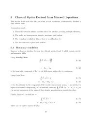
3.3 Determination of Absorption Coefficient and Band Gap - Background<br />
<strong>The</strong> absorption coefficient, α, can be determined from a simple transmission experiment. <strong>The</strong> measurement<br />
will turn out to be very simple, but we’ll consider the background in some detail.<br />
Consider the case where we have two different samples of the same material but of differing thicknesses,<br />
d 1 and d 2 . <strong>The</strong>n, from equation (36) above, the ratio of the transmission coefficients for each sample<br />
will be<br />
T 1<br />
T 2<br />
= e −α(d 1−d 2 )<br />
(41)<br />
where, from equation (29), T 1 = I 1<br />
I 0<br />
, T 2 = I 2<br />
I 0<br />
, and I 1 and I 2 are the intensities transmitted through<br />
sample 1 and sample 2 respectively. By placing sample 1 in the reference cell and sample 2 in the<br />
sample cell, one can measure the absorbance<br />
( ) I1<br />
A = log . (42)<br />
I 2<br />
However, the reference and sample beams are of different intensity, so the spectrophotometer reading<br />
is<br />
( ) T1 I 01<br />
A = log<br />
T 2 I 02<br />
(43)<br />
where I 01 and I 02 are the intensities of the beams incident on samples 1 and 2 respectively. To find<br />
one needs to take the spectrophotometer reading without the samples, which is<br />
I 01<br />
I 02<br />
9