HOTVAR⢠Hot work tool steel - Uddeholm
HOTVAR⢠Hot work tool steel - Uddeholm
HOTVAR⢠Hot work tool steel - Uddeholm

You also want an ePaper? Increase the reach of your titles
YUMPU automatically turns print PDFs into web optimized ePapers that Google loves.
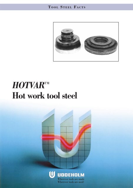
T OOL STEEL FACTS<br />
HOTVAR <br />
<strong>Hot</strong> <strong>work</strong> <strong>tool</strong> <strong>steel</strong><br />
Wherever <strong>tool</strong>s are made<br />
Wherever <strong>tool</strong>s are used
HOTVAR<br />
General<br />
HOTVAR is a high performance molybdenumvanadium<br />
alloyed hot-<strong>work</strong> <strong>tool</strong> <strong>steel</strong> which is<br />
characterized by:<br />
• High hot wear resistance<br />
• Very good high temperature properties<br />
• High resistance to thermal fatigue<br />
• Very good temper resistance<br />
• Very good thermal conductivity.<br />
Typical C Si Mn Cr Mo V<br />
analysis % 0,55 1,0 0,75 2,6 2,25 0,85<br />
Standard<br />
specification None<br />
Delivery<br />
condition Soft annealed to approx. 210 HB<br />
Colour code Red/brown<br />
IMPROVED TOOLING PERFORMANCE<br />
HOTVAR is a specially premium hot <strong>work</strong> <strong>steel</strong><br />
developed by <strong>Uddeholm</strong> to provide a very good<br />
performance in <strong>tool</strong>ing up to 650°C. The alloy<br />
elements in HOTVAR are balanced to give high<br />
hot wear resistance and good high temperature<br />
properties. HOTVAR is manufactured by special<br />
techniques.<br />
Applications<br />
HOTVAR is a hot-<strong>work</strong> <strong>tool</strong> <strong>steel</strong> suitable for applications<br />
where hot wear and/or plastic deformation<br />
are the dominating failure mechanisms.<br />
Applications and <strong>tool</strong>s of especial interest:<br />
• Warm forging, dies and punches<br />
• Roll forging, rolling segments<br />
• Rock orbital forging, punches and dies<br />
• Upset forging, clamping <strong>tool</strong>s<br />
• Progressive forging, dies<br />
• Axial closed die rolling, top and bottom dies<br />
• Cross forming, segments<br />
• <strong>Hot</strong> bending, <strong>tool</strong>s<br />
• <strong>Hot</strong> calibration, <strong>tool</strong>s<br />
• Zinc die casting, dies<br />
• Al-tube extrusion.<br />
Recommended hardness level is 54–58 HRC.<br />
For improving the wear resistance the <strong>tool</strong>s can be<br />
plasma nitrided or nitrocarburized.<br />
Properties<br />
All specimens are taken from the centre of a bar<br />
115 mm Ø (4,5”). Unless otherwise is indicated all<br />
specimens were hardened at 1050°C (1920°F),<br />
quenched in air and tempered 2 + 2 h at 575°C<br />
(1070°F) to a hardness corresponding to 56 HRC.<br />
PHYSICAL DATA<br />
Data at room and elevated temperatures.<br />
Temperature 20°C 400°C 600°C<br />
(70°F) (750°F) (1110°F)<br />
Density<br />
kg/m 3 7 800 7 700 7 600<br />
lbs/in 3 0,281 0,277 0,274<br />
Modulus of<br />
elasticity<br />
MPa 210 000 180 000 140 000<br />
psi 30,5 x 10 6 26,1 x 10 6 20,3 x 10 6<br />
Coefficient<br />
of thermal<br />
expansion per<br />
°C from 20°C – 12,6 x 10 –6 13,2 x 10 –6<br />
°F from 68°F – 7,0 x 10 –6 7,3 x 10 –6<br />
Thermal<br />
conductivity<br />
W/m °C 31 33 33<br />
Btu in (ft 2 h °F) 215 230 230<br />
MECHANICAL PROPERTIES<br />
Approximate tensile strength at room temperature.<br />
Hardness 54 HRC 56 HRC 58 HRC<br />
Tensile 2 100 MPa 2 200 MPa 2 300 MPa<br />
strength 136 tsi 142 tsi 149 tsi<br />
Rm 305 000 psi 320 000 psi 335 000 psi<br />
Yield 1 800 MPa 1 820 MPa 1 850 MPa<br />
strength 117 tsi 119 tsi 121 tsi<br />
Rp0,2 260 000 psi 265 000 psi 270 000 psi<br />
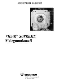
Dies for axial closed die rolling.<br />
2
HOTVAR<br />
<strong>Hot</strong> strength<br />
<strong>Hot</strong> strength in longitudinal direction.<br />
psi<br />
1000X<br />
362<br />
Rm/Rp0,2/MPa<br />
2500<br />
Z, A5%<br />
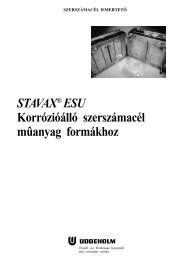
Effect of time at high temperature on hardness<br />
The softening at high temperatures and different<br />
holding times are shown below. The specimens<br />
have first been hardened and tempered to 54, 56<br />
and 58 HRC.<br />
Rm<br />
Hardness, HRC<br />
60<br />
290<br />
2000<br />
55<br />
50<br />
217<br />
1500<br />
Rp0,2<br />
45<br />
40<br />
550°C<br />
(1020°F)<br />
145<br />
1000<br />
100<br />
35<br />
72<br />
500<br />
Z<br />
50<br />
30<br />
0 1 10 100<br />
Time, hours<br />
A 5<br />
Hardness, HRC<br />
0<br />
0<br />
0<br />
0 200 400 600 800°C<br />
30 390 750 1110 1470°F<br />
60<br />
55<br />
600°C<br />
(1110°F)<br />
Temperature<br />
50<br />
45<br />
Effect of testing temperature on impact energy<br />
Charpy -V specimens, transverse direction.<br />
Impact energy<br />
ft lbs joule<br />
15 20<br />
40<br />
35<br />
30<br />
0 1 10 100<br />
Time, hours<br />
11 15<br />
7 10<br />
Hardness, HRC<br />
60<br />
55<br />
50<br />
650°C<br />
(1200°F)<br />
4 5<br />
45<br />
40<br />
35<br />
0<br />
0 100 200 300 400 °C<br />
30 210 390 570 750 °F<br />
Testing temperature<br />
30<br />
0 1 10 100<br />
Time, hours<br />
3
HOTVAR<br />
Heat treatment—<br />
general recommendations<br />
SOFT ANNEALING<br />
Protect the <strong>steel</strong> and heat through to 820°C<br />
(1500°F). Then cool in the furnace at 10°C (20°F)<br />
per hour to 600°C (1110°F), then freely in air.<br />
STRESS RELIEVING<br />
After rough machining the <strong>tool</strong> should be heated<br />
through to 650°C (1200°F), holding time 2 hours.<br />
Cool slowly to 350°C (660°F), then freely in air.<br />
HARDENING<br />
Pre-heating temperature: first step at 480–600°C<br />
(895–1110°F), second step at 850°C (1560°F).<br />
Austenitizing temperature: 1050–1070°C (1920–<br />
1960°F), normally 1050°C (1920°F) but when<br />
maximum hardness is required the normally temperature<br />
is 1070°C (1960°F).<br />
Hardness before temp.<br />
Temperature Soaking time* for Ø 25 mm (1 inch)<br />
°C °F minutes Oil Air<br />
1050 1920 30 61 ±1 59 ±1<br />
1070 1960 20 62 ±1 60 ±1<br />
* Soaking time = time at hardening temperature after the<br />
<strong>tool</strong> is fully heated through.<br />
Protect the part against decarburization and oxidation<br />
during hardening.<br />
QUENCHING MEDIA<br />
• High speed gas/circulating atmosphere<br />
• Vacuum (high speed gas with sufficient positive<br />
pressure)<br />
• Martempering bath or fluidized bed at 450–<br />
550°C (840–1020°F)<br />
• Martempering bath or fluidized bed at approx.<br />
180–220°C (360–430°F)<br />
• Warm oil, about 80°C (175°F).<br />
Note. 1: Temper the <strong>tool</strong> as soon as its temperature<br />
reaches 50–70°C (120–160°F).<br />
Note. 2: In order to obtain the optimum properties<br />
for the <strong>tool</strong>, the cooling rate should be fast but not<br />
at a level that gives excessive distortion or cracks.<br />
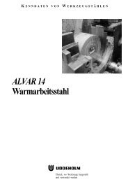
CCT -graph<br />
Austenitizing temperature 1050°C (1920°F). Holding time 30 minutes.<br />
°F<br />
2000<br />
1800<br />
1600<br />
1400<br />
1200<br />
1000<br />
800<br />
600<br />
400<br />
200<br />
°C<br />
1100<br />
1000<br />
900<br />
800<br />
700<br />
600<br />
500<br />
400<br />
300<br />
200<br />
100<br />
A c1<br />
= A890°C<br />
(1630°F) C1 = 890°C (1630°F)<br />
Ac<br />
C1s = 800°C (1470°F)<br />
= 800°C<br />
(1470°F)<br />
Pearlite<br />
Cooling<br />
Carbides<br />
Bainite<br />
M s<br />
M f<br />
Martensite<br />
1 2 3 4 5 6 7 8<br />
1<br />
1 10 100 10001 10 000 100 000 Seconds<br />
9<br />
curve Hardness T 800–500<br />
No. HV 10 (sec)<br />
1 772 1<br />
2 734 140<br />
3 715 280<br />
4 707 450<br />
5 690 630<br />
6 548 1390<br />
7 473 5215<br />
8 464 8360<br />
9 351 19400<br />
1 10 100<br />
1 1000<br />
Minutes<br />
Minutes<br />
1 10 100 Hours<br />
Air Air cooling cooling of bars of<br />
0,2 0.2<br />
1,5 1.5<br />
10 90 600<br />
Ø mm bars, Ø mm<br />
0.0079<br />
0.059<br />
0.394 3.54 23.6 inch<br />
0,008 0,06 0,4 3,6 23,5 inch<br />
4
HOTVAR<br />
Hardness, grain size and retained austenite as function<br />
of austenitizing temperature.<br />
Samples Ø 25 mm (1 inch).<br />
Grain<br />
size<br />
ASTM<br />
Hardness, HRC<br />
10 64<br />
8<br />
6<br />
4<br />
2<br />
0<br />
TEMPERING<br />
Choose the tempering temperature according to<br />
the hardness required by reference to tempering<br />
graph. Temper minimum twice with intermediate<br />
cooling to room temperature. Holding time at temperature<br />
minimum 2 hours.<br />
Tempering graph<br />
Hardness, HRC<br />
60<br />
58<br />
56<br />
62<br />
60<br />
58<br />
56<br />
HRC Oil<br />
Grain size<br />
Retained austenite<br />
54<br />
0<br />
1050 1060 1070 1080°C<br />
1920 1940 1960 1980°F<br />
Austenitizing temperature<br />
1070°C<br />
(1960°F)<br />
Retained austenite %<br />
HRC Air<br />
6<br />
4<br />
2<br />
DIMENSIONAL CHANGES DURING<br />
HARDENING AND TEMPERING<br />
During hardening and tempering the die is exposed<br />
to thermal as well as transformation<br />
stresses. This will inevitably result in dimensional<br />
changes and in the worse case distortion. It is<br />
therefore recommended to always leave enough<br />
machining allowance after machining before the<br />
die is hardened and tempered. Normally the size in<br />
the largest direction will shrink and the size in the<br />
smallest direction might increase, but this is also a<br />
matter of the die size, the die design as well as the<br />
cooling rate after hardening.<br />
For HOTVAR it is recommend to leave a machining<br />
allowance of 0,4 per cent of the dimension in<br />
length, width and thickness.<br />
NITRIDING AND NITROCARBURIZING<br />
Nitriding and nitrocarburizing result in a hard<br />
surface layer which is very resistant to wear and<br />
erosion. The nitrided layer is, however, brittle and<br />
may crack or spall when exposed to mechanical or<br />
thermal shock, the risk increases with layer thickness.<br />
Before nitriding, the <strong>tool</strong> should be hardened<br />
and tempered at a temperature at least 50°C<br />
(90°F) above the nitriding temperature.<br />
In general, plasma nitriding is the preferred<br />
method because of better control over nitrogen<br />
potential. Plasma nitriding at 480°C (895°F) in a<br />
75% hydrogen/25% nitrogen mixture result in a<br />
surface hardness of about 1000 HV 0,2 .<br />
HOTVAR can also be nitrocarburized in either gas<br />
or salt bath. The surface hardness after nitrocarburizing<br />
is about 900 HV 0,2 .<br />
DEPTH OF NITRIDING<br />
54<br />
52<br />
50<br />
48<br />
46<br />
1050°C<br />
(1920°F)<br />
Depth<br />
Process Time mm inch<br />
Plasma nitriding 10 0,18 0,0070<br />
at 480°C (895°F) 30 0,27 0,0106<br />
Nitrocarburizing<br />
–in gas<br />
at 580°C (1075°F) 2,5 0,20 0,0080<br />
–in salt bath<br />
at 580°C (1075°F) 1 0,13 0,0050<br />
44<br />
550 575 600 625°C<br />
1020 1070 1110 1160°F<br />
Tempering temperature (2+2 hours)<br />
It should be noted that HOTVAR exhibits better<br />
nitridability than AISI H13. For this reason, the<br />
nitriding times for HOTVAR should be shortened<br />
in relation to H13, otherwise there is a considerable<br />
risk that the case depth will be too great.<br />
Tempering at 250°C (485°F), 2 + 2h gives a hardness<br />
of 56–58 HRC.<br />
5
HOTVAR<br />
Machining<br />
recommendations<br />
The cutting data below, valid for HOTVAR in soft<br />
annealed condition, are to be considered as guiding<br />
values which must be adapted to existing local<br />
conditions. More detailed information can be<br />
found in <strong>Uddeholm</strong> “Cutting Data Recommendations”.<br />
TURNING<br />
Turning<br />
Turning<br />
with carbide with high<br />
Cutting data<br />
speed <strong>steel</strong><br />
parameters Rough turning Fine turning Fine turning<br />
Cutting<br />
speed (v c<br />
)<br />
m/min. 140–160 160–180 25<br />
f.p.m. 455–520 520–590 80<br />
Feed (f)<br />
mm/r 0,3–0,6 –0,3 –0,3<br />
i.p.r. 0,01–0,024 –0,01 –0,01<br />
Depth of cut<br />
(a p<br />
)<br />
mm 2–6 –2 –2<br />
inch 0,08–0,24 –0,08 –0,08<br />
Carbide designation<br />
ISO P20–P30 P10 –<br />
US C6–C5 C7 –<br />
Coated Coated<br />
carbide carbide or<br />
cermet<br />
DRILLING<br />
High speed <strong>steel</strong> twist drill<br />
Drill diameter Cutting<br />
Ø speed (v c ) Feed (f)<br />
mm inch m/min. f.p.m. mm/r i.p.r.<br />
MILLING<br />
Face and square shoulder milling<br />
Milling<br />
Milling<br />
with carbide with high<br />
Cutting data<br />
speed <strong>steel</strong><br />
parameters Rough milling Fine milling Fine milling<br />
Cutting speed<br />
(v c<br />
) m/min. 140–180 180–220 80<br />
f.p.m. 455–590 590–720 100<br />
Feed (f z )<br />
mm/tooth 0,2–0,4 0,1–0,2 –0,1<br />
inch/tooth 0,008–0,016 0,003–0,007 –0,004<br />
Depth of cut<br />
(a p ) mm 2–5 –2 –2<br />
inch 0,08–0,2 –0,08 –0,08<br />
Carbide designation<br />
ISO P20–P40 P10 –<br />
US C6–C5 C7 –<br />
Coated Coated<br />
carbide carbide or<br />
cermet<br />
End milling<br />
Type of milling<br />
Carbide<br />
Cutting data Solid indexable High<br />
parameters carbide insert speed <strong>steel</strong><br />
Cutting<br />
speed (v c )<br />
m/min. 65 120–160 25 1)<br />
f.p.m. 210 390–520 80 1)<br />
Feed (f z )<br />
mm/tooth 0,03–0,2 2) 0,08–0,2 2) 0,05–0,35 2)<br />
inch/tooth 0,001–0,008 2) 0,003–0,008 2) 0,002–0,014 2)<br />
Carbide<br />
designation<br />
ISO K10, P40 P20–P30 –<br />
US C3–C5 C6–C5 –<br />
1)<br />
For coated HSS end mill v c ≈ 40 m/min. (130 f.p.m.).<br />
2)<br />
Depending on radial depth of cut and cutter diameter.<br />
–5 –3/16 14* 46* 0,08–0,20 0,003–0,008<br />
5–10 3/16–3/8 14* 46* 0,20–0,30 0,008–0,012<br />
10–15 3/8–5/8 14* 46* 0,30–0,35 0,012–0,014<br />
15–20 5/8–3|4 14* 46* 0,35–0,40 0,014–0,016<br />
*)<br />
For coated HSS drill v c ~20 m/min. (66 f.p.m.).<br />
GRINDING<br />
General grinding wheel recommendation is given<br />
below. More information can be found in the <strong>Uddeholm</strong><br />
publication “Grinding of Tool Steel”.<br />
Carbide drill<br />
Type of drill<br />
Cutting data Indexable Solid Brazed<br />
parameters insert carbide carbide 1)<br />
Cutting<br />
speed (v c )<br />
m/min. 160–200 65 55<br />
f.p.m. 520–650 215 180<br />
Feed (f)<br />
mm/r 0,05–0,25 2) 0,10–0,25 2) 0,15–0,25 2)<br />
i.p.r. 0,002–0,010 2) 0,004–0,010 2) 0,006–0,010<br />
Type of grinding<br />
Face grinding<br />
straight wheel<br />
Face grinding<br />
segment<br />
Cylindrical grinding<br />
Internal grinding<br />
Profile grinding<br />
Wheel recommendation<br />
Soft annealed<br />
condition<br />
A 46 HV<br />
A 24 GV<br />
A 46 LV<br />
A 46 JV<br />
A 100 LV<br />
Hardened<br />
condition<br />
A 46 GV<br />
A 36 GV<br />
A 60 JV<br />
A 60 IV<br />
A 120 JV<br />
1) Drill with internal cooling channels and brazed carbide<br />
tip.<br />
Depending on drill diameter.<br />
6
HOTVAR<br />
Electrical-discharge<br />
machining<br />
If spark-erosion, EDM, is performed in the hardened<br />
and tempered condition, the white re-cast<br />
layer should be removed mechanically e.g. by<br />
grinding or stoning. The <strong>tool</strong> should then be given<br />
an additional temper at approx. 25°C (50°F) below<br />
the previous tempering temperature.<br />
More detailed information can be found in the<br />
<strong>Uddeholm</strong> publication “EDM of Tool Steel”.<br />
Welding<br />
Good results when welding <strong>tool</strong> <strong>steel</strong> can be<br />
achieved if proper precautions are taken during<br />
welding (elevated <strong>work</strong>ing temperature, joint<br />
preparation, choice of consumables and welding<br />
procedure).<br />
Welding method TIG MMA<br />
Working<br />
temperature 325–375°C 325–375°C<br />
QRO 90<br />
Filler metals TIG-WELD QRO 90 WELD<br />
Hardness after<br />
welding 50–55 HRC 50–55 HRC<br />
Heat treatment after welding<br />
Hardened Temper at 20°C (40°F) below the<br />
condition<br />
original tempering temperature.<br />
Soft annealed Soft anneal the material at 820°C<br />
condition<br />
(1500°F) in protected atmosphere.<br />
Then cool in the furnace at 10°C<br />
(20°F) per hour to 650°C (1200°F)<br />
then free in air.<br />
More detailed information can be found in the<br />
<strong>Uddeholm</strong> brochure “Welding of Tool Steel”.<br />
Further information<br />
Contact your local <strong>Uddeholm</strong> office for further<br />
information on the selection, heat treatment, application<br />
and availability of <strong>Uddeholm</strong> <strong>tool</strong> <strong>steel</strong>s.<br />
This information is based on our present state of knowledge and is<br />
intended to provide general notes on our products and their uses.<br />
It should not therefore be construed as a warranty of specific<br />
properties of the products described or a warranty for fitness for a<br />
particular purpose.<br />
7