Analogue instruments - Ulrichmatterag.ch
Analogue instruments - Ulrichmatterag.ch
Analogue instruments - Ulrichmatterag.ch

Create successful ePaper yourself
Turn your PDF publications into a flip-book with our unique Google optimized e-Paper software.
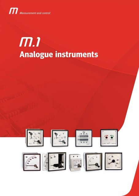
Measurement and control<br />
<strong>Analogue</strong> <strong>instruments</strong>
<strong>Analogue</strong> <strong>instruments</strong><br />
<strong>Analogue</strong> <strong>instruments</strong><br />
Introduction ............................................................................................. 4<br />
Product selection table .................................................................................... 7<br />
EC / EM / EZC / EC FA / CEC 96<br />
Moving iron ammeters (AC) ................................................................................ 8<br />
EC / EM / EZC / ECF / EC FN / CEC 96<br />
Moving iron voltmeters (AC). ..............................................................................13<br />
BC / BM / CBC 96<br />
Moving-coil ammeter (DC) ................................................................................18<br />
BC / BM / CBC 96<br />
Moving-coil voltmeter (DC). ...............................................................................21<br />
BC / BM / ZC<br />
<strong>Analogue</strong> indicator to measure a process signal ............................................................. 24<br />
MC / MMC / EMC<br />
Power demand meters. <strong>Analogue</strong> indicator to measure alternating current and its maximeter ....................... 27<br />
HC / HM / HZC<br />
Pointer Frequency meters ................................................................................30<br />
HLC<br />
Reed Frequency meters ..................................................................................32<br />
WMC / WTC<br />
Wattmeters. <strong>Analogue</strong> indicator to measure power ........................................................... 34<br />
YMC / YTC<br />
Varmeters. <strong>Analogue</strong> indicator to measure the reactive energy ................................................. 39<br />
FEM / FETC / FMZ / FTZ<br />
Electronic phase-meters ..................................................................................43<br />
PIC A / PIC B / PIC E<br />
Induction phase-meters ..................................................................................46<br />
PGR<br />
Bidirectional protection wattmeters ........................................................................48<br />
2 EC / 2 HC / 2 HLC<br />
Syn<strong>ch</strong>ronisation and marine applications equipment ......................................................... 50<br />
SMC / STC / UC / CUC<br />
Syn<strong>ch</strong>ronisation and marine applications equipment ......................................................... 53<br />
Syn<strong>ch</strong>ro MAX / Syn<strong>ch</strong>ro MAX PID<br />
Syn<strong>ch</strong>ronisation and marine applications equipment ......................................................... 56<br />
M1-2
Measurement and control<br />
MEG - 1000<br />
Insulation resistance meter ...............................................................................59<br />
CH<br />
Hours run meter .........................................................................................61<br />
Accessories ............................................................................................63<br />
M1-3
<strong>Analogue</strong> <strong>instruments</strong><br />
<strong>Analogue</strong> <strong>instruments</strong><br />
In many applications, su<strong>ch</strong> as control<br />
and distribution panels, it is important to<br />
control the installation quickly and visually,<br />
with no need to interpret data to detect<br />
the installation's status.<br />
CIRCUTOR offers a solution to these<br />
needs with this range of products. <strong>Analogue</strong><br />
indicators are essential to display<br />
an instantaneous electrical value with a<br />
needle that moves through a graduated<br />
scale.<br />
M.1<br />
Definition<br />
The main operation of these <strong>instruments</strong><br />
is provided by the type of<br />
measurement system used, either a<br />
ferromagnetic system to measure alternating<br />
current or a magneto-electric<br />
system to measure direct current.<br />
CIRCUTOR offers equipment for both<br />
systems. However, most systems are<br />
generally used to measure alternating<br />
current.<br />
In general, analogue <strong>instruments</strong> are<br />
used because the interpretation of<br />
electrical parameters is quicker and<br />
more visual. Therefore, in this case the<br />
user simply looks at the position of the<br />
needle and does not have to interpret a<br />
number on a digital display.<br />
FERROMAGNETIC OR MAGNETO-<br />
ELECTRIC<br />
Electric current is directly translated by<br />
a measurement element that moves the<br />
needle. There are two types of measurement<br />
elements<br />
Ferromagnetic (AC)<br />
The ferromagnetic indicator is composed<br />
of a coil that transmits the current<br />
measured, with a fixed iron element<br />
and moving iron element in its centre,<br />
connected to the instrument's axis and<br />
needle. The set moves by the repulsion<br />
effect produced by the magnetic field<br />
between both iron elements and the arc<br />
depends on the current transmitted by<br />
M1-4
<strong>Analogue</strong> <strong>instruments</strong><br />
the coil. This system is used to measure<br />
AC and DC voltage and current between<br />
15 and 100 Hz and it measures the root<br />
mean square of alternating current. It<br />
can not be used to measure rectified<br />
and unfiltered AC currents.Magnetoelectric<br />
(DC)<br />
The magneto-electric indicator is composed<br />
of a permanent central magnet,<br />
surrounded by a magnetic casing that<br />
guarantees the insensitivity to the exterior<br />
magnetic field and there is a moving<br />
coil between both, where the needle<br />
is fixed. Two spiral springs create<br />
the antagonistic pair to move the needle<br />
on the scale zero. This system is<br />
used to measure DC currents and voltages,<br />
measuring mean values.<br />
Electrical and me<strong>ch</strong>anical features<br />
Insulation voltage<br />
2 kV, 50 Hz, 1min between the me<strong>ch</strong>anism<br />
and the box and between electrically<br />
insulated terminals.<br />
Permanent overloads<br />
Voltage circuits: 1.2 U n<br />
Current circuits: 1.2 I n<br />
(1.5 I n<br />
for moving iron)<br />
Short duration overloads<br />
Voltage circuits:<br />
2 U n<br />
during 5 s<br />
Current circuits:<br />
5 I n<br />
during 30 s<br />
10 I n<br />
during 5 s<br />
40 I n<br />
during 1 s<br />
Relays<br />
Contacts: NO / NC<br />
Interrupting power: 230 V ac,<br />
8 A / 30 V dc, 5 A resistive load<br />
Factors that influence the Class<br />
Assembly position<br />
All <strong>instruments</strong> will be assembled in<br />
a vertical position. They can be supplied<br />
for vertical or horizontal assembly,<br />
on demand. The tolerance is ±5º.<br />
Room temperature<br />
The effects of temperature on the Class<br />
depend on the scope of the measurement.<br />
In general, <strong>instruments</strong> maintain<br />
their Class between +10 and +30ºC.<br />
This interval can be lower for particularly<br />
low measurement scopes. In these<br />
cases, the limit values are indicated on<br />
the scale.<br />
The <strong>instruments</strong> can be adjusted for<br />
temperatures out of the interval mentioned<br />
above, on demand.Temperature<br />
limits Measurement <strong>instruments</strong> and<br />
their accessories support variations in<br />
temperature between -25 and +40 ºC<br />
(55 ºC in the tropicalized version) with<br />
no permanent defects.<br />
Relative humidity<br />
The Class is maintained within the 25<br />
and 80 % non-condensing relative humidity<br />
interval.<br />
Magnetic field<br />
All <strong>instruments</strong> maintain their Class under<br />
the influence of an exterior magnetic<br />
field with a value of ≤ 0.5 MV.<br />
Ferromagnetic support<br />
The nature and thickness of the panel's<br />
plate does not affect the Class,<br />
with the exception of highly sensi-<br />
M1-5
<strong>Analogue</strong> <strong>instruments</strong><br />
tive <strong>instruments</strong>. In these cases, the<br />
scales are marked with the Fe symbol,<br />
followed by the plate's thickness.<br />
Auxiliary power supply<br />
The tolerance accepted for the nominal<br />
auxiliary power supply values is:<br />
voltage: -15 ... +10 %<br />
frequency: 45 ... 65 Hz<br />
Vibrations<br />
The <strong>instruments</strong> and their accessories<br />
support a minimum vibration with an<br />
amplitude of ±0.25 mm and a frequency<br />
of 50 cycles. Said vibration is equivalent<br />
to the application of an acceleration<br />
equal to 2.5 g to the three perpendicular<br />
axes during 20 minutes.<br />
Degree of protection<br />
Under normal operating conditions, the<br />
instrument boxes have an IP 52 protection<br />
degree and terminals have an IP 00<br />
protection degree. Optionally, boxes are<br />
offered with an IP 54 or IP 55 protection<br />
degree and their terminals with an IP 20<br />
protection degree.<br />
Pointers<br />
In accordance with DIN 43802.<br />
With tube or blade pointers, on demand<br />
(Fig. 1)<br />
Tropicalization (TROP)<br />
Under TROP operation, and in accordance<br />
with the DIN 40040 Standard, the<br />
<strong>instruments</strong> are protected against corrosive<br />
environments and support temperatures<br />
between -25 and +55 ºC, with<br />
a non-condensing relative humidity of<br />
95 %. Said humidity percentage is stated<br />
for a maximum temperature of 30 ºC<br />
and 30 days a year; during the rest of<br />
the year, the humidity must not exceed<br />
75 %.Within this type of operation, the<br />
<strong>instruments</strong> can be adjusted for reference<br />
temperature values above 20 ºC.<br />
In these cases, the scales are marked<br />
with TROP, followed by the temperature<br />
value at whi<strong>ch</strong> they are adjusted.<br />
resting position does not exceed ±2 %<br />
of the scale length.<br />
Boxes<br />
The boxes and frames of all <strong>instruments</strong><br />
are made with self-extinguishing ABS<br />
material, in compliance with UL 94, and<br />
with a high resistance to impacts.<br />
The box and frame dimensions comply<br />
with the DIN 43700 and DIN 43718<br />
Standards, respectively. Bases are<br />
made with self-extinguishing reinforced<br />
PPO, in compliance with UL<br />
94, with a high resistance to impacts<br />
and a maximum electrical insulation.<br />
Standards<br />
IEC 51, VDE 410, DIN 43780, BS 89,<br />
UL 94, EN 60051<br />
Certificates<br />
Lloyd’s Register of Shipping (Ask for different<br />
types).<br />
Scales<br />
In accordance with the Standards:<br />
DIN 43701 for scale end values.<br />
DIN 43802 to assess divisions. The divisions<br />
and numbering of standardised<br />
scopes follow the examples on Fig.2<br />
and 3.<br />
The scale end values above 1000 are<br />
stated in thousands (k).<br />
Chokes<br />
The <strong>instruments</strong> and their accessories<br />
support five impacts, with an acceleration<br />
of 15 g, applied in the direction of<br />
the three perpendicular axes.<br />
Zero correction<br />
The regulation of adjustment lengths of<br />
the zero corrector on both sides of the<br />
M1-6
<strong>Analogue</strong> <strong>instruments</strong><br />
Product selection table<br />
System<br />
measurement<br />
Fixing<br />
Ammeters<br />
Specifications<br />
Voltmeters<br />
Type<br />
Process<br />
indicators<br />
Range<br />
Size<br />
Power demand<br />
meters<br />
Class<br />
Scale angle<br />
Scale extension<br />
Reed<br />
HM<br />
BM<br />
HM<br />
BM<br />
BM<br />
Milliammeter EC 100..0.600 mA 48 x 48, 72 x 72,<br />
90º<br />
EC<br />
5...100 A,.../5A 96 x 96, 144 x 144<br />
P2<br />
-<br />
Panel<br />
EZC<br />
.../5A<br />
240º<br />
72 x 72, 96 x 96<br />
With swit<strong>ch</strong> EC FA .../5A<br />
P1<br />
With relays CEC .../5A 96 x 96<br />
1,5<br />
DIN rail - EM 45 5...60 A, .../5A 85 x 52 P2<br />
48 x 48, 72 x 72,<br />
90º<br />
- BC 5...60 A, .../60 mV<br />
Panel<br />
96 x 96, 144 x 144<br />
P1<br />
With relays CBC .../60 mV 96 x 96<br />
DIN rail - BM 45 5...60 A, .../60 mV 85 x 52<br />
Panel<br />
-<br />
EC<br />
EZC<br />
150 ... 600 V, .../110 V<br />
250 V, 500 V<br />
With swit<strong>ch</strong> EC F 150 ... 600 V<br />
48 x 48, 72 x 72,<br />
96 x 96, 144 x 144<br />
72 x 72, 96 x 96<br />
With relays CEC 150 ... 600 V, .../110 V 96 x 96<br />
DIN rail - EM 45 300 V, 500 V, .../110 V 85 x 52<br />
Panel<br />
- BC 0..0.600 V<br />
48 x 48, 72 x 72,<br />
96 x 96, 144 x 144<br />
With relays CBC .../60 mV 96 x 96<br />
DIN rail - BM45 15..0.150 V 85 x 52<br />
Panel<br />
-<br />
BC<br />
ZC<br />
0...10 V, 0/4... 20 mA<br />
0...10 V, 4... 20 mA,<br />
.../60 mV<br />
1,5<br />
48 x 48, 72 x 72,<br />
96 x 96, 144 x 144 1,5<br />
DIN rail BM 0...10 V, 0/4... 20 mA 85 x 52 90º<br />
- Panel<br />
Bimetallic<br />
MC<br />
90º<br />
240º<br />
90º<br />
P1<br />
P2<br />
P1<br />
90º P2<br />
Bimetallic + HM EMC ... / 5 A<br />
P2<br />
- DIN rail Bimetallic MMC 45 85 x 52 3 P1.2<br />
Pointer<br />
Panel<br />
- HC<br />
48 x 48, 72 x 72,<br />
96 x 96, 144 x 144<br />
- HZC 96 x 96, 144 x 144 240º<br />
DIN rail - HM<br />
45...65 depending on<br />
the type<br />
85 x 52 0,5 90<br />
240º<br />
90º<br />
P1<br />
P1.2<br />
-<br />
Reeds<br />
Panel - HLC<br />
72 x 72, 96 x 96,<br />
144 x 144<br />
-<br />
Watt-meter<br />
Varmeter<br />
Phase-meters<br />
Electronic<br />
Induction<br />
Panel<br />
Panel<br />
Panel<br />
Single-phase WMC<br />
Three-phase WTC<br />
400 V, .../5 A 96 x 96, 144 x 144 1,5 90º P1<br />
Single-phase YMC<br />
Three-phase YTC<br />
400 V, .../5 A 96 x 96, 144 x 144 1,5 90º P1<br />
Single-phase FEMC<br />
90º<br />
Three-phase FETC<br />
cos ϕ 0.5 - 1 - 0.5<br />
Single-phase FMZ<br />
240º<br />
Three-phase FTZ<br />
96 x 96, 144 x 144 1,5<br />
P1<br />
Single-phase PIC cos ϕ 0 - 1 - 0<br />
90º<br />
Three-phase PIC cos ϕ 0 - 1 - 0<br />
M1-7
<strong>Analogue</strong> <strong>instruments</strong><br />
Moving iron ammeters (AC)<br />
Moving-coil<br />
Ammeter<br />
<strong>Analogue</strong> indicator to measure<br />
alternating current<br />
Description<br />
}}<br />
No need for auxiliary power supply, only<br />
the CEC 96 type.<br />
}}<br />
DIN boxes with dimensions: 48, 72, 96<br />
and 144.<br />
}}<br />
Precision class 1.5<br />
}}<br />
Measurement in true root mean square<br />
100 mA ... 100 A<br />
}}<br />
Ex<strong>ch</strong>angeable scales for EC48, EC72,<br />
EC96, EM 45, EC 72 FA, EC 96 FA<br />
}}<br />
The alarm system can be fully configured<br />
for CEC 96<br />
Application<br />
In alternating current applications, to control<br />
the state of the current quickly and visually.<br />
Features<br />
EC EM EZC EC FA CEC 96 with 2 relays<br />
Auxiliary power supply<br />
230 V ac<br />
Consumption - 2.5 V·A<br />
Frequency - 40 ... 90 Hz<br />
Input circuit<br />
Consumption 0.3 ... 1.5 V·A 0.2 V·A<br />
Frequency 20 ... 100 Hz 45 ... 65 Hz<br />
1.2 I n<br />
permanent<br />
Overloads<br />
5 I n<br />
during 30 s<br />
10 I n<br />
during 5 s<br />
1.2 I n<br />
permanent<br />
40 I n<br />
during 1 s<br />
Class<br />
1.5 % FS<br />
Ambient conditions<br />
Operating temperature +10 ... +30 ºC + 5 ... +55 ºC<br />
Limit temperature - 25 ... +40 ºC -25 ... +70 ºC<br />
Altitude<br />
2000 m<br />
Build features<br />
Dimensions<br />
Weight<br />
See the following table<br />
See the following table<br />
Type of box panel DIN rail panel panel panel<br />
Degree of protection:<br />
Front panel<br />
Terminals<br />
Insulation voltage<br />
Standards<br />
IP 52<br />
IP 00<br />
2 kV, 50 Hz, 1 min, between the me<strong>ch</strong>anism<br />
and the box<br />
BS 89, EN 60051, IEC 144, UL 94,<br />
DIN 43780, IEC 51, UNE 21318, CE<br />
IP 52<br />
IP 20<br />
3 kV , 50 Hz, 1min<br />
IEC 51, IEC 1010, IEC 529,<br />
IEC 255, IEC 278, IEC 414,<br />
IEC 144, LLOYD'S<br />
(TEST. ESP. No. 1)<br />
M1-8
<strong>Analogue</strong> <strong>instruments</strong><br />
Moving iron ammeters (AC)<br />
Moving iron ammeter<br />
<strong>Analogue</strong> indicator to measure<br />
alternating current<br />
References<br />
Ammeters, 90º<br />
Type EC 48 EC 72 EC 96 EC 144 EM 45<br />
Class 1,5<br />
Scale (mm)<br />
Dimensions (mm)<br />
a<br />
b<br />
c<br />
48<br />
48<br />
66,2<br />
72<br />
72<br />
49,2<br />
90º , P2<br />
96<br />
96<br />
49,2<br />
144<br />
144<br />
71,8<br />
85<br />
52<br />
65<br />
Weight (g) 85 180 220 430 142<br />
mA<br />
100 M10111 M10121 M10131 M10142 M10151<br />
150 M10112 M10122 M10132 M10142 M10152<br />
250 M10114 M10124 M10134 M10144 M10154<br />
300 M10115 M10125 M10135 M10145 M10155<br />
400 M10116 M10126 M10136 M10146 M10156<br />
500 M10117 M10127 M10137 M10147 M10157<br />
600 M10118 M10128 M10138 M10148 M10158<br />
A<br />
5 M10212 M10222 M10232 M10242 M10252<br />
10 M10213 M10223 M10233 M10243 M10253<br />
15 M10214 M10224 M10234 M10244 M10254<br />
20 M10215 M10225 M10235 M10245 M10255<br />
25 M10216 M10226 M10236 M10246 M10256<br />
30 M10217 M10227 M10237 M10247 M10257<br />
40 M10218 M10228 M10238 M10248 M10258<br />
50 M10219 M10229 M10239 M10249 M10259<br />
60 M1021A M1022A M1023A M1024A M1025A<br />
75 - M1022B M1023B M1024B -<br />
100 - M1022C M1023C M1024C -<br />
.../5 A (*) M10210 M10220 M10230 M10240 M10250<br />
Ammeters, 240º<br />
Ammeters with<br />
phase swit<strong>ch</strong><br />
Ammeters<br />
with 2 relays<br />
Type EZC 72 EZC 96 EC 72 FA EC 96 FA CEC 96<br />
Accuracy<br />
class<br />
Scale (mm) 240º, P2 90 or , P1 90 or , P2<br />
Dimensions (mm)<br />
a<br />
b<br />
c<br />
72<br />
72<br />
49,2<br />
96<br />
96<br />
49,2<br />
72<br />
72<br />
49,2<br />
1,5<br />
96<br />
96<br />
49,2<br />
96<br />
96<br />
85,3<br />
Weight (g) 180 220 180 220 435<br />
mA<br />
.../5 A (*) M10920 M10930 M10521 M10531 M14810<br />
* EZC 72 / EZC96:<br />
Scale included, indicate the transformer ratio<br />
.../1 A , on demand<br />
Different settings, on demand<br />
* EC 72 FA / EC96 FA:<br />
Scale not included<br />
Ex<strong>ch</strong>angeable scales (see tables)<br />
.../1 A , on demand<br />
Different settings, on demand<br />
* CEC 96:<br />
Scale included, indicate the transformer ratio<br />
Ex<strong>ch</strong>angeable scales (see tables)<br />
.../1 A , on demand<br />
*Scale is not included, except in EC144 (equipment + scale included,<br />
indicate transformer ratio).<br />
*For ex<strong>ch</strong>angeable scales, see Tables.<br />
* .../1 A on demand<br />
* Different settings, on demand.<br />
M1-9
<strong>Analogue</strong> <strong>instruments</strong><br />
Moving iron ammeters (AC)<br />
Moving iron ammeter<br />
<strong>Analogue</strong> indicator to measure<br />
alternating current<br />
References<br />
Ex<strong>ch</strong>angeable scales, Moving Iron Ammeters<br />
Type SEC 48 SEC 72 SEC 96 SEM 45 SEC 72 FA SEC 96 FA<br />
Equipment EC 48 EC 72 EC 96 EM 45 EC 72 FA EC 96 FA<br />
A<br />
5/5 M102Z2 M102Y2 M102X2 - - -<br />
10/5 M102Z3 M102Y3 M102X3 - - -<br />
15/5 M102Z4 M102Y4 M102X4 - - -<br />
20/5 M102Z5 M102Y5 M102X5 - - -<br />
25/5 M102Z6 M102Y6 M102X6 - - -<br />
30/5 M102Z7 M102Y7 M102X7 - - -<br />
40/5 M102Z8 M102Y8 M102X8 - - -<br />
50/5 M102Z9 M102Y9 M102X9 M105X9 M105Y9 M105X9<br />
60/5 M102ZA M102YA M102XA M105XA M105YA M105XA<br />
75/5 M102ZB M102YB M102XB M102VB M105YB M105XB<br />
100/5 M102ZC M102YC M102XC M102VC M105YC M105XC<br />
125/5 M102ZD M102YD M102XD M102VD M105YD M105XD<br />
150/5 M102ZE M102YE M102XE M102VE M105YE M105XE<br />
200/5 M102ZF M102YF M102XF M102VF M105YF M105XF<br />
250/5 M102ZG M102YG M102XG M102VG M105YG M105XG<br />
300/5 M102ZH M102YH M102XH M102VH M105YH M105XH<br />
400/5 M102ZJ M102YJ M102XJ M102VJ M105YJ M105XJ<br />
500/5 M102ZK M102YK M102XK M102VK M105YK M105XK<br />
600/5 M102ZL M102YL M102XL M102VL M105YL M105XL<br />
750/5 M102ZM M102YM M102XM M102VM M105YM M105XM<br />
800/5 M102ZN M102YN M102XN M102VN M105YN M105XN<br />
1 000/5 M102ZP M102YP M102XP M102VP M105YP M105XP<br />
1 200/5 M102ZQ M102YQ M102XQ M102VQ M105YQ M105XQ<br />
1 500/5 M102ZR M102YR M102XR M102VR M105YR M105XR<br />
2 000/5 M102ZS M102YS M102XS M102VS M105YS M105XS<br />
2 500/5 M102ZT M102YT M102XT M102VT M105YT M105XT<br />
3 000/5 M102ZU M102YU M102XU M102VU M105YU M105XU<br />
4 000/5 M102ZV M102YV M102XV M102VV M105YV M105XV<br />
5 000/5 M102ZW M102YW M102XW M102VW M105YW M105XW<br />
M1-10
<strong>Analogue</strong> <strong>instruments</strong><br />
Moving iron ammeters (AC)<br />
Moving iron ammeter<br />
<strong>Analogue</strong> indicator to measure<br />
alternating current<br />
Coding table<br />
M 1 X X X X 0 0 X X X<br />
M 1 X X X X 0 0 X<br />
Code<br />
Setting<br />
Internal<br />
Code<br />
Standard 2P 0<br />
1P 1<br />
5P 6<br />
EC and EM<br />
Milliammeters<br />
Code<br />
Setting<br />
Internal<br />
Code<br />
Standard 2P 0<br />
1P 1<br />
5P 6<br />
Current<br />
Standard (... / 5 A) 0<br />
EC and EZC Ammeters<br />
input<br />
Scales (*)<br />
... / 1 A 1<br />
1 1<br />
5 2<br />
10 3<br />
15 4<br />
20 5<br />
25 6<br />
30 7<br />
40 8<br />
50 9<br />
60 A<br />
75 B<br />
100 C<br />
125 D<br />
150 E<br />
200 F<br />
250 G<br />
300 H<br />
EC Scales and<br />
Ammeters and EM<br />
scales<br />
Ammeters and EC<br />
FA scales<br />
M 1 X X X X 0 0 X X<br />
Code<br />
Setting<br />
Current<br />
input<br />
Internal<br />
Code<br />
Standard 2P 0<br />
1P 1<br />
5P 6<br />
Standard (.../ 5 A) 0<br />
... / 1 A 1<br />
M 1 X X X X 0 0 X X<br />
Code<br />
Setting<br />
Current<br />
input<br />
Internal<br />
Code<br />
Standard 1P 0<br />
5P 6<br />
Standard (.../ 5 A) 0<br />
... / 1 A 1<br />
400 J<br />
500 K<br />
600 L<br />
750 M<br />
800 N<br />
1000 P<br />
1200 Q<br />
1500 R<br />
2000 S<br />
2500 T<br />
3000 U<br />
4000 V<br />
5000 W<br />
CEC Ammeters<br />
M 1 X X X X 0 0 X X<br />
Internal<br />
Code<br />
Code<br />
100 C<br />
125 D<br />
150 E<br />
200 F<br />
250 G<br />
300 H<br />
400 J<br />
Scale<br />
500 K<br />
600 L<br />
750 M<br />
800 N<br />
1000 P<br />
1200 Q<br />
2000 R<br />
2500 S<br />
Current Standard (.../ 5 A) 0<br />
input<br />
... / 1 A 1<br />
M1-11
<strong>Analogue</strong> <strong>instruments</strong><br />
Moving iron ammeters (AC)<br />
Moving iron ammeter<br />
<strong>Analogue</strong> indicator to measure<br />
alternating current<br />
Dimensions<br />
EC<br />
EZC<br />
Type Fig. EC a b c d e<br />
48 mm 1 -3 48 44,7 61 5,2 45<br />
72 mm 1 -3-4 72 67,2 43,5 5,7 68<br />
96 mm 1 -3-4 96 91 43,5 5,7 92<br />
144 mm 2 -3-4 144 137 64,5 7,3 138<br />
Type Fig. EZC a b c d e<br />
72 mm 1 72 67,2 43,5 5,7 68<br />
96 mm 1 96 91 43,5 5,7 92<br />
Dimensions (mm)<br />
Dimensions (mm)<br />
EC-FA EM 45<br />
Type Fig. EC a b c d e<br />
72 mm 1 -3-4 72 67,2 43,5 5,7 68 +0,8<br />
96 mm 1 -3-4 96 91 43,5 5,7 92 +0,8<br />
Dimensions (mm)<br />
Connections<br />
EC / EZC EC-FA EM 45<br />
M1-12
<strong>Analogue</strong> <strong>instruments</strong><br />
Moving iron voltmeters (AC)<br />
Moving iron<br />
voltmeter<br />
<strong>Analogue</strong> indicator to measure<br />
alternating current<br />
Description<br />
}}<br />
No need for auxiliary power supply, only<br />
the CEC 96 type<br />
}}<br />
DIN boxes with dimensions: 48, 72, 96<br />
and 144<br />
}}<br />
Precision class 1.5<br />
}}<br />
Measurement in true root mean square or<br />
V ... 600 V ac<br />
}}<br />
Ex<strong>ch</strong>angeable scales for EC48, EC72,<br />
EC96, EM 45<br />
}}<br />
The alarm system can be fully configured<br />
for CEC 96<br />
Application<br />
In alternating current applications, to control<br />
the state of the voltage quickly and visually.<br />
Features<br />
Auxiliary power supply<br />
EC EM EZC EC F EC FN CEC 96<br />
230 V ac<br />
Consumption - 2.5 V·A<br />
Frequency - 40 ... 90 Hz<br />
Input circuit<br />
Consumption 1 ... 4 V·A 0.2 V·A<br />
Frequency 20 ... 100 Hz 45 ... 65 Hz<br />
Overloads<br />
1.5 U n<br />
permanent<br />
2 U n<br />
during 5 s<br />
1.2 U n<br />
permanent<br />
Class<br />
1.5 % FS<br />
Ambient conditions<br />
Operating temperature +10 ... +30 ºC + 5 ... +55 ºC<br />
Limit temperature - 25 ... +40 ºC -25 ... +70 ºC<br />
Altitude<br />
2000 m<br />
Build features<br />
Dimensions<br />
See the following table<br />
Weight<br />
Type of box<br />
Degree of protection:<br />
Front panel<br />
terminals<br />
Insulation voltage<br />
Standards<br />
panel<br />
DIN<br />
rail<br />
IP 52<br />
IP 00<br />
2 kV, 50 Hz, 1 min, between the<br />
me<strong>ch</strong>anism and the box<br />
BS 89, EN 60051, IEC 144, UL 94,<br />
DIN 43780, IEC 51, UNE 21318, CE<br />
See the following table<br />
panel panel panel panel<br />
IP 52<br />
IP 20<br />
3 kV , 50 Hz, 1min<br />
IEC 51, IEC 1010, IEC 529,<br />
IEC 255, IEC 278, IEC 414,<br />
IEC 144, LLOYD'S<br />
(TEST. ESP. No. 1)<br />
M1-13
<strong>Analogue</strong> <strong>instruments</strong><br />
Moving iron voltmeter (AC)<br />
Moving iron voltmeter<br />
<strong>Analogue</strong> indicator to measure<br />
alternating current<br />
References<br />
Voltmeters 90º, 240º and with 2 relays<br />
Voltmeters, 90º Voltmeters, 240º Voltmeters with 2 relays<br />
Type EC 48 EC 72 EC 96 EC 144 EM 45 EZC 72 EZC 96 CEC 96<br />
Class 1,5 1,5 1,5<br />
Scale 90º , P1 240º, P1 90º, P1<br />
Dimensions (mm)<br />
a<br />
b<br />
c<br />
48<br />
48<br />
66,2<br />
72<br />
72<br />
49,2<br />
96<br />
96<br />
49,2<br />
144<br />
144<br />
71,8<br />
85<br />
52<br />
65<br />
72<br />
72<br />
49,2<br />
96<br />
96<br />
49,2<br />
96<br />
96<br />
85,3<br />
Weight (g) 85 180 220 430 142 180 220 435<br />
V<br />
150 - - - - - - - M14821<br />
250 M10415 M10425 M10435 M10445 - M11125 M11135 M14822<br />
300 M10416 M10426 M10436 M10446 M10456 - - M14823<br />
400 M10417 M10427 M10437 M10447 - - - M14824<br />
500 M10418 M10428 M10438 M10448 M10458 M11128 M11138 M14825<br />
600 M10419 M10429 M10439 M10449 - - - M14826<br />
.../110 V(*) M10410 M10420 M10430 M10440 M10450 - - M14820<br />
* EC48 / EC 72 / EC96 / EC144 EM45:<br />
*Scale not included, except in EC144<br />
(equipment + scale included, indicate the transformer ratio)<br />
*For ex<strong>ch</strong>angeable scales, see Tables.<br />
*Different secondary voltages, on demand<br />
*1P or 1.2P setting, on demand<br />
* EZC 72 / EZC96<br />
*Scale included, indicate the transformer ratio<br />
*Different secondary voltages, on demand<br />
*1P setting, on demand<br />
* CEC 96:<br />
Scale included, indicate the transformer ratio<br />
M1-14
<strong>Analogue</strong> <strong>instruments</strong><br />
Moving iron voltmeter (AC)<br />
Moving iron voltmeter<br />
<strong>Analogue</strong> indicator to measure<br />
alternating current<br />
References<br />
Voltmeters with phase swit<strong>ch</strong><br />
Three-phase (3 wires) Three-phase (4 wires) With sequence-meter<br />
Type EC 72 F III EC 96 F III EC 72 FIII +N EC 96 F III *N EC 96 FN-S<br />
Class 1,5<br />
Scale<br />
90º , P1<br />
Dimensions (mm)<br />
a<br />
b<br />
c<br />
72<br />
72<br />
49,2<br />
96<br />
96<br />
49,2<br />
72<br />
72<br />
49,2<br />
96<br />
96<br />
49,2<br />
96<br />
96<br />
49,2<br />
Weight (g) 180 220 180 220 220<br />
V<br />
250 M10625 M10635 M10725 M10735 -<br />
300 M10626 M10636 M10726 M10736 -<br />
400 M10627 M10637 M10727 M10737 -<br />
500 M10628 M10638 M10728 M10738 M11038<br />
600 M10629 M10639 M10729 M10739 -<br />
* Voltage inputs through transformers, on demand<br />
Ex<strong>ch</strong>angeable scales, Moving Iron Voltmeters<br />
Type SEC 48 SEC 72 SEC 96 SEM 45<br />
Equipment EC 48 EC 72 EC 96 EM 45<br />
V<br />
1 000/110 M104Z1 M104Y1 M104X1 M104V1<br />
3 300/110 M104Z2 M104Y2 M104X2 M104V2<br />
6 600/110 M104Z3 M104Y3 M104X3 M104V3<br />
13 200/110 M104Z4 M104Y4 M104X4 M104V4<br />
15 000/110 M104Z5 M104Y5 M104X5 M104V5<br />
20 000/110 M104Z6 M104Y6 M104X6 M104V6<br />
22 000/110 M104Z7 M104Y7 M104X7 M104V7<br />
25 000/110 M104Z8 M104Y8 M104X8 M104V8<br />
* If the input of the unit requested is not .../110 V, indicate the ratio<br />
M1-15
<strong>Analogue</strong> <strong>instruments</strong><br />
Moving iron voltmeter (AC)<br />
Moving iron voltmeter<br />
<strong>Analogue</strong> indicator to measure<br />
alternating current<br />
Coding table<br />
EC Voltmeters through transformer and EZC<br />
M 1 X X X X 0 0 X X X<br />
Internal<br />
Code<br />
Code<br />
Setting<br />
Standard 1.2P 0<br />
1P 1<br />
Standard (.../110 V) 0<br />
.../100 V 1<br />
Voltage input<br />
.../63.5 V 2<br />
.../57.8 V 3<br />
Scales (for<br />
1000 1<br />
equipment<br />
3300 2<br />
with inputs<br />
6600 3<br />
through the<br />
13200 4<br />
transformer<br />
15000 5<br />
and all ECs)<br />
20000 6<br />
22000 7<br />
Direct EC and EC F<br />
voltmeters<br />
EC Scales and<br />
Voltmeter and EM scale<br />
M 1 X X X X 0 0 X<br />
Code<br />
Setting<br />
Internal<br />
Code<br />
Standard 1P 0<br />
1.2P 2<br />
M 1 X X X X 0 0 X X<br />
Code<br />
Setting<br />
Voltage input<br />
Internal<br />
Code<br />
Standard 1.2P 0<br />
1P 1<br />
Standard (.../110 V) 0<br />
.../100 V 1<br />
.../63.5 V 2<br />
25000 8<br />
.../57.8 V 3<br />
M1-16
<strong>Analogue</strong> <strong>instruments</strong><br />
Moving iron voltmeter (AC)<br />
Moving iron voltmeter<br />
<strong>Analogue</strong> indicator to measure<br />
alternating current<br />
Dimensions<br />
EC<br />
EZC<br />
Type Fig. EC a b c d e<br />
48 mm 1 -3 48 44,7 61 5,2 45<br />
72 mm 1 -3-4 72 67,2 43,5 5,7 68<br />
96 mm 1 -3-4 96 91 43,5 5,7 92<br />
144 mm 2 -3-4 144 137 64,5 7,3 138<br />
Type Fig. EZC a b c d e<br />
72 mm 1 72 67,2 43,5 5,7 68<br />
96 mm 1 96 91 43,5 5,7 92<br />
Dimensions (mm)<br />
Dimensions (mm)<br />
EC-FN / EC-F EM 45<br />
Type Fig. EC a b c d e<br />
72 mm 1 -3-4 72 67,2 43,5 5,7 68 +0,8<br />
96 mm 1 -3-4 96 91 43,5 5,7 92 +0,8<br />
Dimensions (mm)<br />
Connections<br />
EC / EZC EC-F EC-FN<br />
EM 45<br />
M1-17
<strong>Analogue</strong> <strong>instruments</strong><br />
Moving-coil ammeter (DC)<br />
Moving-coil<br />
ammeter<br />
<strong>Analogue</strong> indicator to measure direct<br />
current<br />
Description<br />
Features<br />
}}<br />
No need for auxiliary power supply, only<br />
the CEC 96 type<br />
}}<br />
DIN boxes with dimensions: 48, 72, 96<br />
and 144<br />
}}<br />
Precision class 1.5<br />
}}<br />
Measurement in DC 25 uA ... 60 A, or ...<br />
60 mV<br />
}}<br />
Ex<strong>ch</strong>angeable scales for BC48, BC72,<br />
BC96, BM 45<br />
}}<br />
The alarm system can be fully configured<br />
for CBC 96<br />
Application<br />
In direct current applications, to control the<br />
state of the current quickly and visually.<br />
Auxiliary power supply<br />
BC BM CBC 96<br />
230 V ac<br />
Consumption - 2.5 V·A<br />
Frequency - 40 ... 90 Hz<br />
Input circuit<br />
Consumption 60 mV 0.2 V·A<br />
Overloads<br />
Class<br />
1.2 I n<br />
permanent<br />
5 I n<br />
during 30 s<br />
10 I n<br />
during 5 s<br />
40 I n<br />
during 1 s<br />
1.5 % FS<br />
1.2 I n<br />
permanent<br />
5 I n<br />
during 30 s<br />
10 I n<br />
during 5 s<br />
40 I n<br />
during 1 s<br />
Ambient conditions<br />
Operating temperature +10 ... +30 ºC + 5 ... +55 ºC<br />
Limit temperature - 25 ... +40 ºC -25 ... +70 ºC<br />
Altitude<br />
2000 m<br />
Build features<br />
Dimensions<br />
See the following table<br />
Weight<br />
See the following table<br />
Type of box panel DIN rail panel<br />
Degree of protection:<br />
Front panel<br />
terminals<br />
Insulation voltage<br />
Standards<br />
IP 52<br />
IP 00<br />
IP 52<br />
IP 20<br />
2 kV, during 1 min, between the me<strong>ch</strong>anism and the box<br />
BS 89, EN 60051, IEC 144, UL 94, DIN<br />
43780, IEC 51, UNE 21318, CE<br />
IEC51, IEC 1010, IEC 529,<br />
IEC 255, IEC 278, IEC 414,<br />
IEC 144, LLOYD’S<br />
(TEST. ESP. No. 1)<br />
M1-18
<strong>Analogue</strong> <strong>instruments</strong><br />
Moving-coil ammeter (DC)<br />
Moving-coil ammeter<br />
<strong>Analogue</strong> indicator to measure<br />
direct current<br />
References<br />
BC: Ammeters 90º / BM: Ammeters 90º, DIN rail / CBC96: Ammeters with 2 relays<br />
Ex<strong>ch</strong>angeable scales<br />
Ammeters, 90º<br />
Ammeters<br />
with 2 relays<br />
Type BC 48 BC 72 BC 96 BC 144 BM 45 CBC 96<br />
Class 1,5 1,5<br />
Scale 90º , P1 90º , P1<br />
Dimensions (mm)<br />
a<br />
b<br />
c<br />
48<br />
48<br />
66,2<br />
72<br />
72<br />
49,2<br />
96<br />
96<br />
49,2<br />
144<br />
144<br />
71,8<br />
85<br />
52<br />
65<br />
96<br />
96<br />
85,3<br />
Weight (g) 75 170 210 420 110 435<br />
A<br />
5 M11412 M11422 M11432 M11442 M11452 -<br />
10 M11413 M11423 M11433 M11443 M11453 -<br />
25 M11416 M11426 M11436 M11446 M11456 -<br />
50 M11419 M11429 M11439 M11449 M11459 -<br />
60 - M1142A M1143A M1144A M1145A -<br />
.../60 mV(*) M11410 M11420 M11430 M11440 M11450 M14830<br />
* BC48 / BC 72 / BC96 / BC144 / BM45:<br />
*Scale is not included, except in EC144 (equipment + scale included, indicate transformer ratio)<br />
*For ex<strong>ch</strong>angeable scales, see Tables. External shunts, see M.7<br />
*Different input ranges, shunt<br />
*Central zero adjustment, on demand<br />
*Inputs starting on 25 uA, on demand<br />
Type SBC 48 SBC 72 SBC 96 SBM 45<br />
Equipment BC 48 BC 72 BC 96 BM 45<br />
A / mV<br />
50/60 M114Z9 M114Y9 M114X9 M114V9<br />
60/60 M114ZA M114YA M114XA M114VA<br />
75/60 M114ZB M114YB M114XB M114VB<br />
100/60 M114ZC M114YC M114XC M114VC<br />
150/60 M114ZE M114YE M114XE M114VE<br />
200/60 M114ZF M114YF M114XF M114VF<br />
250/60 M114ZG M114YG M114XG M114VG<br />
300/60 M114ZH M114YH M114XH M114VH<br />
400/60 M114ZJ M114YJ M114XJ M114VJ<br />
600/60 M114ZL M114YL M114XL M114VL<br />
1 000/60 M114ZP M114YP M114XP M114VP<br />
1 500/60 M114ZR M114YR M114XR M114VR<br />
2 500/60 M114ZT M114YT M114XT M114VT<br />
* If the input of the unit requested is not .../60mV,<br />
indicate the ratio.<br />
* CEC 96:<br />
*Scale included, indicate the transformer ratio (shunt)<br />
Coding table<br />
M 1 X X X X 0 0 X X X<br />
M 1 X X X X 0 0 X X<br />
BC and BM45 Ammeters<br />
Code<br />
Setting<br />
Shunt input<br />
range<br />
Scales<br />
Internal<br />
Code<br />
Standard 0<br />
Central zero 1<br />
Standard (.../60 mV) 0<br />
.../50 mV 1<br />
.../150 mV 3<br />
.../300 mV 5<br />
50 9<br />
60 A<br />
75 B<br />
100 C<br />
150 E<br />
200 F<br />
250 G<br />
SBC and SBM45 Scales<br />
Code<br />
Setting<br />
Shunt input<br />
range<br />
Internal<br />
Code<br />
Standard 0<br />
Central zero 1<br />
Standard (.../60 mV) 0<br />
.../50 mV 1<br />
.../150 mV 3<br />
.../300 mV 5<br />
300 H<br />
400 J<br />
500 K<br />
600 L<br />
1000 P<br />
1500 R<br />
2500 T<br />
M1-19
<strong>Analogue</strong> <strong>instruments</strong><br />
Moving-coil ammeter (DC)<br />
Moving-coil ammeter<br />
<strong>Analogue</strong> indicator to measure DC current<br />
References<br />
BC<br />
CBC<br />
BM 45<br />
Type Fig. BC a b c d e<br />
48 mm 1 -3 48 44,7 61 5,2 45<br />
72 mm 2 -3-4 72 67,2 43,5 5,7 68<br />
96 mm 2 -3-4 96 91 43,5 5,7 92<br />
144 mm 2 -3-4 144 137 64,5 7,3 138<br />
Dimensiones (mm)<br />
Connections<br />
BC<br />
CBC<br />
BM 45<br />
M1-20
<strong>Analogue</strong> <strong>instruments</strong><br />
Moving-coil voltmeter (DC)<br />
Moving-coil<br />
Voltmeter<br />
<strong>Analogue</strong> indicator to measure DC<br />
voltage<br />
Description<br />
}}<br />
No need for auxiliary power supply, only<br />
the CEC 96 type<br />
}}<br />
DIN boxes with dimensions: 48, 72, 96<br />
and 144<br />
}}<br />
Precision class 1.5<br />
}}<br />
Measurement in DC 25 uA ... 60 A, or ...<br />
60 mV<br />
}}<br />
Ex<strong>ch</strong>angeable scales for BC48, BC72,<br />
BC96, BM 45<br />
}}<br />
The alarm system can be fully configured<br />
for CBC 96<br />
Application<br />
In direct current applications, to control the<br />
state of the current quickly and visually.<br />
Features<br />
Auxiliary power supply<br />
BC BM CBC 96<br />
230 V ac<br />
Consumption - 2.5 V·A<br />
Frequency - 40 ... 90 Hz<br />
Input circuit<br />
Consumption 1000Ω 0.2 V·A<br />
Frequency 20 ... 100 Hz 45 ... 65 Hz<br />
Overloads<br />
1.5 U n<br />
permanent<br />
2 U n<br />
permanent 5 s<br />
1.2 U n<br />
permanent<br />
Temp. Coefficient 100 ppm / ºC<br />
Class<br />
1.5 % FS<br />
Ambient conditions<br />
Operating temperature +10 ... +30 ºC + 5 ... +55 ºC<br />
Limit temperature - 25 ... +40 ºC -25 ... +70 ºC<br />
Altitude<br />
2000 m<br />
Build features<br />
Dimensions<br />
See the following table<br />
Weight<br />
See the following table<br />
Type of box panel DIN rail panel<br />
Degree of protection:<br />
Front panel<br />
terminals<br />
Insulation voltage<br />
Standards<br />
IP 52<br />
IP 00<br />
IP 52<br />
IP 20<br />
2 kV, during 1 min, between the me<strong>ch</strong>anism and the box<br />
BS 89, EN 60051, IEC 144, UL 94, DIN<br />
43780, IEC 51, UNE 21318, CE<br />
IEC51, IEC 1010, IEC 529,<br />
IEC 255, IEC 278, IEC 414,<br />
IEC 144, LLOYD’S<br />
(TEST. ESP. No. 1)<br />
M1-21
<strong>Analogue</strong> <strong>instruments</strong><br />
Moving-coil voltmeter (DC)<br />
Moving coil voltmeter<br />
<strong>Analogue</strong> indicator to measure DC voltage<br />
References<br />
BC: Voltmeters 90º<br />
BM: Voltmeters 90º, DIN rail<br />
CBC96: Voltmeters with relay 90º<br />
Voltmeters, 90º<br />
Voltmeters with relay<br />
Type BC 48 BC 72 BC 96 BC 144 BM 45 CBC 96<br />
Class 1,5<br />
Scale 90º , P1 90º , P1<br />
Dimensions (mm)<br />
a<br />
b<br />
c<br />
48<br />
48<br />
66,2<br />
*Scale not included, indicate voltage input<br />
*Inputs of more than 10 mV, on demand<br />
72<br />
72<br />
49,2<br />
96<br />
96<br />
49,2<br />
144<br />
144<br />
71,8<br />
Weight (g) 75 170 210 420 110 435<br />
85<br />
52<br />
65<br />
96<br />
96<br />
85,3<br />
V<br />
0..0.10 V M11813 M11823 M11833 M11843 - -<br />
1 M11711 M11721 M11731 M11741 - -<br />
15 M11714 M11724 M11734 M11744 M11754 -<br />
30 M11716 M11726 M11736 M11746 M11755 -<br />
60 M11718 M11728 M11738 M11748 M11756 -<br />
100 M11719 M11729 M11739 M11749 M11757 -<br />
150 M1171A M1172A M1173A M1174A M11758 M14841<br />
250 M1171B M1172B M1173B M1174B - M14842<br />
300 - - - - - M14843<br />
400 M1171D M1172D M1173D M1174D - M14844<br />
500 M1171E M1172E M1173E M1174E - M14845<br />
600 M1171F M1172F M1173F M1174F - M14846<br />
Coding table<br />
M 1 X X X X 0 0 X<br />
BC and BM<br />
Voltmeters<br />
Code<br />
Setting<br />
Internal<br />
Code<br />
Standard 0<br />
Central zero 1<br />
M1-22
<strong>Analogue</strong> <strong>instruments</strong><br />
Moving-coil voltmeter (DC)<br />
Moving coil voltmeter<br />
<strong>Analogue</strong> indicator to measure DC voltage<br />
References<br />
BC<br />
CBC<br />
BM 45<br />
Type Fig. BC a b c d e<br />
48 mm 1 -3 48 44,7 61 5,2 45<br />
72 mm 2 -3-4 72 67,2 43,5 5,7 68<br />
96 mm 2 -3-4 96 91 43,5 5,7 92<br />
144 mm 2 -3-4 144 137 64,5 7,3 138<br />
Dimensiones (mm)<br />
Connections<br />
BC<br />
CBC<br />
BM 45<br />
M1-23
<strong>Analogue</strong> <strong>instruments</strong><br />
Process<br />
indicators<br />
<strong>Analogue</strong> indicator to measure<br />
a process signal<br />
Description<br />
}}<br />
Does not need an auxiliary power supply<br />
}}<br />
DIN boxes with dimensions: 48, 72, 96<br />
and 144<br />
}}<br />
Precision class 1.5<br />
}}<br />
Measurement in DC of 0 ... 10 V, 0/4 ...<br />
20 mA, .../60 mV<br />
}}<br />
Ex<strong>ch</strong>angeable scales for BC48, BC72,<br />
BC96, BM 45<br />
Features<br />
Input circuit<br />
BC BM ZC<br />
Consumption 1000Ω V·A<br />
Overloads<br />
1.5 U n<br />
permanent<br />
2 U n<br />
permanent 5 s<br />
Class<br />
1.5 % FS<br />
Ambient conditions<br />
Operating temperature +10 ... +30 ºC<br />
Limit temperature - 25 ... +40 ºC<br />
Application<br />
For the measurement of the mean value of<br />
voltages and currents in direct current circuits,<br />
even of the pulsating type, in a vast<br />
margin of values.<br />
Altitude<br />
2000 m<br />
Build features<br />
Dimensions<br />
See the following table<br />
Weight<br />
See the following table<br />
Type of box panel DIN rail panel<br />
Degree of protection:<br />
Front panel<br />
terminals<br />
IP 52<br />
IP 00<br />
IP 52<br />
IP 20<br />
Insulation voltage<br />
2 kV, during 1 min, between the me<strong>ch</strong>anism and the box<br />
Standards BS 89, EN 60051, IEC 144, UL 94, DIN 43780, IEC 51, UNE 21318<br />
M1-24
<strong>Analogue</strong> <strong>instruments</strong><br />
Process indicators<br />
<strong>Analogue</strong> indicator to measure<br />
a process signal<br />
References<br />
BC: Process indicators 90º<br />
Coding table<br />
M 1 X X X X 0 0 X X<br />
Code<br />
Internal<br />
Code<br />
Process indicators, 90º<br />
Type BC 48 BC 72 BC 96 BC 144 BM 45<br />
Class 1,5<br />
Scale<br />
Dimensions (mm)<br />
a<br />
b<br />
c<br />
48<br />
48<br />
66,2<br />
72<br />
72<br />
49,2<br />
90º , P1<br />
96<br />
96<br />
49,2<br />
144<br />
144<br />
71,8<br />
85<br />
52<br />
65<br />
Weight (g) 75 170 210 420 110<br />
Scope<br />
0..0.10 V M11813 M11823 M11833 M11843 M11853<br />
0...20 mA M11812 M11822 M11832 M11842 M11852<br />
4...20 mA M11811 M11821 M11831 M11841 M11851<br />
.../60 mV - - - - -<br />
ZC: Process indicators, 240º<br />
Process indicators, 240º<br />
Type ZC 48 ZC 72 ZC 96 ZC 144<br />
class 1,5<br />
Scale<br />
Dimensions (mm)<br />
a<br />
b<br />
c<br />
48<br />
4866,2<br />
72<br />
7249,2<br />
240º, P1<br />
96<br />
9649,2<br />
144<br />
14471,8<br />
Weight (g) 75 170 210 420<br />
Scope<br />
0..0.10 V M12513 M12523 M12533 M12543<br />
0...20 mA - - - -<br />
4...20 mA M12511 M12521 M12531 M12541<br />
.../60 mV M12510 M12520 M12530 M12540<br />
Ex<strong>ch</strong>angeable scales<br />
Type SIP 48 SIP 72 SIP 96 SIPM 45<br />
Equipment BC 48 BC 72 BC 96 BM 45<br />
Scope<br />
0..0.10 V M118Z3 M118Y3 M118X3 M118V3<br />
0...20 mA M118Z2 M118Y2 M118X2 M118V2<br />
BC and ZC process indicators<br />
Setting<br />
Scale<br />
Standard 0<br />
Central zero 1<br />
1 1<br />
5 2<br />
10 3<br />
15 4<br />
20 5<br />
25 6<br />
30 7<br />
40 8<br />
50 9<br />
60 A<br />
75 B<br />
100 C<br />
125 D<br />
150 E<br />
200 F<br />
250 G<br />
300 H<br />
400 J<br />
500 K<br />
600 L<br />
750 M<br />
800 N<br />
1000 P<br />
1200 Q<br />
1500 R<br />
2000 S<br />
2500 T<br />
3000 U<br />
4000 V<br />
5000 W<br />
- 0<br />
mA 1<br />
A 2<br />
kA 3<br />
mV 4<br />
V 8<br />
kV 9<br />
rpm<br />
A<br />
rpm x 1000<br />
B<br />
l (litres)<br />
C<br />
m<br />
G<br />
m 2<br />
m 3<br />
H<br />
J<br />
% K<br />
4...20 mA M118Z1 M118Y1 M118X1 M118V1<br />
M1-25
<strong>Analogue</strong> <strong>instruments</strong><br />
Process indicators<br />
<strong>Analogue</strong> indicator to measure<br />
a process signal<br />
Dimensions<br />
ZC<br />
BC<br />
Type Fig. ZC a b c d e<br />
48 mm 1 48 44,7 61 5,2 45<br />
72 mm 1 72 67,2 43,5 5,7 68<br />
96 mm 1 96 91 43,5 5,7 92<br />
144 mm 1 144 137 64,5 7,3 138<br />
Dimensiones (mm)<br />
Type Fig. BC a b c d e<br />
48 mm 1 -3 48 44,7 61 5,2 45<br />
72 mm 2 -3-4 72 67,2 43,5 5,7 68<br />
96 mm 2 -3-4 96 91 43,5 5,7 92<br />
144 mm 2 -3-4 144 137 64,5 7,3 138<br />
Dimensiones (mm)<br />
BM<br />
Connections<br />
BC / ZC<br />
BM<br />
M1-26
<strong>Analogue</strong> <strong>instruments</strong><br />
Power demand meters<br />
<strong>Analogue</strong> indicator to measure<br />
alternating current and its maximeter<br />
Description<br />
}}<br />
Does not need an auxiliary power supply<br />
}}<br />
DIN boxes with dimensions 48, 72, 96<br />
and 144<br />
}}<br />
Class 3<br />
}}<br />
Measurement in AC of .../5 A (on demand.../1<br />
A)<br />
}}<br />
Ex<strong>ch</strong>angeable scales for MC48, MC72,<br />
MC96, MM 45, EMC72, EMC96<br />
}}<br />
Thermal inertia times of 15 min (on demand,<br />
8 and 30 min)<br />
Features<br />
Input circuit<br />
MC MMC EMC<br />
Consumption 3.25 V·A 4.25 V·A<br />
1.5 I<br />
Overloads<br />
n<br />
permanent<br />
15 I n<br />
during 1 s<br />
Accuracy ± 3 % FS ± 3 % Bim.± 1.5 % HM<br />
Ambient conditions<br />
Operating temperature +10 ... +30 ºC<br />
Limit temperature - 25 ... +40 ºC<br />
Application<br />
Altitude<br />
Build features<br />
Dimensions<br />
2000 m<br />
See the following table<br />
To control the alternating current and measure<br />
long overloads in the same unit, integrated<br />
within a determined period.<br />
Weight<br />
See the following table<br />
Type of box panel DIN rail panel<br />
Degree of protection:<br />
Front panel<br />
terminals<br />
IP 52<br />
IP 00<br />
IP 52<br />
IP 00<br />
Insulation voltage<br />
2 kV, during 1 min, between the me<strong>ch</strong>anism and the box<br />
Standards BS 89, EN 60051, IEC 144, UL 94, DIN 43780, IEC 51, UNE 21318<br />
M1-27
<strong>Analogue</strong> <strong>instruments</strong><br />
Power demand meters<br />
<strong>Analogue</strong> indicator to measure<br />
alternating current and its maximeter<br />
References<br />
MC: Bimetallic power demand ammeters, 90º<br />
MMC: Bimetallic power demand ammeters,<br />
90º, DIN rail<br />
EMC: Bimetallic power demand ammeters<br />
+ Moving iron ammeter, 90º<br />
Bimetallic maximeter ammeters<br />
Type MC 48 MC 72 MC 96 MC 144 MMC 45<br />
class 3<br />
Scale 90º , P1.2<br />
Dimensions (mm)<br />
a<br />
b<br />
c<br />
48<br />
4866,2<br />
72<br />
7249,2<br />
96<br />
9649,2<br />
144<br />
14471,8<br />
Weight (g) 110 140 210 420<br />
85<br />
5265<br />
A<br />
... / 5 A M12211 M12221 M12231 M12241 M12651<br />
Bimetallic maximeter ammeters + Moving iron ammeter<br />
Type EMC 72 EMC 96 EMC 144<br />
class Bimetallic: 3 Moving iron: 1,5<br />
Scale<br />
Double scale 90º, bimetallic: P1.2, moving iron P2<br />
Dimensions (mm)<br />
a<br />
b<br />
c<br />
72<br />
7249,2<br />
96<br />
9649,2<br />
144<br />
14471,8<br />
Weight (g) 220 260 470<br />
A<br />
... / 5 A M12622 M12632 M12642<br />
* Scale not included. Indicate transformer ratio<br />
* For ex<strong>ch</strong>angeable scales, see Tables<br />
* Scale not included. Indicate transformer ratio<br />
* For ex<strong>ch</strong>angeable scales, see Tables<br />
Ex<strong>ch</strong>angeable scales<br />
Ex<strong>ch</strong>angeable scales<br />
Type SMC 48 SMC 72 SMC 96 SMMC 45-A SEMC 72 SEMC 96<br />
Equipment MC 48 MC 72 MC 96 MMC 45 EMC 72 EMC 72<br />
A<br />
100/5 M122ZC M122YC M122XC M126VC M126YC M126XC<br />
200/5 M122ZF M122YF M122XF M126VF M126YF M126XF<br />
300/5 M122ZH M122YH M122XH M126VH M126YH M126XH<br />
400/5 M122ZJ M122YJ M122XJ M126VJ M126YJ M126XJ<br />
500/5 M122ZK M122YK M122XK M126VK M126YK M126XK<br />
600/5 M122ZL M122YL M122XL M126VL M126YL M126XL<br />
750/5 M122ZM M122YM M122XM M126VM M126YM M126XM<br />
800/5 M122ZN M122YN M122XN M126VN M126YN M126XN<br />
1 000/5 M122ZP M122YP M122XP M126VP M126YP M126XP<br />
1 500/5 M122ZR M122YR M122XR M126VR M126YR M126XR<br />
2 000/5 M122ZS M122YS M122XS M126VS M126YS M126XS<br />
* If the input of the unit requested is not .../5 A, indicate the ratio.<br />
M1-28
<strong>Analogue</strong> <strong>instruments</strong><br />
Power demand meters<br />
<strong>Analogue</strong> indicator to measure<br />
alternating current and its maximeter<br />
Coding table<br />
Dimensions<br />
M 1 X X X X 0 0 X<br />
EMC / MC<br />
MMC 45 power<br />
demand<br />
Code<br />
Setting<br />
Standard<br />
(15 minutes)<br />
Internal<br />
Code<br />
0<br />
8 minutes 1<br />
30 minutes 2<br />
Type a b c d e<br />
MC 48 48 44,7 61 5,2 45 +0,8<br />
MC and EMC Power demand meters and SMC and SEMC Scales<br />
M 1 X X X X 0 0 X X X<br />
Code<br />
Setting<br />
Current<br />
input<br />
Scale<br />
Internal<br />
Code<br />
Standard (15<br />
minutes)<br />
0<br />
8 minutes 1<br />
30 minutes 2<br />
Standard (.../ 5 A) 0<br />
... / 1 A 1<br />
100 C<br />
125 D<br />
150 E<br />
200 F<br />
250 G<br />
300 H<br />
400 J<br />
500 K<br />
600 L<br />
750 M<br />
800 N<br />
1000 P<br />
1200 Q<br />
1500 R<br />
2000 S<br />
2500 T<br />
3000 U<br />
4000 V<br />
5000 W<br />
MC 72 72 67,2 43,5 5,7 68 +0,8<br />
EMC 72 72 67,2 57,2 5,7 68 +0,8<br />
EMC 96 96 91 43,5 5,7 92 +0,8<br />
EMC 144 144 137 64,5 7,3 138 +1<br />
Dimensions (mm)<br />
MMC<br />
Connections<br />
EMC / MC<br />
MMC<br />
M1-29
<strong>Analogue</strong> <strong>instruments</strong><br />
Pointer<br />
Frequency meters<br />
<strong>Analogue</strong> indicator to measure<br />
frequency<br />
Description<br />
Features<br />
}}<br />
Does not need an auxiliary power supply<br />
}}<br />
DIN box with dimensions: 48, 72, 96 and<br />
144<br />
}}<br />
Class 0.5<br />
}}<br />
Built-in electronic converter<br />
Application<br />
Input circuit<br />
Consumption<br />
Frequency<br />
Overloads<br />
Measurement voltage<br />
HC HM HZC<br />
2 ... 3 V·A<br />
50 ... 400 Hz<br />
1.5 I n<br />
permanent<br />
15 I n<br />
during 1 s<br />
Standard 230 Vac<br />
Optional 100-120 Vac380-440 Vac<br />
Accurate and easy reading of frequency in<br />
alternating current circuits. The distortion<br />
of voltage (we shall measure its frequency)<br />
can rea<strong>ch</strong> 15% of the nominal voltage in the<br />
third order harmonic, while the Class is not<br />
affected.<br />
Accuracy<br />
0.5 % FS<br />
Ambient conditions<br />
Operating temperature +10 ... +30 ºC<br />
Limit temperature - 25 ... +40 ºC<br />
Altitude<br />
2000 m<br />
Build features<br />
Dimensions<br />
Weight<br />
See the following table<br />
See the following table<br />
Type of box panel DIN rail panel<br />
Degree of protection:<br />
Front panel<br />
Terminals<br />
IP 52<br />
IP 00<br />
IP 52<br />
IP 00<br />
Insulation voltage<br />
2 kV, during 1 min, between the me<strong>ch</strong>anism and the box<br />
Standards BS 89, EN 60051, IEC 144, UL 94, DIN 43780, IEC 51, UNE 21318<br />
Coding table<br />
M 1 X X X X 0 0 X X<br />
Reed HC, HZC and HM<br />
Code<br />
Frequency<br />
Voltage<br />
Internal<br />
Code<br />
Standard (45...55 Hz) 0<br />
57..0.63 Hz 1<br />
55..0.65 Hz 3<br />
45..0.65 Hz 4<br />
47...53 Hz 5<br />
Standard (230 V) 0<br />
100 ... 120 V 1<br />
380 ... 400 V 3<br />
440 V 4<br />
M1-30
<strong>Analogue</strong> <strong>instruments</strong><br />
Pointer Frequency meters<br />
<strong>Analogue</strong> indicator to measure frequency<br />
References<br />
Pointer<br />
Frequency meters,<br />
90º<br />
Frequency meters, 90º<br />
Type HC 48 HC 72 HC 96 HC 144 HM 45<br />
class 0,5<br />
Scale 90º<br />
Dimensions (mm)<br />
a<br />
b<br />
c<br />
48<br />
48<br />
66,2<br />
72<br />
72<br />
49,2<br />
96<br />
96<br />
49,2<br />
144<br />
144<br />
71,8<br />
Weight (g) 95 175 215 425 250<br />
Hz<br />
45...55 M12711 M12721 M12731 M12741 M12751<br />
57...63 M12711001 M12721001 M12731001 M12741001 M12751001<br />
55...65 M12711003 M12721003 M12731003 M12741003 M12751003<br />
45...65 M12711004 M12721004 M12731004 M12741004 M12751004<br />
47...63 M12711005 M12721005 M12731005 M12741005 M12751005<br />
85<br />
52<br />
65<br />
Pointer<br />
Frequency meters,<br />
240º<br />
Frequency meters, 240º<br />
Type HZC 96 HZC 144<br />
class 0,5<br />
Scale 240º<br />
Dimensions (mm)<br />
a<br />
b<br />
c<br />
96<br />
96<br />
101.2<br />
144<br />
144<br />
102<br />
Weight (g) 180 520<br />
Hz<br />
45...55 M12831 M12841<br />
57...63 M12831001 M12841001<br />
55...65 M12831003 M12841003<br />
45...65 M12831004 M12841004<br />
47...63 M12831005 M12841005<br />
Dimensions<br />
HC<br />
HZC<br />
Type a b c d e<br />
48 48 44,7 61 5,2 45 +0,8<br />
72 72 67,2 43,5 5,7 68 +0,8<br />
96 96 91 43,5 5,7 92 +0,8<br />
Type a b c d e<br />
96 96 91 95,5 5,7 92 +0,8<br />
144 144 137 94,7 7,3 138 +1<br />
Dimensions (mm)<br />
144 144 137 64,5 7,3 138 +1<br />
Dimensions (mm)<br />
Connections<br />
HM<br />
HC / HZC<br />
HM<br />
M1-31
<strong>Analogue</strong> <strong>instruments</strong><br />
Reed<br />
Frequency- meters<br />
<strong>Analogue</strong> indicator to measure<br />
frequency<br />
Description<br />
}}<br />
Does not need an auxiliary power supply<br />
}}<br />
DIN box with dimensions: 72, 96 and<br />
144 mm<br />
}}<br />
Class 0.5<br />
}}<br />
Independent measurement of the wave<br />
shape<br />
Application<br />
Measurement of the frequency in alternating<br />
current circuits, for any type of wave shape<br />
and under adverse environmental and physical<br />
conditions.<br />
Features<br />
Input circuit<br />
Consumption<br />
Nominal operating<br />
frequency<br />
Overloads<br />
Measurement voltage<br />
Accuracy<br />
HLC<br />
1 ... 3.6 V·A<br />
50 or 60 Hz<br />
1.2 U n<br />
permanent<br />
2 U n<br />
during 5 s<br />
Standard 230 Vac<br />
Optional 100...120 Vac / 380...440 Vac<br />
0.5 % FS<br />
Ambient conditions<br />
Operating temperature +10 ... +30 ºC<br />
Limit temperature - 25 ... +40 ºC<br />
Altitude<br />
2000 m<br />
Build features<br />
Dimensions<br />
Weight<br />
Type of box<br />
See the following table<br />
See the following table<br />
panel<br />
Degree of protection:<br />
Front panel<br />
Terminals<br />
Insulation voltage<br />
IP 52<br />
IP 00<br />
2 kV, during 1 min, between the me<strong>ch</strong>anism and the box<br />
Standards BS 89, EN 60051, IEC 144, UL 94, DIN 43780, IEC 51, UNE 21318<br />
M1-32
<strong>Analogue</strong> <strong>instruments</strong><br />
Reed Frequency meters<br />
<strong>Analogue</strong> indicator to measure frequency<br />
References<br />
Coding table<br />
M 1 X X X X 0 0 X X<br />
Reed Frequency meters<br />
Type HLC 72 HLC 96 HLC 144<br />
Class 0,5<br />
Dimensions (mm)<br />
a<br />
b<br />
c<br />
72<br />
72<br />
49,2<br />
96<br />
96<br />
49,2<br />
144<br />
144<br />
71,8<br />
Weight (g) 230 300 423<br />
Hz<br />
47...53, 13 reeds<br />
M12921 M12931 M12941<br />
HLC Frequency meters<br />
Code<br />
Frequency /<br />
No. reeds<br />
Voltage<br />
Internal<br />
Code<br />
Standard (47...53 Hz/ 0<br />
13 reeds)<br />
57...63 Hz / 13 reeds 1<br />
45..0.55 Hz / 11<br />
reeds<br />
2<br />
55...65 Hz / 11 reeds 3<br />
57...63 Hz / 7 reeds 4<br />
47..0.53 Hz / 7 reeds 5<br />
Standard (230 V) 0<br />
100 ... 120 V 1<br />
380 ... 400 V 3<br />
440 V 4<br />
45..0.55, 11 reeds 50 Hz M12921002 M12931002 M12941002<br />
47...53, 7 reeds M12921005 M12931005 M12941005<br />
57..0.63, 13 reeds<br />
M12921001 M12931001 M12941001<br />
55..0.65, 11 reeds 60 Hz M12921003 M12931003 M12941003<br />
57..0.63, 7 reeds M12921004 M12931004 M12941004<br />
Connections<br />
Dimensions<br />
144 144 137 64,5 7,3 138 +1<br />
HLC<br />
Type a b c d e<br />
HLC<br />
72 72 67,2 43,5 5,7 68 +0,8<br />
96 96 91 43,5 5,7 92 +0,8<br />
96 (c) 96 91 57,2 5,7 92 +0,8<br />
Dimensions (mm)<br />
M1-33
<strong>Analogue</strong> <strong>instruments</strong><br />
Wattmeters<br />
<strong>Analogue</strong> indicator to measure active<br />
power<br />
Description<br />
Features<br />
}}<br />
Does not need an auxiliary power supply<br />
}}<br />
DIN box with dimensions 96 and 144.<br />
Class 1.5<br />
}}<br />
Built-in electronic converter<br />
}}<br />
Balanced and unbalanced single and<br />
three-phase circuits.<br />
Voltage circuit<br />
Voltage<br />
Consumption<br />
Frequency<br />
Overloads<br />
WMC<br />
400 V<br />
1 ... 4 V·A<br />
45 ... 65 Hz<br />
1.25 U n<br />
permanent<br />
2 U n<br />
during 5 s<br />
WTC<br />
Application<br />
Current circuit<br />
Nominal current<br />
... 5 A<br />
Measurement of active power in balanced or<br />
Consumption<br />
0.3 ... 1.5 V·A<br />
unbalanced single and three-phase circuits.<br />
Frequency<br />
45 ... 65 Hz<br />
Overloads<br />
1.2 I n<br />
permanent<br />
5 I n<br />
during 30 s<br />
10 I n<br />
during 5 s<br />
40 I n<br />
during 1 s<br />
Accuracy<br />
± 1.5 % FS<br />
Ambient conditions<br />
Operating temperature +10 ... +30 ºC<br />
Limit temperature - 25 ... +40 ºC<br />
Altitude<br />
2000 m<br />
Build features<br />
Dimensions<br />
Weight<br />
Type of box<br />
See the following table<br />
See the following table<br />
panel<br />
Degree of protection:<br />
Front panel<br />
Terminals<br />
Insulation voltage<br />
IP 52<br />
IP 00<br />
2 kV, during 1 min, between the me<strong>ch</strong>anism and the box<br />
Standards BS 89, EN 60051, IEC 144, UL 94, DIN 43780, IEC 51, UNE 21318<br />
M1-34
<strong>Analogue</strong> <strong>instruments</strong><br />
Wattmeters<br />
<strong>Analogue</strong> indicator to measure active power<br />
References<br />
WMC: Single-phase wattmeters<br />
Single-phase<br />
Type WMC 96 WMC 144<br />
Class 1,5<br />
Scale<br />
Dimensions (mm)<br />
a<br />
b<br />
c<br />
96<br />
96<br />
49,2<br />
90º P1 (Simple profile)<br />
144<br />
144<br />
71,8<br />
Weight (g) 290 490<br />
U phase-phase<br />
400 V<br />
(*) M13031 M13041<br />
*Scale is NOT included for WMC 96. For ex<strong>ch</strong>angeable scales, see Tables.<br />
*Scale included for WMC 144. Indicate the transformer ratio, power and<br />
voltage scale base.<br />
*Other voltage values, on demand.<br />
WTC: Three-phase wattmeters<br />
Balanced three-phase Three-phase 3 wires (ARON) Three-phase (4 wires)<br />
Type WTC 96E WTC 144E WTC 96A WTC 144A WTC 96AN WTC 144AN<br />
Class 1,5<br />
Scale<br />
Dimensions (mm)<br />
a<br />
b<br />
c<br />
96<br />
96<br />
49,2<br />
144<br />
144<br />
71,8<br />
96<br />
96<br />
62,9<br />
90º P1 (Simple profile)<br />
Weight (g) 290 490 430 640 430 640<br />
U phase-phase 400 V 110 V 400 V<br />
144<br />
144<br />
71,8<br />
96<br />
96<br />
62,9<br />
144<br />
144<br />
71,8<br />
(*)M13032 M13032 M13034 M13044 (*)M13033 M13043<br />
*Scale is NOT included for WTC 96E and WTC 96AN.<br />
For ex<strong>ch</strong>angeable scales, see Tables.<br />
*Scale included for WTC 144E, WTC 96A, WTC144A and WTC 144AN.<br />
Indicate the transformer ratio, power and voltage scale base.<br />
*Other voltage values, on demand.<br />
M1-35
<strong>Analogue</strong> <strong>instruments</strong><br />
Wattmeters<br />
<strong>Analogue</strong> indicator to measure active power<br />
References<br />
Ex<strong>ch</strong>angeable scales<br />
Single-phase wattmeters<br />
Ex<strong>ch</strong>angeable scales<br />
Single-phase<br />
Type SWM 96<br />
Equipment WMC 96<br />
A Scale Base Code<br />
50/5 20 kW M130J9<br />
75/5 - -<br />
100/5 40 kW M130JC<br />
150/5 60 kW M130JE<br />
200/5 80 kW M130JF<br />
300/5 120 kW M130JH<br />
400/5 160 kW M130JJ<br />
500/5 200 kW M130JK<br />
600/5 240 kW M130JL<br />
1 000/5 400 kW M130JP<br />
1 500/5 600 kW M130JR<br />
2 000/5 800 kW M130JS<br />
3 000/5 1.2 MW M130JU<br />
4 000/5 1.6 MW M130JV<br />
5 000/5 2.0 MW M130JW<br />
Three-phase wattmeters<br />
Ex<strong>ch</strong>angeable scales<br />
Three-phase<br />
Type SWT 96E SWT 96AN<br />
Equipment WTC 96E WTC 96AN<br />
A Scale Base Code Code<br />
50/5 30 kW M130K9 M130L9<br />
75/5 50 kW M130KB M130LB<br />
100/5 60 kW M130KC M130LC<br />
150/5 90 kW M130KE M130LE<br />
200/5 120 kW M130KF M130LF<br />
300/5 180 kW M130KH M130LH<br />
400/5 240 kW M130KJ M130LJ<br />
500/5 300 kW M130KK M130LK<br />
600/5 360 kW M130KL M130LL<br />
1 000/5 600 kW M130KP M130LP<br />
1 500/5 900 kW M130KR M130LR<br />
2 000/5 1.2 MW M130KS M130LS<br />
3 000/5 1.8 MW M130KU M130LU<br />
4 000/5 2.4 MW M130KV M130LV<br />
5 000/5 3 MW M130KW M130LW<br />
M1-36
<strong>Analogue</strong> <strong>instruments</strong><br />
Wattmeters<br />
<strong>Analogue</strong> indicator to measure active power<br />
Coding table<br />
M 1 X X X X 0 0 X X X<br />
Code<br />
Current input<br />
Internal<br />
Code<br />
Standard .../ 5 A 0<br />
... / 1 A 1<br />
Standard (400 V p-p<br />
) 0<br />
110 V p-p<br />
(a) 1<br />
Voltage<br />
230 V p-p<br />
2<br />
440 V p-p<br />
5<br />
460 V p-p<br />
6<br />
Wattmeters<br />
Scale range<br />
Primary<br />
current<br />
transformer<br />
50 9<br />
75 B<br />
100 C<br />
150 E<br />
200 F<br />
300 H<br />
400 J<br />
500 K<br />
600 L<br />
1000 P<br />
1500 R<br />
2000 S<br />
3000 U<br />
4000 V<br />
5000 W<br />
(a) For unbalanced ARON (3 wire) three-phase units, 100 V is<br />
considered the standard voltage<br />
M 1 X X X X 0 0 X X<br />
Wattmeter scales<br />
Code<br />
Current input<br />
Voltage<br />
Internal<br />
Code<br />
Standard .../ 5 A 0<br />
... / 1 A 1<br />
Standard (400 V) 0<br />
110 V (a) 1<br />
230 V 2<br />
440 V 5<br />
460 V 6<br />
(a) For unbalanced ARON (3 wire) three-phase units, 100 V is<br />
considered the standard voltage<br />
M1-37
<strong>Analogue</strong> <strong>instruments</strong><br />
Wattmeters<br />
<strong>Analogue</strong> indicator to measure active power<br />
Dimensions<br />
WMC / WTC<br />
Type a b c d e<br />
96 E 96 91 43,5 5,7 92 +0,8<br />
96 A / AN 96 91 57,2 5,7 92 +0,8<br />
144 144 137 94,7 7,3 138 +1<br />
Dimensions (mm)<br />
Connections<br />
WMC<br />
WTCE<br />
WTCA<br />
WTCAN<br />
M1-38
<strong>Analogue</strong> <strong>instruments</strong><br />
Varmeters<br />
<strong>Analogue</strong> indicator to measure<br />
reactive power<br />
Description<br />
}}<br />
Does not need an auxiliary power supply<br />
}}<br />
DIN box with dimensions 96 and 144.<br />
}}<br />
Class 1.5<br />
}}<br />
Built-in electronic converter<br />
}}<br />
Balanced and unbalanced single and<br />
three-phase circuits.<br />
Application<br />
Measurement of the power factor in balanced<br />
or unbalanced single and three-phase<br />
circuits.<br />
Features<br />
Voltage circuit<br />
YMC<br />
Voltage 400 V ( *1 )<br />
Consumption<br />
1 ... 4 V·A<br />
Frequency 50 Hz ( *1 ) 20 ... 100 Hz<br />
Overloads<br />
1.25 U n<br />
permanent<br />
2 U n<br />
during 5 s<br />
Current circuit<br />
Nominal current ... 5 A ( *1 )<br />
Consumption<br />
0.3 ... 1.5 V·A<br />
Frequency 50 Hz ( *1 ) 20 ... 100 Hz<br />
1.2 I n<br />
permanent<br />
5 I<br />
Overloads<br />
n<br />
during 30 s<br />
10 I n<br />
during 5 s<br />
40 I n<br />
during 1 s<br />
YTC<br />
Accuracy<br />
± 1.5 % FS<br />
Ambient conditions<br />
Operating temperature +10 ... +30 ºC<br />
Limit temperature - 25 ... +40 ºC<br />
Altitude<br />
2000 m<br />
Build features<br />
Dimensions<br />
Weight<br />
Type of box<br />
See the following table<br />
See the following table<br />
panel<br />
Degree of protection:<br />
Front panel<br />
Terminals<br />
Insulation voltage<br />
IP 52<br />
IP 00<br />
2 kV, during 1 min, between the me<strong>ch</strong>anism and the box<br />
Standards BS 89, EN 60051, IEC 144, UL 94, DIN 43780, IEC 51, UNE 21318<br />
( *1 ) Other values, on demand<br />
M1-39
<strong>Analogue</strong> <strong>instruments</strong><br />
Varmeters<br />
<strong>Analogue</strong> indicator to measure<br />
reactive power<br />
References<br />
YMC: Varmeters<br />
single-phase<br />
YTC: Three-phase varmeters<br />
Single-phase<br />
YMC 96 YMC 144<br />
Class 1,5<br />
Scale<br />
Dimensions (mm)<br />
a<br />
b<br />
c<br />
90 º P1 (simple profile)<br />
96<br />
96<br />
49,2<br />
144<br />
144<br />
71,8<br />
Weight (g) 290 490<br />
U phase-phase<br />
Current<br />
M13231<br />
400 V<br />
... / 5 A<br />
M13241<br />
Class<br />
Scale<br />
Dimensions (mm)<br />
a<br />
b<br />
c<br />
Balanced three-phase<br />
Three-phase 3<br />
wires (ARON)<br />
Three-phase (4 wires)<br />
YTC 96E YTC 144E YTC 96A YTC 144A YTC 96AN YTC 144AN<br />
96<br />
96<br />
49,2<br />
144<br />
144<br />
71,8<br />
90 º P1 (simple profile)<br />
96<br />
96<br />
62,9<br />
144<br />
144<br />
71,8<br />
96<br />
96<br />
62,9<br />
Weight (g) 290 490 430 640 430 640<br />
U phase-phase<br />
400 V 110 V 400 V<br />
Current<br />
144<br />
144<br />
71,8<br />
M13232 M13242 M13234 M13244 M13233 M13243<br />
*Scale is NOT included for YMC 96.<br />
For ex<strong>ch</strong>angeable scales, see Tables.<br />
*Scale included for YMC 144. Indicate<br />
the transformer ratio, power and voltage<br />
scale base.<br />
*Other voltage values, on demand.<br />
*Scale is NOT included for YTC 96E and YTC 96AN. For ex<strong>ch</strong>angeable scales, see Tables.<br />
*Scale included for YTC 144E, YTC 96A, YTC144A and YTC 144AN. Indicate the transformer ratio,<br />
power and voltage scale base.<br />
*Other voltage values, on demand.<br />
Ex<strong>ch</strong>angeable scales<br />
Single-phase varmeters<br />
Ex<strong>ch</strong>angeable scales<br />
Single-phase<br />
Type SYM 96<br />
Equipment YMC 96<br />
A Scale Base Code<br />
50/5 20 kvar M132J9<br />
75/5 - -<br />
100/5 40 kvar M132JC<br />
150/5 60 kvar M132JE<br />
200/5 80 kvar M132JF<br />
300/5 120 kvar M132JH<br />
400/5 160 kvar M132JJ<br />
500/5 200 kvar M132JK<br />
600/5 240 kvar M132JL<br />
1 000/5 400 kvar M132JP<br />
1 500/5 600 kvar M132JR<br />
2 000/5 800 kvar M132JS<br />
3 000/5 1.2 Mvar M132JU<br />
4 000/5 1.6 Mvar M132JV<br />
5 000/5 2.0 Mvar M132JW<br />
Three-phase varmeters<br />
Ex<strong>ch</strong>angeable scales<br />
Three-phase<br />
Type SYT 96E SYT 96AN<br />
Equipment YTC 96E YTC 96AN<br />
A Code Code<br />
50/5 30 kvar M132K9 M132L9<br />
75/5 45 kvar M132KB M132LB<br />
100/5 60 kvar M132KC M132LC<br />
150/5 90 kvar M132KE M132LE<br />
200/5 120 kvar M132KF M132LF<br />
300/5 150 kvar M132KH M132LH<br />
400/5 240 kvar M132KJ M132LJ<br />
500/5 300 kvar M132KK M132LK<br />
600/5 360 kvar M132KL M132LL<br />
1 000/5 600 kvar M132KP M132LP<br />
1 500/5 900 kvar M132KR M132LR<br />
2 000/5 1.2 Mvar M132KS M132LS<br />
3 000/5 1.8 Mvar M132KU M132LU<br />
4 000/5 2.4 Mvar M132KV M132LV<br />
5 000/5 3.0 Mvar M132KW M132LW<br />
M1-40
<strong>Analogue</strong> <strong>instruments</strong><br />
Varmeters<br />
<strong>Analogue</strong> indicator to measure<br />
reactive power<br />
Dimensions<br />
YMC / YTC<br />
Type a b c d e<br />
96 E 96 91 43,5 5,7 92 +0,8<br />
96 A / AN 96 91 57,2 5,7 92 +0,8<br />
144 144 137 94,7 7,3 138 +1<br />
Dimensios (mm)<br />
Connections<br />
YMC<br />
YTCE<br />
YTCA<br />
YTCAN<br />
M1-41
<strong>Analogue</strong> <strong>instruments</strong><br />
Varmeters<br />
<strong>Analogue</strong> indicator to measure<br />
the reactive power<br />
Coding table<br />
M 1 X X X X 0 0 X X X<br />
Code<br />
Current input<br />
Internal<br />
Code<br />
Standard .../ 5 A 0<br />
... / 1 A 1<br />
Standard (400 V p-p<br />
) 0<br />
110 V p-p<br />
(a) 1<br />
Voltage<br />
230 V p-p<br />
2<br />
440 V p-p<br />
5<br />
460 V p-p<br />
6<br />
Varmeters<br />
Scale range<br />
Primary<br />
current<br />
transformer<br />
50 9<br />
75 B<br />
100 C<br />
150 E<br />
200 F<br />
300 H<br />
400 J<br />
500 K<br />
600 L<br />
1000 P<br />
1500 R<br />
2000 S<br />
3000 U<br />
4000 V<br />
5000 W<br />
(a) For unbalanced ARON (3 wire) three-phase units, 100V is<br />
considered the standard voltage<br />
M 1 X X X X 0 0 X X<br />
Varmeter scales<br />
Code<br />
Current<br />
input<br />
Voltage<br />
Internal<br />
Code<br />
Standard .../ 5 A 0<br />
... / 1 A 1<br />
Standard (400 V) 0<br />
110 V (a) 1<br />
230 V 2<br />
440 V 5<br />
460 V 6<br />
(a) For unbalanced ARON (3 wire) three-phase units, 100V is<br />
considered the standard voltage<br />
M1-42
<strong>Analogue</strong> <strong>instruments</strong><br />
Electronic<br />
Phase-meters<br />
<strong>Analogue</strong> indicator to measure cos<br />
Description<br />
}}<br />
Does not need an auxiliary power supply<br />
}}<br />
DIN box with dimensions 96 and 144 mm<br />
}}<br />
Class 1.5<br />
}}<br />
Built-in electronic converter<br />
}}<br />
Balanced single and three-phase circuits<br />
Features<br />
Voltage circuit<br />
FEM / FETC<br />
FMZ / FTZ<br />
Consumption 1 V·A 4 V·A<br />
Frequency<br />
40 ... 70 Hz<br />
Overloads<br />
1.2 U n<br />
permanent<br />
2 U n<br />
during 5 s<br />
Application<br />
Current circuit<br />
Nominal current<br />
... 5 A<br />
Measurement of cos in balanced or unbalanced<br />
single and three-phase circuits.<br />
Consumption 1.5 V·A 0.75 V·A<br />
Frequency<br />
20 ... 100 Hz<br />
1.2 I n<br />
permanent<br />
5 I<br />
Overloads<br />
n<br />
during 30 s<br />
10 I n<br />
during 5 s<br />
40 I n<br />
during 1 s<br />
Accuracy<br />
± 1.5 % FS<br />
Ambient conditions<br />
Operating temperature<br />
+10 ... +30 ºC<br />
Limit temperature - 25 ... +40 ºC<br />
Altitude<br />
2000 m<br />
Build features<br />
Dimensions<br />
Weight<br />
Type of box<br />
Degree of protection:<br />
Front panel<br />
Terminals<br />
Insulation voltage<br />
See the following table<br />
See the following table<br />
panel<br />
IP 52<br />
IP 00<br />
2 kV, during 1 min, between the me<strong>ch</strong>anism and the box<br />
Standards BS 89, EN 60051, IEC 144, UL 94, DIN 43780, IEC 51, UNE 21318<br />
M1-43
<strong>Analogue</strong> <strong>instruments</strong><br />
Electronic phase-meters<br />
<strong>Analogue</strong> indicator to measure cos<br />
References<br />
Single-phase phase-meters 90 º<br />
Single-phase phase-meters 240 º<br />
FEMC 96 FEMC 144<br />
Class 1,5<br />
Scale<br />
Dimensions (mm)<br />
a<br />
b<br />
c<br />
90º P1 (Simple profile)<br />
96<br />
96<br />
62,9<br />
144<br />
144<br />
71,8<br />
Weight (g) 480 690<br />
V cos 0.5-1-0.5<br />
100/√3 M13431 M13441<br />
110/√3 M13432 M13442<br />
100 M13433 M13443<br />
110 M13434 M13444<br />
230 M13435 M13445<br />
400 M13436 M13446<br />
440 M13437 M13447<br />
500 M13438 M13448<br />
FMZ 96 FMZ 144<br />
Class 1,5<br />
Scale<br />
Dimensions (mm)<br />
a<br />
b<br />
c<br />
240º P1 (Simple profile)<br />
96<br />
96<br />
101,2<br />
144<br />
144<br />
71,8<br />
Weight (g) 500 710<br />
V cos 0.5-1-0.5<br />
100/√3 M13531 M13541<br />
110/√3 M13532 M13542<br />
100 M13533 M13543<br />
110 M13535 M13545<br />
230 M13535 M13545<br />
400 M13536 M13546<br />
440 M13537 M13547<br />
500 M13538 M13548<br />
Three-phase phase-meters 90º Three-phase phase-meters 240º<br />
FETC 96 FETC 144<br />
Class 1,5<br />
Scale<br />
Dimensions (mm)<br />
a<br />
b<br />
c<br />
90º P1 (Simple profile)<br />
96<br />
96<br />
62,9<br />
144<br />
144<br />
71,8<br />
Weight (g) 480 690<br />
V cos ϕ 0.5-1-0.5<br />
100/√3 - -<br />
110/√3 - -<br />
100 M1343C M1344C<br />
110 M1343D M1344D<br />
230 M1343E M1344E<br />
400 M1343F M1344F<br />
440 M1343G M1344G<br />
500 M1343H M1344H<br />
FEMC 96 FEMC 144<br />
Class 1,5<br />
Scale<br />
Dimensions (mm)<br />
a<br />
b<br />
c<br />
240º P1 (Simple profile)<br />
96<br />
96<br />
62,9<br />
144<br />
144<br />
71,8<br />
Weight (g) 480 690<br />
V cos ϕ 0.5-1-0.5<br />
100/√3 M13431 M13441<br />
110/√3 M13432 M13442<br />
100 M13433 M13443<br />
110 M13434 M13444<br />
230 M13435 M13445<br />
400 M13436 M13446<br />
440 M13437 M13447<br />
500 M13438 M13448<br />
M1-44
<strong>Analogue</strong> <strong>instruments</strong><br />
Electronic phase-meters<br />
<strong>Analogue</strong> indicator to measure cos<br />
Dimensions<br />
FEMC / FETC<br />
FMZ / FTZ<br />
Type a b c d e<br />
96 96 91 57,2 5,7 92 +0,8<br />
144 144 137 64,5 7,3 138 +1<br />
Dimensions (mm)<br />
Type a b c d e<br />
96 96 91 95,5 5,7 92 +0,8<br />
144 144 137 64,5 7,3 138 +1<br />
Dimensions (mm)<br />
Connections<br />
FEMC<br />
FETC<br />
FMZ<br />
FTZ<br />
Coding table<br />
M 1 X X X X 0 0 X X<br />
Electronic<br />
phase-meters<br />
Code<br />
Secondary<br />
current<br />
Frequency<br />
Internal<br />
Code<br />
Standard .../ 5 A 0<br />
... / 1 A 1<br />
Standard (50 Hz) 0<br />
60 Hz 1<br />
M1-45
<strong>Analogue</strong> <strong>instruments</strong><br />
Induction<br />
Phase-meters<br />
<strong>Analogue</strong> indicator to measure cos<br />
Description<br />
}}<br />
Does not need an auxiliary power supply<br />
}}<br />
DIN box with dimensions 96 and 144.<br />
}}<br />
Class 1.5<br />
}}<br />
Balanced and unbalanced single and<br />
three-phase circuits.<br />
}}<br />
4 quadrants<br />
Features<br />
Voltage circuit<br />
PIC A / PIC B<br />
PIC E<br />
Consumption 5 V·A / 20 mA 15 mA<br />
Frequency<br />
49.5 ... 50.5 Hz<br />
4 T - 5T<br />
59.4 ... 60.6 Hz<br />
54 ... 66 Hz<br />
Overloads<br />
1.2 U n<br />
permanent<br />
2 U n<br />
during 5 s<br />
Application<br />
Current circuit<br />
Nominal current<br />
... 5 A<br />
Measurement of cos in balanced or unbalanced<br />
single and three-phase circuits.<br />
Consumption 4 V·A 2.5 V·A<br />
Frequency<br />
20 ... 100 Hz<br />
1.2 I n<br />
permanent<br />
5 I<br />
Overloads<br />
n<br />
during 30 s<br />
10 I n<br />
during 5 s<br />
40 I n<br />
during 1 s<br />
Accuracy<br />
± 1.5 % FS<br />
Ambient conditions<br />
Operating temperature +10 ... +30 ºC<br />
Limit temperature - 25 ... +40 ºC<br />
Altitude<br />
Dimensions<br />
Weight<br />
Type of box<br />
Degree of protection:<br />
Front panel<br />
Terminals<br />
Insulation voltage<br />
2000 m<br />
See the following table<br />
See the following table<br />
panel<br />
IP 52<br />
IP 00<br />
2 kV, during 1 min, between the me<strong>ch</strong>anism and the box<br />
Standards BS 89, EN 60051, IEC 144, UL 94, DIN 43780, IEC 51, UNE 21318<br />
M1-46
<strong>Analogue</strong> <strong>instruments</strong><br />
Induction Phase-meters<br />
<strong>Analogue</strong> indicator to measure cos<br />
References<br />
Induction Phase-meters 360°,<br />
single-phase<br />
Induction Phase-meters 360°,<br />
three-phase<br />
Type PIC 96 A PIC 144 A<br />
Class 1,5<br />
Scale<br />
Dimensions (mm)<br />
a<br />
b<br />
c<br />
96<br />
96<br />
101,2<br />
360º, P1<br />
144<br />
144<br />
102<br />
Weight (g) 1 910 1 960<br />
V cos 0-1-0<br />
110 M13631 M13641<br />
230 M13632 M13642<br />
400 M13633 M13643<br />
BALANCED<br />
UNBALANCED<br />
Type PIC 96 B PIC 144 B PIC 96 E PIC 144 E<br />
Class 1,5<br />
Scale<br />
Dimensions (mm)<br />
a<br />
b<br />
c<br />
96<br />
96<br />
101,2<br />
144<br />
144<br />
102<br />
360º, P1<br />
96<br />
96<br />
101,2<br />
144<br />
144<br />
102<br />
Weight (g) 1 410 1 460 1 410 1 460<br />
V cos 0-1-0<br />
110 M13634 M13644 M13637 M13647<br />
230 M13635 M13645 M13638 M13648<br />
400 M13636 M13646 M13639 M13649<br />
Dimensions<br />
Coding table<br />
Induction<br />
Phase-meters<br />
M 1 X X X X 0 0 X<br />
Code<br />
Secondary<br />
current<br />
Internal<br />
Code<br />
Standard .../ 5 A 0<br />
... / 1 A 1<br />
C0 C1 C2 C3 C4 C5 C6 C7<br />
a 48 72 96 144 72 96 96 144<br />
b 44 66 89,6 137 66 89,6 89,6 137<br />
c 41 43 43 64,5 57,2 57,2 95,5 94,7<br />
d 5 5,2 5,2 7,1 5,2 5,2 5,2 7,1<br />
e 45 +1 68 +1 92 +1 138 +1 68 +1 92 +1 92 +1 138 +1<br />
Dimensions (mm)<br />
Connections<br />
M1-47
<strong>Analogue</strong> <strong>instruments</strong><br />
Bidirectional<br />
protection<br />
wattmeters<br />
<strong>Analogue</strong> indicator to measure<br />
three-phase current<br />
Description<br />
Features<br />
Electronic instrument on the front panel<br />
(96x96) used to protect generators against<br />
overloads and inverse power. The instrument<br />
is composed of a power converter with<br />
an analogue output connected to the needle<br />
indicator with 2 relays. The unit measures<br />
and indicates the system's power constantly<br />
(measurement in 4 quadrants), sending an<br />
alarm signal when the power exceeds the set<br />
trip values. The alarm is indicated by activating<br />
the output relays. The two LEDS on the<br />
front panel can be used to view the status of<br />
output relays. The scale is ex<strong>ch</strong>angeable.<br />
Input circuit<br />
Nominal current I n<br />
Current measurement<br />
range<br />
Current overload<br />
Impedance<br />
Auxiliary power supply<br />
Nominal value in AC<br />
Frequency<br />
Consumption<br />
Nominal value in DC<br />
Consumption<br />
PGR<br />
0 ... 20 mA dc<br />
0 ... 130 % I n<br />
5 I n<br />
permanent<br />
3 Ω<br />
115 / 230 / 400 V<br />
40 ... 80 Hz<br />
2.5 V·A<br />
9-18 / 18-36 / 36-72 / 90-140 V<br />
2.5 V·A<br />
Application<br />
}}<br />
The instrument has two independent relays:<br />
an overload and an inverse power relay.<br />
Overload protection<br />
The protection has these <strong>ch</strong>aracteristics:<br />
}}<br />
Trip point adjustable between 0 and 100%<br />
of the scale base power<br />
}}<br />
Hysteresis adjustable between 1 and 50%<br />
of the scale base<br />
}}<br />
Delay adjustable between 0 and 30 s<br />
}}<br />
Inverse power protection. With various<br />
generators connected in parallel, one can<br />
start consuming power and working as a<br />
motor, under determined situations ("motorization").<br />
The relay is activated when the circumstances<br />
are met.<br />
The protection system has the following<br />
<strong>ch</strong>aracteristics:Trip point adjustable between<br />
0 and 20% of the scale base power<br />
}}<br />
Delay is adjustable between 0 and 30 s.<br />
}}<br />
Relay interlocking* (lat<strong>ch</strong>): when the<br />
Ambient conditions<br />
Operating temperature +5 ... +55 ºC<br />
Limit temperature - 25 ... +70 ºC<br />
Altitude<br />
2000 m<br />
Build features<br />
Dimensions (mm) 96 x 96 x 77.2<br />
Weight (g) 435<br />
Type of box<br />
Degree of protection:<br />
Front panel<br />
Terminals<br />
DIN rail<br />
IP 52<br />
IP 20<br />
Standards BS 89, EN 60051, IEC 144, UL 94, DIN 43780, IEC 51, UNE 21318<br />
alarm condition is met, the relay is activated<br />
until the instrument's auxiliary power supply<br />
is not shut down (even when the alarm conditions<br />
disappear)<br />
}}<br />
Fault security: the relay bypass position<br />
is the same as when the alarm is triggered.<br />
Therefore, when the auxiliary power supply<br />
is shut down, the unit sends an alarm.<br />
*: The system can be supplied with no relay<br />
interlocking (lat<strong>ch</strong>), on demand.<br />
M1-48
<strong>Analogue</strong> <strong>instruments</strong><br />
Bidirectional protection wattmeters<br />
<strong>Analogue</strong> indicator to measure<br />
three-phase current<br />
References<br />
Single-phase wattmeters<br />
Three-phase wattmeters<br />
PGR 96 M<br />
Converter (See catalogue M2) CW-M<br />
Class 1,5<br />
Scale<br />
90º , P2<br />
U / I<br />
100 ... 500 V<br />
100...500 V .../5 A (*) M14721<br />
PGR 96E PGR 96A PGR 96AN<br />
Converter (See catalogue M2) CW-TE CW-TA CW-TAN<br />
Class 1,5<br />
Scale<br />
90º , P2<br />
U / I<br />
100 ... 500 V<br />
100...500 V .../5 A (*) M14722 M14724 M14723<br />
Coding table<br />
Dimensions<br />
M 1 X X X X 0 0 X X X<br />
PGR<br />
Code<br />
Internal<br />
Code<br />
50 9<br />
60 A<br />
75 B<br />
100 C<br />
125 D<br />
150 E<br />
200 F<br />
250 G<br />
300 H<br />
PGR Wattmeter<br />
Scales<br />
Current<br />
input<br />
Auxiliary<br />
power<br />
supply<br />
400 J<br />
500 K<br />
600 L<br />
750 M<br />
800 N<br />
1000 P<br />
1200 Q<br />
1500 R<br />
2000 S<br />
2500 T<br />
3000 U<br />
4000 V<br />
5000 W<br />
Standard (.../ 5 A) 0<br />
... / 1 A 1<br />
Standard 220...240 V 0<br />
380 ... 400 V 40/60 Hz 3<br />
Connections<br />
M1-49
<strong>Analogue</strong> <strong>instruments</strong><br />
Syn<strong>ch</strong>ronisation and<br />
marine applications<br />
equipment<br />
2 EC / 2 HC / 2 HLC<br />
Description<br />
}}<br />
Does not need an auxiliary power supply<br />
}}<br />
DIN box with dimensions 96 and 144 mm<br />
}}<br />
Class 1.5<br />
}}<br />
Double scale<br />
Application<br />
2 EC<br />
Double moving iron voltmeter<br />
(AC)<br />
For the measurement and comparison of alternating<br />
currents from two generators or a<br />
generator in the network, when connected in<br />
parallel.<br />
2 HC<br />
Double Pointer frequencymeter<br />
For the measurement and easy comparison<br />
of frequencies in alternating current circuits<br />
coming from generators or between the network<br />
and generator, when connected in parallel.<br />
Features<br />
Input circuit<br />
2 EC 2 HC 2 HLC<br />
Consumption 1 ... 4 V·A 2 ... 3 V·A 1 ... 3.6 V·A<br />
Working frequency 20 ... 100 Hz depending on the type (see table)<br />
Overloads<br />
1.2 U n<br />
permanent<br />
2 U n<br />
during 5 s<br />
Measurement voltage<br />
Standard 230 Vac<br />
Optional 100-120 Vac380-440 Vac<br />
Accuracy 1.5 % FS 0.5 % FS<br />
Ambient conditions<br />
Operating temperature +10 ... +30 ºC<br />
Limit temperature - 25 ... +40 ºC<br />
Altitude<br />
Build features<br />
Dimensions<br />
Weight<br />
Type of box<br />
Degree of protection:<br />
Front panel<br />
Terminals<br />
Insulation voltage<br />
IP 52<br />
IP 00<br />
2000 m<br />
See the following table<br />
See the following table<br />
panel<br />
IP 52<br />
IP 00<br />
2 kV, during 1 min, between the me<strong>ch</strong>anism and the box<br />
Standards BS 89, EN 60051, IEC 144, UL 94, DIN 43780, IEC 51, UNE 21318<br />
2 HLC<br />
Double reed frequency-meter<br />
For the measurement and easy comparison<br />
of frequencies in alternating current circuits<br />
coming from generators or between the network<br />
and generator, when connected in parallel.<br />
The measurement is independent of the<br />
wave shape.<br />
For applications in severe environmental and<br />
physical conditions.<br />
M1-50
<strong>Analogue</strong> <strong>instruments</strong><br />
Syn<strong>ch</strong>ronisation and marine applications equipment<br />
2 EC / 2 HC / 2 HLC<br />
References<br />
2 EC: Double<br />
voltmeter<br />
2 HC: Double Pointer<br />
frequency meter<br />
2 HLC: Double reed<br />
frequency meter<br />
}}<br />
Class 1.5<br />
Type 2 EC 96 2 EC 144<br />
Class 1,5<br />
Scale 90º<br />
Dimensions (mm)<br />
a<br />
b<br />
c<br />
96<br />
96<br />
49,2<br />
144<br />
144<br />
71,8<br />
Weight (g) 220 430<br />
V<br />
2 x .../100 M13831 M13841<br />
2 x .../110 M13832 M13842<br />
2 x 220 M13833 M13843<br />
2 x 380 M13834 M13844<br />
2 x 440 M13835 M13845<br />
}}<br />
Class 0.5<br />
}}<br />
Built-in electronic converter<br />
Type 2 HC 96 2 HC 144<br />
Class 0,5<br />
Scale 90º<br />
Dimensions (mm)<br />
a<br />
b<br />
c<br />
96<br />
96<br />
62,9<br />
144<br />
144<br />
71,8<br />
Weight (g) 400 450<br />
Hz<br />
45...55 M12732 M12742<br />
57...63 M12732001 M12742001<br />
55...65 M12732003 M12742003<br />
45...65 M12732004 M12742004<br />
47...63 M12732005 M12742005<br />
}}<br />
Class 0.5<br />
}}<br />
Independent measurement of the wave shape<br />
Type 2 HLC 96 2 HLC 144<br />
Class 0,5<br />
Scale -<br />
Dimensions (mm)<br />
a<br />
b<br />
c<br />
96<br />
96<br />
62,9<br />
144<br />
144<br />
71,8<br />
Weight (g) 400 450<br />
Hz<br />
47...53, 13 reeds M12932 M12942<br />
57..0.63, 13 reeds M12932001 M12942001<br />
45..0.55, 11 reeds M12932002 M12942002<br />
55..0.65, 11 reeds M12932003 M12942003<br />
57..0.63, 7 reeds M12932004 M12942004<br />
47...53, 7 reeds M12932005 M12942005<br />
Coding table<br />
M 1 X X X X 0 0 X<br />
M 1 X X X X 0 0 X X<br />
Double voltmeters<br />
Code<br />
Nominal<br />
scale value<br />
(Scale<br />
base)<br />
Internal<br />
Code<br />
400 (640) 0<br />
440 (700) 1<br />
660 (1050) 2<br />
1000 (1600) 3<br />
1200 (1920) 4<br />
2500 (4000) 5<br />
3000 (4800) 6<br />
3300 (5280) 7<br />
4000 (6400) 8<br />
5000 (8000) 9<br />
5500 (8800) A<br />
6500 (10560) B<br />
7200(11520) C<br />
9000 (14400) D<br />
10000 (16000) E<br />
11000 (17600) F<br />
12500 (20000) G<br />
15000 (24000) H<br />
20000 (32000) J<br />
22000 (35200) K<br />
24000 (38400) L<br />
25000 (40000) M<br />
2HLC Frequency meters<br />
2HC Frequency meters<br />
Code<br />
Frequency /<br />
No. reeds<br />
Voltage<br />
Internal<br />
Code<br />
Standard (47...53 0<br />
Hz/ 13 reeds)<br />
57...63 Hz / 13 1<br />
reeds<br />
45..0.55 Hz / 11 2<br />
reeds<br />
55...65 Hz / 11 3<br />
reeds<br />
Standard (400 V) 0<br />
100 ... 120 V 1<br />
440 V 4<br />
M 1 X X X X 0 0 X X<br />
Code<br />
Frequency<br />
Voltage<br />
Internal<br />
Code<br />
Standard (45...55 Hz) 0<br />
57..0.63 Hz 1<br />
55..0.65 Hz 3<br />
45..0.65 Hz 4<br />
47...53 Hz 5<br />
Standard (230 V) 0<br />
100 ... 120 V 1<br />
380 ... 400 V 3<br />
440 V 4<br />
M1-51
<strong>Analogue</strong> <strong>instruments</strong><br />
Syn<strong>ch</strong>ronisation and naval application equipment<br />
2 EC / 2 HC / 2 HLC<br />
Dimensions<br />
2 EC<br />
Type a b c d e<br />
96 mm 96 91 43,5 5,7 92 +0,8<br />
144 mm 144 137 64,5 7,3 138 +1<br />
Dimensions (mm)<br />
2 HC / 2 HLC<br />
Type a b c d e<br />
96 mm 96 91 57,2 5,7 92 +0,8<br />
144 mm 144 137 64,5 7,3 138 +1<br />
Dimensions (mm)<br />
Connections<br />
2 EC / 2 HC / 2 HLC<br />
M1-52
<strong>Analogue</strong> <strong>instruments</strong><br />
Syn<strong>ch</strong>ronisation and<br />
marine applications<br />
equipment<br />
SMC / STC / UC / CUC<br />
Description<br />
SMC / STC<br />
Syn<strong>ch</strong>roscopes<br />
}}<br />
Does not need an auxiliary power supply<br />
}}<br />
DIN box with dimensions: 96 and 144 mm<br />
}}<br />
Class 1<br />
}}<br />
For single and three-phase circuits<br />
UC / CUC<br />
Sequence-meters<br />
}}<br />
Does not need an auxiliary power supply<br />
}}<br />
DIN box with dimensions: 72 and 96 mm<br />
}}<br />
Class 1.5<br />
}}<br />
Built-in voltage relay<br />
}}<br />
Low consumption<br />
Features<br />
Input circuit<br />
Consumption<br />
SMC STC UC CUC<br />
Line: 5 V·A<br />
Generator: 15 mA<br />
Line: 20 mA per<br />
circuit<br />
Generator: 15 mA<br />
per circuit<br />
3 mA 4 V·A<br />
Frequency 20 ... 100 Hz 50 Hz<br />
Overloads<br />
Measurement voltage<br />
Accuracy<br />
Ambient conditions<br />
Operating<br />
temperature<br />
1.2 U n<br />
permanent<br />
2 U n<br />
during 5 s<br />
Standard 230 Vac<br />
Optional 100-120 Vac380-440 Vac<br />
1.5 % FE<br />
+ 10 ... + 30 ºC 0 ... 70 ºC<br />
Front panel - 25 ... + 40 ºC - 40 ... + 70 ºC<br />
Altitude<br />
2000 m<br />
Build features<br />
Dimensions<br />
Weight<br />
Type of box<br />
See the following table<br />
See the following table<br />
panel<br />
Degree of protection:<br />
Front panel<br />
terminals<br />
IP 52<br />
IP 00<br />
IP 52<br />
IP 00<br />
Insulation voltage<br />
2 kV, during 1 min, between the me<strong>ch</strong>anism and the box<br />
Standards BS 89, EN 60051, IEC 144, UL 94, DIN 43780, IEC 51, UNE 21318<br />
M1-53
<strong>Analogue</strong> <strong>instruments</strong><br />
Syn<strong>ch</strong>ronisation and marine applications equipment<br />
SMC / STC / UC / CUC<br />
Application<br />
SMC / STC<br />
Syn<strong>ch</strong>roscopes<br />
To provide a correct reading of the difference<br />
between the frequency and phase angle between<br />
two generators or a generator and the<br />
network, when connected in parallel. When<br />
the difference is zero, the instrument's needle<br />
does not move from the syn<strong>ch</strong>ronisation<br />
mark located in the centre of the scale.<br />
The instrument scale is divided in two areas<br />
marked with the (+) and (-) signs. These<br />
signs indicate whether the ma<strong>ch</strong>ine being<br />
connected has a higher or lower frequency<br />
that the other one, respectively.<br />
Syn<strong>ch</strong>ronism is a<strong>ch</strong>ieved when the needle is<br />
on the (-) side, slowly turning towards (+).<br />
The needle of the instrument starts to turn<br />
in the correct direction when the difference<br />
in frequencies is 1.5 Hz for three-phase systems<br />
or 0.5 Hz for single-phase systems .<br />
References<br />
SM / STC:<br />
Single-phase<br />
syn<strong>ch</strong>roscopes<br />
Type SMC 96 SMC 144<br />
Class 1,5<br />
Dimensions (mm)<br />
a<br />
b<br />
c<br />
96<br />
96<br />
101,2<br />
144<br />
144<br />
102<br />
Weight (g) 1700 2250<br />
V<br />
110 M14431 M14441<br />
230 M14432 M14442<br />
400 M14433 M14443<br />
500 M14434 M14444<br />
SM / STC:<br />
Three-phase<br />
syn<strong>ch</strong>roscopes<br />
Type STC 96 STC 144<br />
Class 1,5<br />
Dimensions (mm)<br />
a<br />
b<br />
c<br />
96<br />
96<br />
101,2<br />
144<br />
144<br />
102<br />
Weight (g) 1410 1960<br />
V<br />
110 M14435 M14445<br />
230 M14436 M14446<br />
400 M14437 M14447<br />
500 M14438 M14448<br />
UC / CUC<br />
Sequence-meters<br />
The UC 72 and UC 96 types indicate the order<br />
of three-phase systems.<br />
UC / CUC:<br />
Sequence-meters<br />
The CUC 96 type indicates the sequence<br />
of phases and it has a built-in relay with a<br />
swit<strong>ch</strong>ed and voltage-free contact. The relay<br />
is deactivated in the absence of voltage or<br />
when the order of phases is incorrect.<br />
A fully electronic circuit, with no moving parts,<br />
for the activation of neon indicators.<br />
}}<br />
Scales:<br />
A GREEN and RED display indicate whether<br />
the phase sequence is CORRECT or IN-<br />
CORRECT, respectively.<br />
Type UC 72 UC 96 CUC 96<br />
Control relay NO YES<br />
Dimensions (mm)<br />
a<br />
b<br />
c<br />
72<br />
72<br />
62,9<br />
96<br />
96<br />
62,9<br />
96<br />
96<br />
62,9<br />
Weight (g) 200 275 375<br />
V<br />
100 ...150 V M13726 M13736 -<br />
150 ... 500 V M13721 M13731 -<br />
230 - - M13734<br />
400 - - M13735<br />
M1-54
<strong>Analogue</strong> <strong>instruments</strong><br />
Syn<strong>ch</strong>ronisation and marine applications equipment<br />
SMC / STC / UC / CUC<br />
Coding table<br />
Syn<strong>ch</strong>roscopes and<br />
sequence-meters<br />
M 1 X X X X 0 0 X<br />
Code<br />
Frequency<br />
Internal<br />
Code<br />
Standard (50 Hz)<br />
60 Hz<br />
0<br />
1<br />
Dimensions<br />
Connections<br />
SMC / STC<br />
SMC<br />
STC<br />
SMC Type a b c<br />
96 mm 96 96 101,2<br />
144 mm 144 144 102<br />
Dimensions (mm)<br />
STC Type a b c<br />
96 mm 96 96 101,2<br />
144 mm 144 144 102<br />
Dimensions (mm)<br />
UC / CUC<br />
UC<br />
CUC<br />
Type a b c d e<br />
72 mm 72 67,2 57,2 5,7 68 +0,8<br />
96 mm 96 91 57,2 5,7 92 +0,8<br />
Dimensions (mm)<br />
M1-55
<strong>Analogue</strong> <strong>instruments</strong><br />
Syn<strong>ch</strong>ronisation and<br />
marine applications<br />
equipment<br />
Syn<strong>ch</strong>ro MAX / Syn<strong>ch</strong>ro MAX PID<br />
Syn<strong>ch</strong>ro MAX /<br />
Syn<strong>ch</strong>ro MAX PID<br />
Equipment<br />
used to syn<strong>ch</strong>ronise<br />
a generator with<br />
the network<br />
Features<br />
Auxiliary power supply Alternating voltage<br />
Standard values 110, 230, 400 V ac (-10 / +15 %)<br />
Frequency margin<br />
35 ... 450 Hz<br />
Maximum consumption 10 V·A<br />
Measurement circuit<br />
Measurement range<br />
30 ... 150 V, 110 ... 600 V<br />
Frequency<br />
35 ... 80 Hz<br />
Overload (permanent) 800 V<br />
Description<br />
Consumption<br />
Accuracy<br />
< 500 uA<br />
}}<br />
All parameters can be programmed on<br />
the keyboard on the front panel.<br />
}}<br />
Digital unit with 4-digit display and 30 auxiliary<br />
LEDs.<br />
}}<br />
Voltage, generator frequency and network<br />
measurement and display (TRMS), including<br />
the unbalance between the generator and<br />
the network.<br />
}}<br />
Automatic syn<strong>ch</strong>ronisation by simply programming<br />
the contactor closing time.<br />
}}<br />
Wide range of frequencies (35...80 Hz)<br />
}}<br />
Standard power supply: 110, 230 and<br />
400 V ac<br />
}}<br />
2 operating modes: Manual, automatic<br />
and assisted<br />
}}<br />
Digital adjustment (without potentiometers)<br />
}}<br />
PI / PID CONTROL (depending on the<br />
type) OF THE SPEED OF THE GENERA-<br />
TOR WITH BUILT-IN PULSE OUTPUT<br />
}}<br />
Protection with password.<br />
Voltage (R.M.S.)<br />
CI 1 +/- 2 dig.<br />
Frequency<br />
+/- 0.01 Hz<br />
Phase angle +/- 0.5 º<br />
Display<br />
4 digits<br />
Colour<br />
Red, high efficiency<br />
Presentation cycle<br />
2 / s<br />
Auxiliary LEDs 30<br />
Ambient conditions<br />
Storage temperature - 40 ... +70 ºC<br />
Operating temperature -10 ... + 65 ºC<br />
Altitude<br />
2000 m<br />
Build features<br />
Box colour<br />
Grey anthracite<br />
Box material<br />
Self-extinguishing ABS<br />
Degree of protection Front panel IP 54 (optional IP 65)<br />
Weight<br />
0.35 kg<br />
Insulation voltage<br />
2 kV, during 1 min, between the me<strong>ch</strong>anism and the box<br />
Standards<br />
BS 89, EN 60051, IEC 144, UL 94, DIN 43780, IEC 51, UNE 21318<br />
M1-56
<strong>Analogue</strong> <strong>instruments</strong><br />
Syn<strong>ch</strong>ronisation and marine applications equipment<br />
Syn<strong>ch</strong>ro MAX / Syn<strong>ch</strong>ro MAX PID<br />
Unit's front panel<br />
Low frequency<br />
<strong>Analogue</strong> simulation<br />
High frequency<br />
Enable<br />
Measurements displayed<br />
Phase<br />
Main voltage<br />
Generator voltage<br />
V BB<br />
V GEN<br />
Earth leakage voltage V %<br />
Main frequency<br />
Generator frequency<br />
Fr BB<br />
Fr GEN<br />
Frequency difference FR %<br />
4 digit indicator<br />
Frequency margin<br />
OK<br />
Voltage margin OK<br />
Application<br />
Syn<strong>ch</strong>roMax is a syn<strong>ch</strong>ronism relay that has<br />
been designed to syn<strong>ch</strong>ronise a generator<br />
with the network or with another generator<br />
used as reference. We can connect both in<br />
parallel in emergency or support applications<br />
when a greater power is needed.<br />
Description<br />
CIRCUTOR has two types of syn<strong>ch</strong>ronism<br />
relays: SYNCHRO MAX and SYNCHRO<br />
MAX PID.<br />
Syn<strong>ch</strong>ro Max<br />
Syn<strong>ch</strong>ro Max is capable of adapting the generator's<br />
frequency with an integrated PI regulation<br />
algorithm, in order to connect it in parallel<br />
to the electrical network. In addition, it can<br />
be used to measure and display the voltage,<br />
phase and frequency parameters of the generator<br />
and network, as well as its differences.<br />
Syn<strong>ch</strong>ro Max PID<br />
Syn<strong>ch</strong>ro Max PID offers excellent standard<br />
Syn<strong>ch</strong>ro Max measurement, display<br />
and programming features, with a powerful<br />
PID algorithm to control the generator's<br />
frequency.<br />
This type of control turns Syn<strong>ch</strong>ro Max PID<br />
into a quick syn<strong>ch</strong>ronisation device and,<br />
therefore, it offers the ideal solution to reduce<br />
syn<strong>ch</strong>ronisation costs, since it minimises the<br />
time invested in su<strong>ch</strong> procedures.<br />
This type of control is perfect for small-scale<br />
hydraulic power plants, among many other<br />
applications.<br />
Here is an example of how SYNCHRO MAX<br />
moves forward to a time t brk<br />
(previously<br />
programmed by the user) to take into<br />
account the connection delay of the<br />
generator's contactor.<br />
Tt brk brk<br />
::<br />
Contactor<br />
Time for closing<br />
closing<br />
the<br />
time<br />
contact<br />
M1-57
<strong>Analogue</strong> <strong>instruments</strong><br />
Syn<strong>ch</strong>ronisation and marine applications equipment<br />
Syn<strong>ch</strong>ro MAX / Syn<strong>ch</strong>ro MAX PID<br />
References<br />
Coding table<br />
M 1 X X X X 0 0 X<br />
Type SYNCHRO MAX SYNCHRO MAX PID<br />
PID Control No Yes<br />
Frequency<br />
Dimensions (mm)<br />
30 ... 70 Hz<br />
Syn<strong>ch</strong>ro MAX<br />
Code<br />
Voltage<br />
power supply<br />
Internal<br />
Code<br />
Standard (400 V) 0<br />
110 V 1<br />
230 V 2<br />
a<br />
b<br />
c<br />
96<br />
96<br />
62,9<br />
V measurement<br />
30 ... 150 M14624 M14634<br />
110 ... 600 M14625 M14635<br />
Dimensions<br />
Connections<br />
SYNCROMAX<br />
M1-58
<strong>Analogue</strong> <strong>instruments</strong><br />
MEG-1000<br />
Insulation resistance meter<br />
Description<br />
}}<br />
Does not need an auxiliary power supply<br />
}}<br />
DIN box, with dimensions: 96x96<br />
}}<br />
Class 1.5<br />
}}<br />
Neutral insulated or impedance systems<br />
(IT network)<br />
Application<br />
Features<br />
Input circuit<br />
Consumption<br />
Frequency<br />
Overloads<br />
Accuracy<br />
Ambient conditions<br />
5 V·A<br />
20 ... 100 Hz<br />
1.2 U n<br />
permanent<br />
2 U n<br />
during 5 s<br />
1.5 % FS<br />
MEG-1000 measures and controls the insulation<br />
resistance between phase and earth<br />
in a neutral insulated or impedance line (IT),<br />
with the use of relays. The insulation resistance<br />
can be displayed with a galvanometric<br />
indicator located on the front of the unit.<br />
To carry out the measurements, the unit applies<br />
a continuous voltage of 24 V between<br />
the phase and earth, measuring the leakage<br />
current circulating through the network insulation<br />
resistors. This current determines the<br />
insulation resistance.<br />
The unit has two timed output relays, one<br />
acts as the maximum (triggered when the<br />
insulation resistance is lower than a determined<br />
value). In both relays, the trip point<br />
and connection delay time can be adjusted<br />
with potentiometers located on the back of<br />
the unit.<br />
Operating temperature + 10 ... +30 ºC<br />
Limit temperature - 25 ... + 40 ºC<br />
Altitude<br />
2000 m<br />
Build features<br />
Dimensions<br />
See the following table<br />
Weight<br />
See the following table<br />
Type of box<br />
panel<br />
Terminal protection degree IP 00<br />
Box protection degree IP 52<br />
Weight<br />
0.35 kg<br />
Insulation voltage<br />
2 kV, during 1 min, between the me<strong>ch</strong>anism and the box<br />
Standards<br />
BS 89, EN 60051, IEC 144, UL 94, DIN 43780, IEC 51, UNE 21318<br />
When the insulation resistor is within the<br />
maximum and minimum values defined with<br />
the potentiometers, the NORMAL LED will be<br />
lit on the front panel. When the resistor is out<br />
of the margins defined, either exceeding or<br />
not rea<strong>ch</strong>ing the normal levels, the ALARM<br />
LED will be lit on the front panel.<br />
M1-59
<strong>Analogue</strong> <strong>instruments</strong><br />
MEG-1000<br />
Insulation resistance meter<br />
References<br />
Type<br />
Class 1,5<br />
Scale 90 º<br />
Frequency<br />
Dimensions (mm)<br />
a<br />
b<br />
c<br />
MEG-1000<br />
50 ... 60 Hz<br />
96<br />
96<br />
73,8<br />
Weight (g) 0,708<br />
Ω (double scale)<br />
Code<br />
0 ... 500 kΩ<br />
0.5 ... 5 MΩ<br />
M15051<br />
Dimensions<br />
Connections<br />
M1-60
<strong>Analogue</strong> <strong>instruments</strong><br />
CH<br />
Hours run meter<br />
Description<br />
Features<br />
Input circuit<br />
Current<br />
Frequency<br />
Display<br />
Digits<br />
10 mA<br />
50 or 60 Hz<br />
Me<strong>ch</strong>anical<br />
1,5 x 3.5 mm with magnifier<br />
Application<br />
}}<br />
Timers are used to measure time with a<br />
simple, easy and reliable system.<br />
}}<br />
Measurement of start-up and operating<br />
times.<br />
}}<br />
Modification and operating times.<br />
}}<br />
Production and quantity times.<br />
}}<br />
Data to provide information about the following:<br />
Maximum value 99 999,99<br />
Ambient conditions<br />
Operating temperature +10 ... +30 ºC<br />
limit temperature -25 ... +40 ºC<br />
Type of box<br />
panel<br />
Terminal protection degree IP 00<br />
Box protection degree IP 52<br />
Weight<br />
0.35 kg<br />
Insulation voltage<br />
2 kV, during 1 min, between the me<strong>ch</strong>anism and the box<br />
Standards BS 89, EN 60051, IEC 144, UL 94, DIN 43780, IEC 51, UNE 21318<br />
M1-61
<strong>Analogue</strong> <strong>instruments</strong><br />
CH<br />
Hours run meter<br />
References<br />
Coding table<br />
Type CH 48 CH 72 CH 96 CH 45<br />
Class 1,5<br />
Display 5 + 2 5 + 1<br />
Dimensions (mm)<br />
a<br />
b<br />
c<br />
48<br />
48<br />
48<br />
72<br />
72<br />
62,9<br />
96<br />
96<br />
62,9<br />
90<br />
36<br />
55<br />
Weight (g) 50 125 180 75<br />
Code M14911 M14921 M14931 M14951<br />
Timer<br />
M 1 X X X X 0 0 X X<br />
Code<br />
Frequency<br />
Voltage<br />
Internal<br />
Code<br />
Standard 50 Hz 0<br />
60 Hz 1<br />
Standard (230 V) 0<br />
24 V ac 6<br />
110 V ac 1<br />
10..0.80 V dc 8<br />
80...200 V dc A<br />
Dimensions<br />
Connections<br />
CH 48<br />
CH 72 / CH 96<br />
CH 45<br />
Type a b c d e<br />
72 mm 72 67,2 57,2 5,7 68 +0,8<br />
96 mm 96 91 57,2 5,7 92 +0,8<br />
Dimensions (mm)<br />
M1-62
<strong>Analogue</strong> <strong>instruments</strong><br />
Accessories<br />
Accessory<br />
Terminal cover<br />
Type 72 x 72 mm 96 x 96 mm 144 x 144 mm<br />
Code M19922 M19923 M19924<br />
Accessory<br />
IP protection<br />
Type 48 x 48 mm 72 x 72 mm 96 x 96 mm 144 x 144 mm<br />
IP 54 M19931 M19932 M19933 M19934<br />
IP 65 M19941 M19942 M19943 M19944<br />
Options<br />
Tropicalized, only on the panel<br />
Externally regulated pointer<br />
Anti-reflection glass<br />
Makrolon Glass<br />
Interior lighting (6 - 12 - 48 Vdc) panel only<br />
Prolongation of scales 1; 1.2; 2; 3; 4; 5; 6<br />
Central zero<br />
Shifted zero<br />
Coding table<br />
M 1 X X X X 0 0 X X X X X<br />
Code<br />
Internal<br />
Code<br />
Tropicalized, only on the panel 0 1<br />
Externally regulated pointer 0 2<br />
Anti-reflection glass 0 3<br />
Other options<br />
Makrolon Glass 0 4<br />
Interior illumination (6-12-48<br />
0 5<br />
Vdc) only on the panel<br />
Tropicalized + anti-reflection glass 0 6<br />
Tropicalized + Makrolon glass 0 7<br />
M1-63
M1-64<br />
<strong>Analogue</strong> <strong>instruments</strong>