T3 Manual - UMS
T3 Manual - UMS
T3 Manual - UMS

Create successful ePaper yourself
Turn your PDF publications into a flip-book with our unique Google optimized e-Paper software.
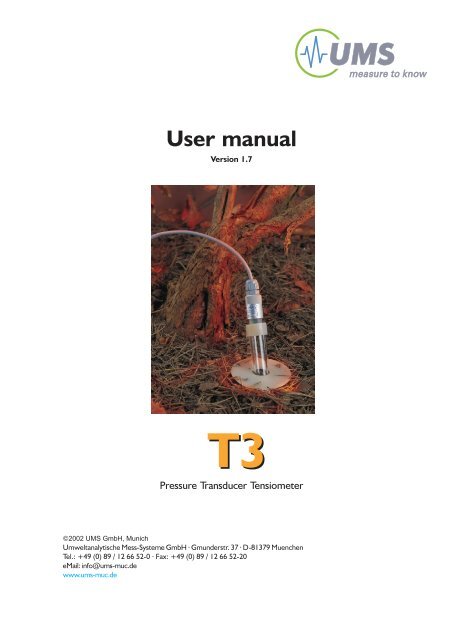
User manual<br />
Version 1.7<br />
<strong>T3</strong><br />
Pressure Transducer Tensiometer<br />
©2002 <strong>UMS</strong> GmbH, Munich<br />
Umweltanalytische Mess-Systeme GmbH · Gmunderstr. 37 · D-81379 Muenchen<br />
Tel.: +49 (0) 89 / 12 66 52-0 · Fax: +49 (0) 89 / 12 66 52-20<br />
eMail: info@ums-muc.de<br />
www.ums-muc.de
Index<br />
1 Sketch of the "<strong>T3</strong>" Tensiometer 3<br />
2 General Description 4<br />
2.1 Tensiometer Construction 5<br />
2.1.1 Sensor Cap 5<br />
2.1.2 Tensiometer Shaft 6<br />
3 General Instructions 7<br />
3.1 How to Connect your Tensiometer<br />
to a Display Unit or a Data-Logging-System 7<br />
3.2 Installation 8<br />
3.3 How to Remove 9<br />
3.4 How to Check the Filling Level, refill on site 10<br />
3.5 Refilling the Tensiometer 10<br />
3.6 Calibration 11<br />
3.6.1 Checking the zero offset 11<br />
3.7 Maintenance and Storage 12<br />
4 Tensiometric Principle and Limits 13<br />
4.1 Theory of Water as Measuring Variable 13<br />
4.2 Theory of Water as Pressure Transmitting Medium 14<br />
4.3 Measuring Range and Standing Time 15<br />
4.3.1 Pressure Transducer 15<br />
4.3.2 Pore Size of the Ceramic Material Used 15<br />
4.3.3 State of the Tensiometer Water 16<br />
4.3.4 Ambient Pressure 18<br />
4.3.5 Ambient Temperature 18<br />
5 Technical Data 19<br />
2
1 Sketch of the <strong>T3</strong> Tensiometer<br />
3
2 General Description<br />
The <strong>UMS</strong> <strong>T3</strong> tensiometer is a probe that can be used in a wide variety of applications.<br />
It is very compatible, safe and extremely simple in handling.<br />
The type of tensiometer is shown on the label (not for newer versions with plug):<br />
<strong>T3</strong>-30<br />
type<br />
length of shaft<br />
[ cm ]<br />
Electronic pressure transducer tensiometers are high resolution measuring devices for<br />
the continuous measurement of water tension in the soil, being used in a wide range of<br />
hydrological studies, soil physical studies or general studies of ecosystems.<br />
The <strong>T3</strong> is used to measure water tension in the soil in the non saturated zone. The water<br />
tension is measured and converted into a defined continuous electrical signal. This signal<br />
can be displayed with a voltmeter and power supply or with the <strong>UMS</strong> Infield 5, which<br />
transmits the electric signal in pressure unit hPa (hecto Pascal). Also, the signal can be<br />
adapted to a data logging unit for logging the water tension signals automatically.<br />
The water tension is a direct measure of the availability of water in the soil for plants and<br />
is therefore an important plant physiological parameter.<br />
In the field of ecosystems, tensiometers are used for hydrological investigations, e. g. for<br />
input and transport studies, gravitational water studies or to measure the water tension<br />
itself as a characteristic value, used in mathematical models of energy - or water balance.<br />
Tensiometers can also be used as control sensors for <strong>UMS</strong>-irrigation systems or as<br />
control sensors for <strong>UMS</strong> suction sampling systems.<br />
Care should be taken in correlating the water tension with the volumetric water content.<br />
This is only possible if the soil texture is known very accurately.<br />
4
2.1 Tensiometer Construction<br />
2.1.1 Sensor Head<br />
The sensor head consists of the pressure transducer, which is connected to a test, supplyand<br />
pressure reference lead, the silicon cone, a protective cap and the type plate. The<br />
sensor principle is based on the “piezoresistive effect” of silicon semiconductors, which<br />
change their specific electric resistance on deformation, and are processed to a defined<br />
signal via a Wheatstone bridge. The deformation is caused by the pressure (or water<br />
tension) on the silicon chip, which is very thin and therefore extremely sensitive to<br />
pressure variations.<br />
The pressure transducer is calibrated for 10.6 Vdc, and so requires a 10.6 Vdc regulated<br />
power supply such as the TV-BATT. The signal changes in direct proportion to the power<br />
supply. At 10.6 Vdc we obtain a signal of 0 hPa ≈ 0 mVdc and 1000 hPa ≈ 103 mVdc.<br />
The tolerance is ± 3 mV, depending on the pressure transducer.<br />
The exact calibration values are shown in the <strong>UMS</strong> Calibration Certificate supplied with<br />
each tensiometer. This is not necessary for tensiometers supplied with Infield-systems.<br />
Since 2001 the signals of all Tensiometers are balanced by potentiometers inside<br />
the pressure senor head!<br />
Since the water tension is measured with respect to the atmospheric air pressure, this<br />
pressure is transferred to the referece port of the pressure transducer inside the body<br />
through the (white) membrane on the cable. This membrane must always have contact<br />
to the atmospheric pressure.<br />
After the tensiometer is filled, the sensor cap is placed on the shaft using the silicon cone.<br />
The protective cap also contains a pull protection for the cable. However, force should<br />
be avoided. (Secure the cable to the tensiometer shaft so that no one can trip over it.)<br />
Although the protective cap reflects the greater part of the sunlight striking it, direct<br />
exposure to the sun should be avoided (Temperature drift). The sensor surface is<br />
electrical isolated to prevent influence of galvanic soil potentials.<br />
5
2.1.2 Tensiometer Shaft<br />
The tensiometer shaft consists of the ceramic cup (also tensiometer cup), the acryl glass<br />
shaft and the excess pressure protector.<br />
The tenisometer ceramic acts like a porous filter. Firstly, it is water-permeable, so that<br />
the water tension of the soil can be transmitted to the tensiometer water and, via this,<br />
to the pressure transducer. Secondly, when wet it is impermeable to air below a certain<br />
pressure, so that a “water tension” (under-pressure) can build up in the tensiometer<br />
shaft. Every ceramic is selected by <strong>UMS</strong> for a defined pore size and homogeneous pore<br />
structure.<br />
The tensiometer water must be degased and deionized, so it will transmit differing<br />
pressures hydraulically to the pressure transducer largely without changed volume.<br />
Gases which are dissolved at atmospheric presseure will become gasiform with rising<br />
water tension.<br />
If the soil dries out, the tensiometer water vaporises at a pressure of about 900 hPa,<br />
expands, and "runs" out of the cap. If the soil dries out further, the water film in the pores<br />
of the ceramic disintegrates, allowing air to enter. When this happens, a refill of the<br />
tensiometer is necessary.<br />
At the upper end of the shaft, two diametrically opposed holes are drilled. A silicone<br />
rubber ring is stretched over them. This allows excess pressure built up through too rapid<br />
placement of the sensor cap on the shaft to be released through these holes (excess<br />
water can escape). The pressure sensor is thus protected from excess pressure.<br />
6
3 General Instructions<br />
3.1 How to Connect Your Tensiometer<br />
to a Display Unit or a Data-Logging-System<br />
The pressure transducer works as an asymmetric Wheatstone full bridge.<br />
Tensiometers with plug (new version since 2001) that have a black cable and the<br />
4-pin plug M12/IP67 have the following configuration:<br />
Tensiometers without plug and the grey cable have this configuration:<br />
- brown wire is power supply minus, white wire is power supply plus<br />
- yellow wire is signal minus, green wire is signal plus<br />
Note: Do not connect the signal minus to the power supply minus input of your measuring unit!<br />
The signal minus is not '0V' or 'Ground' when the Tensiometer is supplied with -5V/+5.6V,<br />
because then the signal range is between +3.2 V and 6.8 V with reference to power supply.<br />
As the pressure transducer is a Wheatstone full bridge, it has to be connected in a certain<br />
mode. Please read therefore the manual of your display unit or data-logging-system<br />
before connection.<br />
7
3.2 Installation<br />
Please note that the water column inside the shaft causes an hydrostatic pressure on<br />
the pressure sensor and has to be compensated. The water column is the shaft length<br />
plus 3 cm for the cup! Withdraw 1 hPa for each cm of water column from the reading:<br />
Correct soil water tension [hPa] = measured reading [hPa] - water column [cm]<br />
Find the correction value depending on the resp. shaft lenght on the calibration certificate!<br />
Example for 30 cm shaft, reading 130 hPa: Correct tension = 130 hPa - 33 cm = 97 hPa<br />
The tensiometer has an outer diameter of 20 mm. An appropriately large drilling rod<br />
(<strong>UMS</strong> accessory) must be selected.<br />
- drill a hole of the required depth at the drilling location.<br />
- In stony soil, it may be necessary to drill the hole several times. Should the walls of<br />
the hole fail to hold, <strong>UMS</strong> lining tubes can be used.<br />
- Pour a thin paste of quartz clay powder and water into the hole. For loamy soil, use<br />
ca. 20 ml plus ca. 100 ml of water; for coarse, clay-like soil ca. 30 ml; for sandy soil<br />
ca. 100 ml and for stony soil adjust the proportions according to the stone content.<br />
- Now remove the plastic container from the tensiometer cup, turning the container<br />
slowly (clockwise when viewed from below).<br />
Immediately insert the tensiometer in the hole in the soil.<br />
8<br />
Filling the <strong>T3</strong>
3.3 How to Remove<br />
If the tensiometer is to be removed from the soil, you will need the following equipment:<br />
1. The plastic bottle (protective container for the ceramic cap) with ca. 10 ml of<br />
deionised water.<br />
2. A five liter container of water (tap water).<br />
3. Adhesive tape and a water-proof marker.<br />
4. For each tensiometer, a rod approximately 20 mm in diameter and of a length<br />
sufficient to allow the tensiometer to be reinserted at the same location later. The rod<br />
should be rounded at the end. (The shape of the tensiometer cup is ideal.)<br />
Procedure:<br />
Hold the tensiometer by its shaft and pull it vertically out of the soil, avoiding sideways<br />
movements. After removal, place the plastic bottle, half-filled with water, over the ceramic<br />
cup, rotating it slightly clockwise. Push the rod into the hole in the soil with a slight turning<br />
motion. Mark the rod with the tensiometer number. If the tensiometer is connected to a<br />
logger, the signal channel should also be noted on the end of the cable.<br />
Please note!<br />
The tensiometer should not be rotated when inserted and removed. If it is<br />
removed after a dry period and the tensiometer is stuck, water poured along the shaft<br />
works wonders. Should the tensiometer remain immovable, pull it out by turning screw<br />
up, using as little force as possible.<br />
9
3.4 How to Check the Filling Level, refill on site<br />
In order to accertain that the tensiometer is still properly filled, check that there is an air<br />
bubble in the shaft directly beneath the sensor cap. This bubble should always be as<br />
small as possible, or better not be present. If it is longer than 2 cm, pull off the sensor<br />
cap and refill the shaft to the top with deionized water. Then replace the sensor cap.<br />
3.5 Refilling the Tensiometer<br />
Place the tensiometer in a vessel with deionized water. The ceramic cap must be<br />
immersed to a depth of at least 20 cm. The shaft itself is not filled with water, since this<br />
would lead to air being trapped within the walls of the ceramic cap. Wait about 30 minutes<br />
until the water meniscus can be seen in the tensiometer shaft above the ceramic cap.<br />
Now empty the shaft and fill the tensiometer shaft to the top with deionized water.<br />
Place the sensor cap on the shaft with a slight rotational motion and connect the<br />
tensiometer to your display device. Wrap a damp cloth around the sensor cap (simulating<br />
dry soil). A water tension of 850 hPa should be attainable (minus the shaft length - e.g.<br />
for a shaft of 30 cm => 850 - 30 = 820 hPa). The shaft must be held vertically with the<br />
sensor cap pointing downwards.<br />
In case bubbles appear inside the shaft wall, these can be caused to rise by gently<br />
tapping sideways. Then remove the sensor cap again in order to refill the shaft to the top.<br />
If the sensor cap is now replaced, the water tension should increase rapidly if a dry cloth<br />
is wrapped around the ceramic cap. Wrap the ceramic cap in a damp cloth or place it<br />
in a water-filled vessel so that at least the ceramic cap is covered with water.<br />
Your <strong>T3</strong> is now ready for use.<br />
10
3.6 Calibration<br />
The most important thing is to check the zero offset, since this value drifts very much<br />
faster than the gain. The stability (of the zero point) over one year is typically 0.5% of full<br />
scale. To maintain an accuracy of 5 hPa, calibration has to be done annually.<br />
To recalibrate the slope you need the <strong>UMS</strong> Calibration Kit.<br />
3.6.1 Checking the zero offset<br />
For checking the zero offset, it is not necessary to use the <strong>UMS</strong> Calibration Kit. This<br />
check can be done much more easily:<br />
shaft<br />
Place the tensiometer in a beaker<br />
until the ceramic end is 10 mm below water level.<br />
ceramic cup<br />
The tensiometer must have previously been filled in the correct way.<br />
10 mm<br />
After about 5 minutes or less (time depends on the filling level) you should get a constant<br />
value on your display unit or data-logging-system. This value should not vary more than<br />
± 5 hPa from the 0 hPa-value in the calibration certificate.<br />
If it exceeds this, the new value should be written into your calibration certificate with the<br />
calibration date. How to change the zero offset of your display/recording unit should be<br />
shown in the corresponding user manual of your display unit or data logger.<br />
If the slope is also to be calibrated, <strong>UMS</strong> offers this as a service.<br />
11
3.7 Maintenance and Storage<br />
3.7.1 Cleaning the Tensiometer<br />
Clean the tensiometer with a damp cloth (water) or with petroleum ether: Do not use acid<br />
or solvent, as they could attack the adhesive joint or the material itself.<br />
3.7.2 Storage<br />
Place the tensiometer as near to the vertical as possible in a pail of water so that the<br />
ceramic cap cannot dry out. To prevent the formation of algae, the tensiometer should<br />
be stored in a dark place. In case of storage for longer than 3 months, the <strong>T3</strong> can also<br />
be stored dry. Filled tensiometers always must be protected from freezing!<br />
12
4 Tensiometric Principle and Limits<br />
4.1 Theory of Water as Measuring Variable<br />
Water tension measurement (absorptive tension measurement) as a direct means for the<br />
measurement of water available in soils for plants involves the measurement of total<br />
potential of water retention in the soil under investigation (excluding osmotic potential,<br />
potentials of differential pressure and gravitation).<br />
The saturation state of soil (level of ground water, resp.) determines the extent of water<br />
absorption with regard to the water tension in soil through the ceramic material by the<br />
tensiometer which is otherwise hermetically sealed. The porous properties of the ceramic<br />
material (sintered Al 2<br />
O 3<br />
) are considered ideal.<br />
The atmospheric underpressure built up in the tensiometer (assuming the above mentioned<br />
potentials are neglected) minus the pressure accounted for by the vertical length<br />
of the tensiometer is equivalent to the water tension in the soil under investigation. (The<br />
water column in the tensiometer leads to a hydrostatic potential p acting upon the<br />
pressure receptor due to its "hanging weight", and should be added to the measured<br />
value according to the equation as follows:<br />
p = density x g x h (1 Pa (Pascal)= 1 N/m 2 )<br />
This potential, however, has been compensated by calibration.<br />
Example:<br />
Vertical difference between pressure receptor (h 1<br />
) and ceramic tip (h 2<br />
) = 10 cm,<br />
p<br />
= 1000 kg/m 3 x 9.81 m/s 2 x 0.1 m<br />
= 981 kg/ms 2 (1 N = kg·m/s 2 )<br />
= 981 N/m 2 (1 hPa (Hektopascal) = 100 N/m 2 )<br />
p<br />
= 9.81 hPa<br />
13
The following schematic view informs of the measuring principle and the hydrostatic<br />
relations:<br />
water tension<br />
cmWS pF<br />
5<br />
10 7<br />
5<br />
10 5<br />
4,2<br />
10 4,2<br />
3<br />
10 3<br />
300 2,5<br />
60 1,8<br />
sand<br />
coarse<br />
clay<br />
clay<br />
PWP<br />
FK<br />
water<br />
not available<br />
for plants<br />
water<br />
available<br />
for plants<br />
∆ h<br />
∆ h<br />
∆ p<br />
10<br />
1<br />
1<br />
0<br />
20 40 60<br />
water content [Vol%]<br />
water level<br />
figure 1: Measuring Principles and Hydrostatic Relations<br />
(taken from: Lehrbuch der Bodenkunde, Scheffer/Schachtschabel 1981)<br />
4.2 Theory of Water as Pressure Transmitting Medium<br />
Since deionised and degassed water with a modulus of compression of approx. 1 can<br />
be regarded as an ideal non-compressible liquid, it is useful as a pressure transmitting<br />
medium in the range of atmospheric pressure p 0<br />
(= 0 hPa) to atmospheric underpressure<br />
p 1<br />
(= 950 hPa) in a temperature range of > 0 °C to < 30 °C without change of volume<br />
(see curve of the water vapour pressure relationship).<br />
This means that the tensiometer with its mechanical tightness in the said pressure range<br />
exchanges a very limited amount of water via the ceramic material during the process<br />
occuring when pressure is transfered from the ceramic tip to the pressure transducer<br />
(sensor). This applies to the use of relatively rigid material like acrylic glass and the<br />
pressure receptor.<br />
14
The tensiometer has been designed so that only a small amount of water is exchanged<br />
when the soil cycles from wet to dry (0 to 850 hPa).<br />
This ensures that the tensiometer can last for many drying cycles, provided that the water<br />
inside is free from dissolved gasses and all bubbles (including microscopic ones).<br />
4.3 Measuring Range and Standing Time<br />
The extent of measuring depends on the following parameters:<br />
1. Pressure receptor<br />
2. Pore size of ceramic cup<br />
3. State of tensiometer water<br />
4. Ambient pressure<br />
5. Ambient temperature<br />
4.3.1 Pressure Transducer<br />
The pressure transducer can tolerate pressures in the range of + 3000 hPa to - 3000 hPa<br />
(theoretical value) non-destructively and measure them linearly in the range of +1000<br />
hPa to -1000 hPa (linearity error < 0.1%).<br />
4.3.2 Pore Size of the Ceramic Material Used<br />
In order to measure soil water tension, a porous ceramic cup is incorporated for the<br />
transmission of water. The ceramic, when wet, is impermeable to gases. This is the<br />
essential requirement for the build-up of a underpressure in relation to the ambient<br />
pressure in the tensiometer.<br />
15
The bubble point - i.e. the first entrance of air into the ceramic material - which also leads<br />
to a limitation of the measuring range, may be calculated according to the formula of<br />
capillary tension as follows:<br />
K =<br />
40 · σ<br />
D<br />
D = Pore diameter [µm, 10 -6 m]<br />
σ = Surface tension [dynes/cm]<br />
(water: 0°C:75.6; 20°C:72.7; 50°C:67.8)<br />
K =<br />
Capillary tension [hPa]<br />
Air may burst in if pressure difference of ceramic inside to ceramic outside exceeds<br />
capillary tension. Then the water film in the biggest pores (the biggest pore channel) will<br />
disintegrate.<br />
Since the bubble point depends on the largest pore line from outside to inside, the latter<br />
should be as homogeneous as possible. To avoid the flow resistance becoming too high,<br />
the pore diameter must not be too small. The ceramic material used has a pore size of<br />
1 µm together with high homogeneity of pore size distribution. It can block up pressures<br />
of theoretically 3000 hPa (only for water-satuated ceramics) and therefore provides for<br />
best performance in tensiometers. Because of its fine pores the shaft may become<br />
covered by microorganisms in time. Rinse it in dry cleaning spirits carefully and at length.<br />
4.3.3 State of Tensiometer Water<br />
The tensiometer water limits the measuring range, as can be seen from the two-phase<br />
diagram for water and water vapour.<br />
When the tensiometer contains dissolved gases, the vapour point is raised, which<br />
restricts the measuring range considerably. Therefore care should be taken to degas the<br />
deionised water as completely as possible (e.g. by boiling).<br />
16
If there are no gases dissolved in the water, the measuring range may be repeatedly<br />
traversed. (The diffusion of gases dissolved in water through the ceramic material may<br />
then be neglected.)<br />
However, if the tensiometer water contains dissolved gases which get gaseous before<br />
reaching the soil water tension, water will flow through the ceramic material outside.<br />
Dissolved gases pass once more into the tensiometer, when soil water tension gets<br />
nearer to zero. In view of the resulting exponential conditions the tensiometer water has<br />
therefore to be well degassed to obtain a long lifetime (= time that is needed until refill<br />
is necessary).<br />
If the water tension values are low, the tensiometer water may be regenerated less often.<br />
This also applies for water tension values which show only small changes.<br />
pressure p [hPa]<br />
1000<br />
900<br />
800<br />
700<br />
600<br />
500<br />
400<br />
liquid phase<br />
300<br />
200<br />
100<br />
vacuum<br />
vapour phase<br />
31,2<br />
0<br />
0 10 20 30 40 50 60 70 80 90 100<br />
temperature t [˚C]<br />
figure 2: Two-Phase Diagram of Water/Water Vapour<br />
17
4.3.4 Ambient Pressure<br />
The maximum measuring value depends directly on the ambient pressure.<br />
4.3.5 Ambient Temperature<br />
The maximum measuring value depends on the vapour point of water which itself is<br />
temperature dependent, and therefore also depends on the ambient temperature (see<br />
vapour point curve exemplified).<br />
We wish you the best success in measuring.<br />
Do not hesitate to contact us for further questions.<br />
18
5 Technical Data<br />
Dimensions<br />
Cable length<br />
Measuring principle<br />
Length of ceramic cap: ca. 50 mm<br />
Diameter of ceramic cap: ca. 20 mm<br />
Length of tensiometer shaft: as desired, max. 200 cm,<br />
material acrylglas<br />
Height of the sensor cap: ca. 40 mm<br />
Diameter of the sensor cap below: ca. 14 mm<br />
5 m standard, as desired<br />
Measuring the soil water tension, transmitted<br />
via ceramic cup onto the tensiometer water<br />
and pressure transducer giving an analog signal<br />
Range 0 - 850 hPa = pF 2.9<br />
minus shaft length (1cm ≈ 1 hPa)<br />
Signal<br />
Impedance<br />
Temperature shift<br />
Hysteresis<br />
Stability over<br />
one year<br />
Sensor<br />
Electronic principal<br />
Common mode range<br />
Power supply<br />
Current consumption<br />
0 - 100 mVdc ± 3 mV, calibrated<br />
exact values are recorded for each tensiometer<br />
≈ 2.6 kΩ<br />
compensated,<br />
typ. drift: 0.5% FS above 25 °C<br />
typ. 0.1% FS<br />
typ. 0.5% FS<br />
piezoresistive pressure transducer,<br />
overpressure max. ± 3000 hPa<br />
assym. wheatstone full bridge<br />
signal distance to mass with 10,6 Vdc supply: 2.8 - 6.8 Vdc<br />
10.6 Vdc (5-15 Vdc), stabilisized<br />
≈ 1.3 mA (with 10.6 Vdc)<br />
Umweltanalytische<br />
Mess-Systeme GmbH<br />
All rights reserved<br />
© 2001 <strong>UMS</strong> GmbH, München.<br />
Gmunderstraße 37<br />
D-81379 München<br />
Tel.: ++49 (0)89 / 12 66 52 - 0<br />
Fax: ++49 (0)89 / 12 66 52 - 20<br />
eMail: info@ums-muc.de<br />
www.ums-muc.de<br />
19